A Multicore Architecture Focused on
Accelerating Computer Vision Computations
Liberios Vokorokos *, Eva Chovancová *, Ján Radušovský*, Martin Chovanec**
* Department of Computers and Informatics, Faculty of Electrical Engineering and Informatics, Technical University of Košice
Letná 9, 04001 Košice, Slovak Republic
eva.chovancova@tuke.sk, liberios.vokorokos@tuke.sk, jan.radusovsky@tuke.sk
** Institute of Computer technology, Technical University of Košice, Letná 9, 04001 Košice, Slovak Republic; e-mail: martin.chovanec@tuke.sk
Abstract: This paper deals with accelerating computer vision computations using a specialized multicore architecture. Computer vision is one of the fastest-evolving segments of computer science. Even though computer vision uses time-consuming methods, the processing can be accelerated using specialized multicore processor architectures. Single- core processors are a legacy, since they have reached their physical limits. The way to go is to use multicore architectures, which can be also used to accelerate computations in specialized areas such as computer vision. This paper describes a specialized multicore architecture that can be used to accelerate time-consuming calculations in the field of computer vision. The architecture proposed in this paper belongs to the Harvard architecture family.
Keywords: image; architecture; Harvard concept; Princeton concept; threshold; control unit; processing unit
1 Introduction
Computing and information systems have become an integral part of everyday life and also of research. In research, there is a demand for systems that provide more power, due to the time-consuming calculations involved.
The computing power of single-core processors – which are mostly examples of the Von Neumann architecture – may be increased by increasing the capacity of the individual components of the computer; this goes hand in hand with increasing the amount of available memory in the system. However, this method of gaining more computing power brings with it an increase in the costs of the development
of the individual components. It also reveals certain physical limits. The method of increasing the capacity of the individual components to obtain higher performance has been superseded; new developments tend to target multicore processors. Having multiple processors on a single chip brings the advantage of sheer processing power; nothing is free though. With multicore architectures, one may see different problems, such as power consumption and heat dissipation. The architecture must be designed so that the heat is distributed and there are no hot links. Distributed and shared on-chip caches must adhere to the rules of coherence to ensure data accuracy.
The present work analyses the various multicore architectures, based on which is designed a specialized multicore architecture for accelerating calculations in computer vision. The present work was supported by the Slovak Research and Development Agency under contract no. APVV-0008-10. This research is the result of the implementation of the “Research Centre for efficient integration of the renewable energy sources” project, ITMS: 26220220064, supported by the Research & Development Operational Programme funded by the ERDF.
2 Architecture Concept
When designing a specialized architecture, the concept choice is important. The basi concepts we have taken into account when designing our architecture were the following:
• the Harvard concept; and
• the Princeton concept.
Figure 1
a) the Harvard architecture, b) the Princeton architecture
The Harvard concept (Figure 1a) is a computer architecture with a physically separated storage space and signal path for instructions and data. This means that it has a separate address space for both programs and data. Today, most processors have implemented a separate signal path due to performance reasons. [2] [6] [12]
a) CPU
CPU
Data memory
Instruction memory
Data & instruction memory b)
In conjunction with a modified Harvard architecture, it is possible to support tasks such as reading the program implementation directly from the disk as data and then executing them. In the Harvard architecture, it is not necessary to share the memory properties, because the timing, the technology implementation and the structure of addressable memory may vary. In some systems, the instruction memory is larger than the memory for data, because the address of the instruction is wider than the address of data. One of the most notable examples of the Princeton concept is the Von Neumann architecture, which is simpler than the newer Harvard architecture. The Von Neumann architecture – in comparison with the Harvard concept – has only one memory (Figure 1b), which is used to store both data and instructions; this means that it contains a common set of data and instruction addresses. [12] [13]
Consequently, it is necessary to ensure that the processor does not interpret data as instructions, and vice versa. The CPU accesses the memory in the same way, both in the case of instructions or data. It uses the same addresses, data and control signals. This memory structure allows for the existence of self-modifying programs.
The Von Neumann architecture is a system that can store the program into the operating memory, and thus the instructions and data are stored in a RAM memory. This RAM memory enables both reading and writing operations. In the Von Neumann architecture, the CPU can read instructions or read/write data from/to the memory. These operations cannot be performed simultaneously because both the data and the instructions use the same memory. However, the Harvard architecture can load instructions and data at the same time because both are stored at their own memory. Therefore, the Harvard architecture is faster. [2]
[6]
3 Multicore Processors
High-performance processor architectures are mostly represented by multiple processor cores on a single chip. These architectures have the potential to provide a higher maximum throughput; they scale better and provide higher performance than monolithic architectures. The current trend in technology development aims at new types of processors which should meet the need for higher performance without increasing power consumption and heat. [1] [3] [4]
Multi-core processor architectures allow us to achieve increased performance and to reduce heat by the integration of two or more processor cores in a single processor case. Today, processors sporting a large number of cores are being produced. These processors have the most logical structure – a two-dimensional grid; they apply control flow and data flow core architectures. Considering the definition of the processor, we can describe the multi-core processor as an
integrated circuit to which two or more processors (cores) connect. Such a design enables improved performance, reduced energy consumption and more efficient, simultaneous task processing. All of this has resulted in a development boom in the field of multi-core processors because single-core processors have reached their limits in terms of performance and speed. [1] [3] [4]
4 The Proposed Architecture
The proposed processor architecture is based on the analysis of multi-core processors and computer vision. Due to the advances in the development of multi- core processors and computer vision, i.e. the use of parallel algorithms, it is advisable to use multi-core processors to accelerate computations in this field. The use of specialized multi-core processors results in higher performance and faster data processing due to the fact that the image is distributed to the individual cores.
It takes less time to process the same amount of data. [5] [7] [19]
4.1 Image Mapping
The proposed specialized processor allows for the use of several approaches when mapping the image; these differ in the distribution of the digital image, but also in the number of required cores. Figure 2 represents the way the digital image is mapped to the individual processor cores. This approach may be applied if the size of the digital image is 256×256 pixels, which is also the maximum size of the processed image. This size is given by the maximum capacity of data memory, which is large enough for testing purposes; nevertheless, it may be expanded in the future. With this approach, we divide the image into equally large parts that exactly correspond to the memory size of a single core. [5] [7]
Figure 2
Image mapping (256×256 pixels)
If the image is smaller than 256×256 pixels, there are two ways to split the mapped image. The first – even – method uses all the processor cores, so all cores are equally busy, but they do not use their entire memory. The second method to use with a smaller picture is the uneven method. This method uses the entire memory capacity, but it is not as effective as the previous one, because it requires more time to process the same image than the even method.
Due to the memory capacity used for testing, the maximum input image size is 256×256 pixels, and since we have available 16 cores with a memory capacity of 256 points × 256 points × 3 bytes (RGB) × 4 banks = 786432 bytes. The image is stored in separate memory banks; therefore, we can load 4 different images simultaneously and process them sequentially. [5] [7]
4.2 Instruction Set
To execute various operations over the input images, we need a set of instructions representing the operations in question. Each of these instructions has a defined format (Figure 3), as follows:
Figure 3 Instruction format
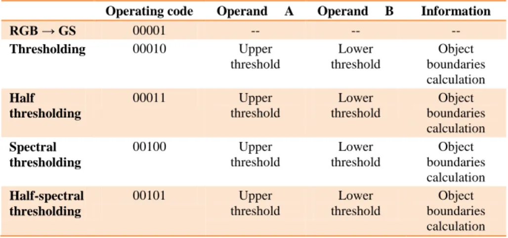
The instruction set shown in the following table contains a list of instructions and their parameters necessary for the execution of the instructions over the input data:
Table 1 Instruction set
Operating code Operand A Operand B Information
RGB → GS 00001 -- -- --
Thresholding 00010 Upper
threshold
Lower threshold
Object boundaries calculation Half
thresholding
00011 Upper
threshold
Lower threshold
Object boundaries calculation Spectral
thresholding
00100 Upper
threshold
Lower threshold
Object boundaries calculation Half-spectral
thresholding
00101 Upper
threshold
Lower threshold
Object boundaries calculation Operating
code 4 bits
Source bank 2 bits
Target bank 2 bits
Operand A
2 bits
Operand B
2 bits
Writing to register
00111 Upper
threshold
Lower threshold
Object boundaries calculation As is evident from Table 1, for the calculation of the various thresholding types, one has to specify operands A and B, i.e. the upper and lower threshold. We can define the object boundaries in a digital image using these thresholds and thus tell these from the background.
5 The Covitor Processor
The proposed processor – Covitor – is a processor with 16 cores specialized in digital image processing and using the instruction set described in the previous section. This processor is an instance of the Harvard architecture; it has its own data memory and its own instruction memory. Having two memories makes access to data and instructions faster. The cores of the Covitor processor are arranged as a 4×4 grid. The structural diagram of the Covitor processor appears in Figure 4.
Figure 4
The structural diagram of the 16-core processor
The processor operates in two modes; the Pmod and Cmod instructions are used to set the system into programming or computing mode. In programming mode, the input values are read into the registers / into the memory and the system timing is set. Then the system switches to computing mode, which will run calculations based on the program – these are the instructions applied to the data.
The done signal marks the end of the data processing cycle, while the data are located at specific address in memory. If done is set to one, the cycle is terminated. The address is set to the subsequent address in the memory, and the next cycle of calculations starts. The Covitor processor contains two components listed below; their connections are defined by mapping:
• Cores;
• Decoders.
Ab (1:0) Ac (3:0) Adr (11:0) Data (23:0) Clr Clk Rst Cmod Pmod Sigwrpp Sigr Sigw Tag
A Core is a universal processor core, mapped to 16 cores; the Decoder components are used to address the cores.
6 Processor Cores
The Covitor processor was designed as a multi-core processor with 16 cores. The architecture is a member of the Harvard architecture family; it has a separate memory for both instructions and data.
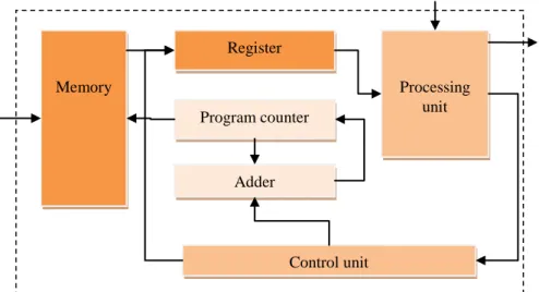
The instruction memory is located directly in the core. The data memory is larger than the instruction memory and it sits in the processing unit. The scheme of a core is presented in Figure 5.
Figure 5 A processor core
By having 16 cores in a processor we achieve higher performance, which we need for faster image processing. This is expressed by the following formulae:
d
n t m n d
t m
2 16
1 (1)
In these equations, m refers to the amount of pixels of a digital image, while n refers to the number of cores used. It is also necessary to calculate with the time needed for loading and distributing the data to each of the cores, which is expressed by the value of d. Each core of the Covitor processor consists of a memory, a register, a program counter, an adder, a control unit and a processing unit.
Memory Processing
unit Register
Program counter
Adder
Control unit
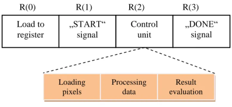
The processing unit includes an arithmetic logic unit. The digitized input image is loaded into the memory, located in a processing unit, and the instructions are loaded into the memory located in the core. The image processing is divided into four phases, controlled by the control unit. In the first phase, the instruction is loaded into the register. Then, in the second phase, a start signal is sent to the processing unit. In the third phase, the image processing starts, based on the particular instruction. The last, fourth phase is the stop signal itself, which terminates the processing cycle.
6.1 The Control Unit
The control unit is a finite state machine with four states describing image processing. The transitions between the states are performed by the control logic.
In this logic, the signals from the control unit and the required conditions to make transitions are taken into account. The control unit controls the process by means of the R(0), R(1), R(2) and R(3) signals, which initialize the transitions between the various states of the finite state automaton. Figure 6 represents process control implemented using the above signals.
Figure 6 Process control
For the program to function properly, we have to switch to computing mode. If the program is in boot mode, the control unit will not start and image processing will not take place.
6.2 The Processing Unit
The processing unit is a part of the processor core; its main task is to implement the instructions processing the input data loaded in its internal memory. It also contains a partial logic circuit, controlling the termination of image processing.
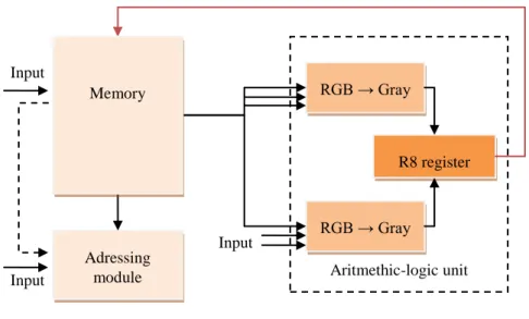
The implementation of the processing unit is based on the logic circuit presented in Figure 7.
R(0) R(1) R(2) R(3) Load to
register
„START“
signal
Control unit
„DONE“
signal
Loading pixels
Processing data
Result evaluation
Figure 7 The processing unit
The processing unit is responsible for processing the image by thresholding or converting it from RGB to grayscale. The processing is started by a starting signal; this indicates the start of the process itself. The processing output is stored in the R8 output register, both after thresholding and also after conversion to greyscale.
We have created a set of rules to determine when and which results may be entered in the R8 register to ensure the accuracy of the data stored in the register.
An important part of the processing unit is the addressing module; it determines the appropriate memory address, which is used to read further data for processing – as described lower in the text. A further important part of the processing unit is the arithmetic-logic unit, with two logic sub-circuits. One of these converts the digital image on the input from RGB format to grayscale. This RGB- grayscale conversion is based on the following equation:
B G
R
grayscale0,3* 0,59* 0,11* (2) The second logic circuit is responsible for processing the image by means of various types of image thresholding operations. In our proposal, we use four thresholding types:
• Simple thresholding;
• Half-thresholding;
• Spectral thresholding;
• Half-spectral thresholding.
Input Input
Input Adressing
module Aritmethic-logic unit
RGB → Gray
RGB → Gray
R8 register Memory
During thresholding, the input data of the digital image are compared with the upper and lower threshold values stored in the respective registers. Next, we perform a comparison to decide whether the given image point belongs to the subject or the background.
Figure 8 The addressing module
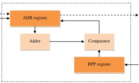
As mentioned above, the addressing module (Figure 8) is a significant part of the processing unit. The operation of this module is two-fold: its first task is to terminate the image processing when reaching the last address of the stored pixel data, while the second is to set the pixel addresses.
The ADR register stores a value that refers to the address from which data are taken for processing. If the input controlling R signal arrives, the adder increments the value stored in the ADR register. The incremented value is compared by the comparator with the value stored in the RPP register. If it is smaller or equal, the data processing continues with the next address in the sequence and the cycle repeats again.
7 Simulation
One way of speeding up image processing is to use multiple cores on a single chip; the load is spread over multiple cores, and thus each core has to process a smaller number of pixels.
In the simulation we have used different numbers of cores for image processing.
We have seen that an increased number of cores allows us to process more pixels in the same period (Figure 9).
ADR register
RPP register
Adder Comparator
0 125 250 375 500 625 750 875 1000
0 500 1000 1500 2000 2500 3000 3500 4000
Number of pixels
Time t [SC]
1 core 4 cores 16 cores
Figure 9
Image processing performed on multiple cores
As is evident from the graph, when processing the same image with 16 cores of a single chip, we need 16-times fewer machine cycles (SC) than we would need using a single core. In this simulation we used a 256×256 pixel image, so the total number of pixels processed was:
pixels 256 * 256 65536
(3) The time required for processing the image using a single core is given by the following equation:t256*256*4 (3)
t262144SC (4)
When processing the image using the Covitor processor, the total load spreads to 16 cores, which reduces the processing time. In the simulation, we have spread the load evenly due to a memory limitation (Figure 10 – the maximum amount of memory that can be processed by each core is evident from this figure).
We have imposed the image size limitation due to testing difficulties, though in the future it will be possible to expand the memory of the proposed processor to store and retrieve information about the image, i.e. process higher resolution images.
0 1000 2000 3000 4000 5000
1 2 3 4 5 6 7 8 9 10 11 12 13 14 15 16 Pixels
Number of cores
Figure 10 Even load distribution
Uneven load distribution may be used, too, on the condition that the processed image has a smaller resolution (64×64 pixels) than the maximum memory capacity (Figure 11).
0 100 200 300 400 500 600
1 2 3 4 5 6 7 8 9 10 11 12
13 14 15 16 Pixels
Number of cores Figure 11
Load distribution with 64 × 64 pixel image resolution
When processing smaller resolution images, the load can be spread evenly or unevenly, as presented in the graph (Figure 11). In even load distribution, all cores are used, but only a part of their memory capacity. When applying uneven load distribution we use the whole memory capacity, but only some cores. In terms of efficiency, it is preferable to use even load distribution, because less time is needed to process the image than with the uneven load distribution.
The simulations we have implemented have demonstrated the correct functionality of the proposed architecture and the efficiency of image processing, too. We have also witnessed the acceleration of image processing computations.
Using multiple cores for image processing allows faster computation in linear proportion to the number of cores. This acceleration may be even 16-fold when using even load distribution.
When simulating image processing using the Covitor processor, we have witnessed that the acceleration depends on the load distribution type. Even load distribution is more efficient than uneven load distribution.
Conclusion
In our work we have designed and implemented a specialized multicore architecture focused on accelerating computer vision computations. The design of this architecture was based on the analysis of multicore processors, which has shown that the Harvard architecture is faster when accessing data and instructions stored in memory.
The speedup of the proposed architecture depends on the type of load distribution used; even load distribution is more effective than uneven distribution. The proposed data (image) memory has its limitations, though this can be overcome in future. This limitation is present due to testing reasons.
Moreover, the instruction set consists only of basic instructions that correspond to the various thresholding types and to RGB-grayscale transformation. This instruction set can be extended by instructions corresponding to image extraction by connected components (4- and 8-neighbours). These methods use the neighbour’s pixels to perform computations, so the data might overlap. Therefore it is necessary to solve cache memory coherence problems. This specialized architecture may also process interactive algorithms.
Acknowledgements
The present work was supported by the Slovak Research and Development Agency under contract no. APVV-0008-10. The present research is the result of the implementation of the “Research Centre for efficient integration of the renewable energy sources” project, ITMS: 26220220064, supported by the Research & Development Operational Programme funded by the ERDF.
References
[1] G. Blake, R. Dreslinski, T. Mudge: „A Survey of Multicore Processors“, Signal Processing Magazine, IEEE, pp. 26-37, 2009, 1053-5888/09
[2] M. Jelšina: „Architektonické riešenie počítačového systému data flow KPI“
[Data-flow computer system architecture] Košice, Slovakia: Elfa, 2004, ISBN 80-89066-86-0
[3] B. De Ruijsscher, G. Gaydadjiev, J. Lichtenauer, E. Hendriks: „FPGA Accelerator for Real-Time Skin Segmentation“ 2006, ISBN 0-7803-9783-5 [4] P. Gepner, M. Kowalik: „Multi-Core Processors: New Way to Achieve
High System Performance“, Proceedings of the International Symposium on Parallel Computing in Electrical Engineering PARELEC'06, Computer Society, 2006, ISBN: 0-7695-2554-7
[5] B. Chanda, D. Majumder: „Digital Image Processing and Analysis“, PHI Learning Pvt, 384 pages, 2004, ISBN 8120316185
[6] L. Vokorokos, N. Ádám, J. Trelová: „Sequential Threads In Data Flow Computers“, AEI '2010 : International Conference on Applied Electrical Engineering and Informatics, Venezia, Italy, September 5-13, Košice, Slovak Republic, 2010, pp. 54-58, ISBN 978-80-553-0519-6
[7] S. Klupsch, M. Ernst, S. Huss, M. Rumpf, R. Strzodka: „Real Time Image Processing Based on Reconfigurable Hardware Acceleration“, www.mpi- inf.mpg.de/~strzodka/papers/public/KlErHu_0 2fpga.pdf
[8] R. Kumar, V. Zyuban, D. Tullsen: „Interconnections in Multi-Core Architectures“, Proceedings of the 32nd International Symposium on Computer Architecture (ISCA’05), 2005, ISBN 1063-6897/05
[9] J. Nurmi: „Processor Design: System-On-Chip Computing for ASICs and FPGAs“, Springer, 2007, ISBN 978-1-4020-5530-0
[10] C. Rafael R. Woods: „Digital Image Processing“, Prentice Hall, 2008, ISBN, http://lit.fe.uni-lj.si/showpdf.php?lang=slo&type=doc&doc=dip
&format=0, 0-13-168728-x
[11] V. Hlaváč: „Počítačové Vidění“ [Computer vision], Prague: Grada a.s., 252 pages, 1992, ISBN 8085424673
[12] L. Vokorokos: „Princípy architektúr počítačov riadených tokom údajov“
[Principles of data-flow computer architectures], Košice: Copycenter, spol.
s r.o., 2002, p. 147. ISBN 80-7099-824-5
[13] L. Vokorokos, B. Madoš, A., Baláž, N. Ádam: „Architecture of Multi-Core Computer with Data-driven Computation Model“, Acta Electrotechnica et Informatica, pp. 20-23, 2010, ISSN 1335-8243
[14] R. Young: „How Computers Work“,Que Publishing, 2009, 464 pages, ISBN-10: 0789736136
[15] A. C. Bovik: „The Essential Guide to Image Processing“, Academic Press, 880 p, 2009, ISBN: 9780123744579
[16] J. Dennis, G. Gao: „An Efficient Pipelined Dataflow Processor Architecture“, Supercomputing '88 Proceedings of the 1988 ACM/IEEE conference on Supercomputing, s. 368-373, IEEE Computer Society Press Los Alamitos, ISBN:0-8186-0882-X
[17] M. Hill, M. Marty: „Amdahl’s Law in the multicore era“,EEE Computer Society Press Los Alamitos,Journal Computer, Volume 41, Issue 7, July 2008, Pages 33-38
[18] T. Mattson, R. Wijngaart, M. Frumkin: „Programming the Intel 80-Core Network-on-a-Chip Terascale Processor“, Conference on High Performance Networking and Computing, Proceedings of the 2008 ACM/IEEE conference on Supercomputing, 2008, ISBN: 978-1-4244- 2835-9
[19] J. Parker: „Algorithms for Image Processing and Computer Vision“, Indianapolis, Ind.: Wiley Publishing, Inc., 2011
[20] N. Ádám, B. Madoš, A. Baláž: „ P-Double Operators in the Pipeline System of the DF-KPI Architecture“, INES 2012: IEEE 16th International Conference on Intelligent Engineering Systems: proceedings: June 13-15, 2012, Lisbon, Portugal. - Budapest: IEEE, 2012 P. 357-362. - ISBN 978-1- 4673-2692-6
