RANGER SPACECRAFT POWER SYSTEM λ Robert C. Hamilton 2
ABSTRACT
A general description and design procedure is presented for the Ranger spacecraft electrical power system. The sal- ient features are: (l) A 20 ft. oriented solar cell array provides l80 watts unregulated output to the Ranger space- craft electrical power system. (2) A manually activated 120 lb. primary silver-zinc battery provides 7000 watt hours of pre-launch, launch, and maneuver electrical power. (3) A simple diode power switching system controls the drain of power from the battery or the solar panel on the first two Ranger flights, (h) A pulse width modulated boost regula- tor supplies 31-5 volt D.C. ± 1 volt to five functionally separate static inverters. (5) Each functionally separate power supply is short circuit protected and will automati- cally resume operation if the short is cleared. (6) The elimination of ground loops, audio and R.F. conducted and radiated noise has been carefully considered.
Introduction
Ranger spacecraft are being developed by the Jet Propul- sion Laboratory of the California Institute of Technology for NASA. Ranger spacecraft will conduct scientific measure- ments to carry out lunar and interplanetary exploration missions.
1 Presented at the ARS Space Power Systems Conference, The Miramar Hotel, Santa Monica, California, September 27-30, I960.
^ Engineering Group Supervisor, Jet Propulsion Laboratory, California Institute of Technology, Pasadena, California.
Now Section Head, Advanced Power Sources, Hughes Aircraft Company, Culver City, California.
General Description of Ranger Power System
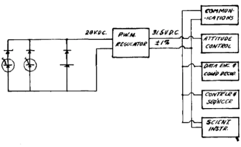
Oriented silicon photovoltaic cells provide the "basic power source for the Ranger spacecraft. An attitude control system positions the spacecraft so that solar radiation im- pinges vertically on the solar cell panels. Primary silver- zinc batteries provide power during the launch phase, prior to sun acquisition* and during guidance maneuvers when the solar radiation incident on the photovoltaic cells is inade- quate to power the Ranger spacecraft. A power logic switch- ing control draws power from the solar panel unless its out- put voltage under load becomes too low ( < 23-5 volts) to adequately power the spacecraft at which time the battery is switched in. The electrical power system block diagram is shown in Fig* 1. A booster regulator senses the nominal 28 V.D.C. system voltage and adds a pulse width modulated A..C. boost voltage which is rectified and filtered to pro- vide a 31-5 V.D.C. ±15& regulated bus voltage. Five function- ally separate overload protected static inverters provide multiple output A.C. and D.C. voltages as required for comm- unications, attitude control, scientific instruments, data processing, and telemetry. Only two of the 20 output volt- ages require a secondary feedback loop around the rectifier- filter stage to provide the accurate (±2$) required voltage regulation.
Power System Design Procedure
The principal objective of the solar photovoltaic- battery power system design is to properly size the solar array and battery. The first step in this design procedure is to determine the power versus time characteristics of the electrical loads placed on the regulated power supplies.
Then considering the efficiency of the regulated power supplies (80 - 88$), and the series boost regulator to (85 - 90$), determine the power versus time curve of the electrical power demand on the solar panel and the battery.
Although the initial Ranger spacecraft do not utilize secondary batteries, some spacecraft do; and for these designs it is necessary to increase the power capacity of the solar array to charge the battery allowing for the sun- shadow time ratio and the series efficiencies of the booster regulator (85 - 90$), the battery charger (80 - 90$), and the charge-discharge battery efficiency (80-85Î). Having determined the power source power versus time character- istics, the average power level to be delivered from the solar array is selected· This decision sizes both the solar array and the battery watt-hour capacity. Now the solar
array area is determined after making proper allowance for the factors tabulated in Fig. 2, Solar Photovoltaic Array Design Derating Factors. The "battery type and construction is selected to provide reliably the maximum watt-hour per pound performance for the required number of charge-discharge cycles. For the initial Ranger spacecraft a manually acti- vated silver-zinc battery has been selected to provide βθ watt-hour/lb. performance.
Solar Power System
The sun oriented silicon solar cells convert radiation in the 0 Λ to ΐ Λ micron wavelength region to electrical energy. Each quantum of solar radiation which is absorbed and has an energy level greater than the gap between the valence band and the conduction band generates an electron- hole pair. The electrons flow to the n region and the holes to the p region of the photovoltaic p - n junction.
The solar panels have silicon photovoltaic cells mounted on an aluminum honeycomb supporting structure as shown in Fig. 3· The aluminum honeycomb is fabricated from .0007"
thick foil by an epoxy bonding technique into a honeycomb structure 3/8" high. The aluminum facings which are epoxy bonded to the top and bottom of the aluminum honeycomb are
.012" thick. The top facing to which the cells are attached is hard anodized to provide an electrically insulated surface so that the solar cells when attached will not be short cir- cuited. The bottom facing which radiates heat to space has a brown-black anodized surface treatment which increases the emissivity to 0.85 to improve radiant heat transfer. This.
coating has been operated in a simulated space vacuum (10"^
MM. Hg) for hundreds of hours at its operating temperature (+^0° C) with no appreciable decrease in emissivity.
Silicon solar cells are used which have a three pronged grid structure to reduce internal cell resistance losses.
The sea level Earth efficiency of these cells is a nominal 12$ using recent standard measuring techniques. Currently solar cell performance measurement techniques are being cri- tically reviewed by both the cell manufacturers and space power system users. The use of a light source whose spectrum more closely simulates that of the sun than the current widely used 2800° K. tungsten lamp is required. Better primary and secondary standard cells, pyroheliometers, as well as knowledge of the sun1s cyclic spectral character- istics are required to improve the accuracy (10$) of present day solar cell performance measurements·
The gridded silicon solar cells are bonded to the alumi- num honeycomb by a room-temperature-vulcanizing silicone ad- hesive. The aluminum honeycomb is first covered with a 3 mil thick coating of epoxy and oven cured to provide additional insurance against short circuiting of the solar cells by the aluminum facing of the honeycomb supporting structure. The preparation of sligihtly roughened surfaces by abrasion or etchingt and their absolute chemical cleanliness as accom- plished by degreasing and detergent ultrasonic cleaning is vital to the successful utilization of adhesive bonding of glass and silicon. Water break and fogging tests are used to determine the presence of grease films or other surface im- purities which impair the adhesive bond.
A six mil thick glass (#0211) cover is epoxy bonded to the 1 x 2 cm. silicon solar cells to increase their emissi- vity from 0.33 to Ο.85 and consequently the radiant heat transfer which results in cooler more efficient (l/2$/°C.) operation. An anti-reflection coating is deposited on the outer surface of the glass slide. A multiple-layer ultra- violet reflecting coating is vacuum deposited on the inner surface of the glass slide to prevent ultra-violet radiation from darkening the epoxy adhesive. The solar cell adhesive bonding method described above has survived repeated thermal
cycling from +200° F. to -200° F.
The Ranger lunar probes traverse the Van Allen radiation belts in a few hours. The decrease in solar cell output due to Van Allen belt proton and electron damage is expected to be negligible. Preliminary tests roughly simulating the effect of 100 hours at ultra-violet radiation in space indi- cate that the electrical output will not decrease as much as Vfo for the ultra-violet reflecting glass (Corning #0211) covered silicon solar cells.
The Ranger solar panels have survived vibration and shock tests stage acceleration and separation shock as well as simulating the environment encountered due to rocket motor and aerodynamic vibration as the spacecraft is launched into space. The Ranger solar panels also have survived cyclic thermal shocks simulating sun to shadow transitions as well as humidity testing to check the ability of the solar panel adhesive bonds to survive the Cape Canaveral launch pad weather environment.
Batteries
Primary silver zinc batteries were selected for the Ranger power system instead of secondary batteries in order
to maximize the system watt-hour /lb. performance. Manually activated primary silver zinc batteries as are planned for Ranger will deliver conservatively βθ watt-hours/lb. for the required discharge times. Manually activated nickel-cadmium or silver-cadmium secondary batteries will deliver 10 to 15 watt-hours/lb. Since not more than 3 discharge periods are required^ the primary battery system will be both lighter in weight and more reliable because the complexity of battery charging controllers and switches is eliminated. The first two Ranger flights will carry a 7000 watt-hour 120 lb.
battery which is capable of powering the entire spacecraft without any power from the solar panels for more than 35 hours. Mission requirements dictate that the primary battery weight be reduced on the next three flights to 35 pounds pro- viding only 10 hours of operation. The batteries will be located within the spacecraft so that their thermal environ- ment will be nearly room temperature (+75° F ) , regardless of the orientation of the spacecraft or the rate of battery power drain. No heaters are provided for the batteries.
The potassium hydroxide electrolyte is considered adequate to accomplish internal sterilization so that no thermal soaking at +125° C or exthylene oxide gas treatment is re- quired.
Power Switching Logic
The first two Ranger spacecraft will use diodes to per- form the logic and switching from the solar panels to the battery energy source. This simple technique is the most reliable; but it is slightly wasteful of battery energy capacity. However> this diode power switching design is optimum for the first two Ranger flights because of its greater reliability and battery capacity is substantially in excess of that considered necessary to provide the minimum operating flight time for a successful scientific mission.
As shown in Fig. h it will be necessary for the battery to be slightly discharged to remove the peroxide peak and a
small (milliampere) continuous drain may be required to main- tain the proper battery and solar panel output voltages as required for logic switching. The internal impedance of the Ranger 1 and 2 battery is about 0.05 ohms and the maximum current that could be drawn by the system is 7 amps creating an internal voltage drop of 0.35 volts. The maximum voltage differential required to accomplish power switching is 0-35 + O.7O V diode drop. With no load on the battery its output voltage will rise so that it is necessary to place a small continuous drain on the battery when comparative power source voltage switching logic is used. For Ranger flights 1 and 2 the battery is designed to operate for 35 hours of
the 66 hour flight time; and the comparative power source voltage switching logic method consumes 3.6^/hour of the available energy. For Ranger flight 3* h a.nd 5, the battery is designed to operate for only 10 of the 66 hours flight time and could possibly use up its entire energy capacity in 28 hours merely to provide adequate current drain to accom- plish the power logic switching function. Therefore, it is obvious that a better method must be found.
The battery switching could be accomplished on an abso- lute rather than a comparative voltage basis; that is* when- ever the output voltage of the solar panel fell below a pre- determined value as established by a zener diode reference the power system would be switched to the battery. At the same time a dummy load of greater power demand than the largest expected will be connected to the solar panels. Now the power system could switch from the battery to the solar panel on a comparative voltage basis, but from the solar panel to the battery only on an absolute voltage basis. This method eliminates the need to place a power dissipating dummy load resistor across the primary battery.
Regulated Power Supplies
As shown in the electrical system block diagram, Fig. 1, a pulse-width-modulated signal is added to the D.C. voltage from the power sources. This FWM voltage is rectified and filtered and regulated to 31.5 volts ±1$. This 31.5 volt regulated bus voltage is distributed to five functionally separate static inverter multiple output voltage regulators;
for communications, attitude control, data encoder and command decoder, controller and sequencer, and scientific instruments. Only two of the twenty output voltages require regulation better than a few percent and necessitate the use of additional feedback loops around the rectifier-filter units. Each functionally separate voltage regulator has automatic short circuit protection and is designed to accept but not generate by conduction or radiation audio or R.F.
pickup, noise, or transients into the electrical power system. The secondaries of all the 20 voltages are floating with respect to their primaries so that individual function- al systems can be grounded by a return wire as may be re- quired without creating multiple path ground loops.
Summary
The salient points of the Ranger lunar spacecraft elec- trical power system are:
1. Two 10 ft. oriented silicon solar cell panels which each deliver 90 watts in space. 6 mil glass slide covers with an anti-reflection and ultra-violet reflecting filter are epoxy "bonded to the cells.
2. A manually activated primary silver zinc battery for launch and maneuver operation.
3- A simple diode power switching system is used on the initial 2 flights. A more complex logic and switching sys- tem is required for the latter 3 flights to eliminate con- tinuous trickle battery drain.
k. A pulse width modulated boost regulator provides a re- gulated 31.5 volt D.C. ± 1$ spacecraft bus.
5. Five functionally separate static inverter regulated power supplies are used to supply communications, attitude control^ data and command processings as well as the scien- tific instruments. Each functionally separate power supply is short circuit protected. The elimination of ground loops, audio and RF conducted and radiated noise has been carefully considered in the spacecraft electrical power system design.
f/çatff A/a /
/Ù/V< /42 £LÎCT£/C/?L ßLOC£ Û//9G&1M
Item Derating Percent 1.
2.
3. k.
5- 6.
7. 8.
10.
11.
12.
13.
Solar constant
Solar constant measurement error (2$) Semi-annual variation in solar constant (l.
Nominal photovoltaic conversion efficiency Adjustment for 6000°/c. Light source from
2800° K. test light source Temperature rise
Glass slide reflectance
Ultraviolet glass and adhesive darkening (67 hours)
Micrometeorite damage (67 hours) Radiation damage due to Van Allen "belt
protons and electrons (67 hour lunar trajectory) Cell to cell matching loss Module to module matching loss Blocking diode forward drop
if) 1
2$90$
15/0
9% %
Negligible Negligible
2%
2%
2.5%
Figure 2. Solar Photovoltaic Array Design Derating Factors
26
OO*"&CAS3 fibtu) sure
i/ir*wiour ttFiecTfON FÛTS*
mXY /3PU£S/\/£
SJUCON PfiùTÛ'VOLTAÎC C*CL
£POXY WSt/ÙATMa CMT/M M2"THtCÊC M*£P AitfifitZePAli/M.
ALUML flONCYCOMB
ΜβΗ g Ajvopuep .on"Amt*.
FIGUR* No. 3 SOLAR FAMG-L CROSS 5BCT/ON
VOLTS y
S%* SoLte PweL
44 40 56 32 Wi 24 20 16 12 S 4 0
-zr«
vL
/- o/ot
/ /
^ ' / /
Λ / ' 3 \/.
\ \
1_
\4 6 3 /Ù IZ Mars
p.c.
β/ιττεζν
Au
32 OA 2 *
/*
8
o *
V V ^ν^ 2*. r i : - rc/u to*£> - e*r* î&*\
\ \
/0 JS 20 2£ SO SS 40
FJGUZE
h/o. 4 SoLfieP/QueL ΦΒ/ιττεζΎ Cwe/KreG/sr/cs
27