SEALED raCKEL-CATMIUM, SILVER -САЕКЕШ^АСШ SILVER-ZINC BATTERIES Paul J . Rappaport* and Arthur M. F r i n k J r . *
U. S. Army E l e c t r o n i c s Research and Development Laboratory.
F o r t Monmouth, N. J . A b s t r a c t
This paper presents the latest "state of the art" on three hermetically sealed rechargeable battery systems and their application as energy storage devices in satellites and other space vehicles. The areas covered include the following:
l) cell reactions, 2) theoretical and practical energy densities, 3) construction features, h) performance data, and
5) further areas for investigation.
This paper will present a brief survey of the present state of the art of three hermetically sealed rechargeable battery systems and their application as satellite energy
storage devices» The three systems covered are nickel-
cadmium, silver-cadmium, and silver-zinc. The development of the nickel-cadmium battery in a sealed construction within the past 10 years and the more recent design of the two silver oxide systems in the sealed construction have made it possible to use or consider using these cells in satellites where unattended long-life operation is required. The following areas will be covered: l) cell reactions, 2) theoretical and actual energy densities, 3) construction features, and
k) performance data.
Presented at the ARS Space Power Systems Conference, Santa Monica, California, September 25-28, 1962. For the information included in this paper, acknowledgment is made to the following organizations: Boeing Airplane Company, Cook Electric Company, Delco-Remy Division of General Motors Corp., The Eagle-Picher Company, Electric Storage Battery Company, Gulton Industries, Inc., Sonotone Corp., Telecomputing Corp., Yardney Electric Corp., and the Government sponsors, the Air Force and the U. S. Army Signal Research and Development Lab- oratory.
^Chemical Engineer.
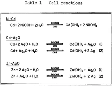
The basic cell reactions for the three systems are shown in Table 1, Although there still exists some doubt as to the composition of the charged positive active material in the nickel-cadmium system, the general 1 y accepted form is nickelic oxyhydrate (NiOOH). In the sealed cell design, the oxygen evolved at the positive plate during charge is reduced electrochemically at the negative plate, and no hydrogen is evolved at the negative plate because this plate is never charged fully« Consequently, no excessive internal pressure is built up within the cell, thus permitting its operation as a sealed cell«
The cell reactions for the two silver oxide systems are essentially the same, except that in one case cadmium is converted to cadmium hydroxide on discharge and in the other case zinc is converted to zinc hydroxide. The reactions are shown in two steps to indicate that the divalent silver oxide is first reduced to monovalent silver oxide and then on con- tinued discharge it is further reduced to silver metal« These two systems operate as sealed cells because they can be
charged with practically no oxygen evolution at the positive plate or hydrogen evolution at the negative plate« However, there remains some question as to whether under these
conditions a full charge is achieved«
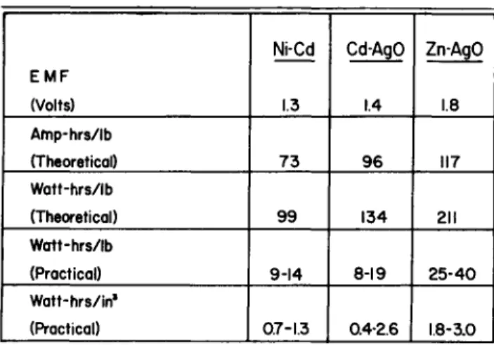
Table 2 shows the theoretical energy densities for the three systems and the range of practical energy densities thus far realized in the sealed cell designs« The theoretical energy densities are based on the equations shown in Table 1 and emf fs shown in Table 2« The practical energy densities are based upon the performance available at a five hour dis- charge rate at 8o°F« A range of values is shown because the practical energy density depends upon the size or ampere hour capacity of the cell and also upon the materials of construc- tion of the cell« The range of values for the silver-cadmium cells is considerably lower than what has been obtained with vented cells because the largest cell on which data are presently available is only 15 ampere hours, and because in the design of some of these cells much space and weight is taken up by the use of a thick resin coating around a plastic cell case as a means of sealing the cell«
The basic differences in construction features of the sealed nickel-cadmium cell as compared to the vented cell are in the separator materials, the electrolyte volume, the cell case material and configuration, and the plate configuration.
The conventional sintered carbonyl nickel plaque impregnated with the active materials is being used almost exclusively in
the sealed cells. There are three plate configurations,
namely, the standard flat rectangular plate used in rectangular and the larger cylindrical cells, the spirally wound plate used in the smaller cylindrical cells, and the flat disks used in the smallest cylindrical or button type cells. The plate thicknesses vary from about 0.017 - 0.085 inches, the thicker plates being used in the button type cells that are essentially for low drain applications. The cylindrical shaped cells have been used wherever possible because they make better pressure vessels than the rectangular cells, and therefore thinner and lighter cases can be used than with rectangular cells. The case materials all have been metallic rather than plastic, nickel plated steel and stainless steel being used most extensively.
As in vented cells, the electrolyte is a solution of potassium hydroxide, approximately 31$ by weight. An import- ant difference, however, is that practically no free electro- lyte is present in the cells, only enough being added to fill the pores of the plates and separators. This "electrolyte starved" condition is necessary to allow the oxygen to reach the negative plate more readily and thus increase the rate at which it is reduced.
The separators used in the sealed nickel-cadmium cell are sheets of felted or nonwoven absorbent materials to hold a maximum amount of electrolyte within the pores and at the same time permit ready access of the oxygen from the positive plate through the separator to the negative plate. Initially, regenerated cellulose materials were used, but it was found that these materials mercerized in the KOH electrolyte at temperatures above 100°F with resultant cell failure due to shorting. Felted noncellulosic materials such as nylon and polypropylene have better resistance to hot alkali and are now most commonly used.
The earliest cells, which were all cylindrical, were sealed by rolling the edge of the can over a plastic grommet such as nylon or teflon onto the cover. The can served as one terminal and a button welded to the covers was the other terminal, the plastic grommet providing electrical insulation between the two. Since this type of seal resulted in some electrolyte and gas leakage, it was decided that, to use these cells in satellites where unattended long-life was required, a better seal was necessary. The cell covers were welded to the cans, and one or both terminals were brought through the cover and insulated from the cover either by a
glass-to-metal, a ceramic-to-metal, or a plastic seal such as teflon* None of these seals is completely satisfactory, and this is one of the major problem areas in the three types of sealed cells.
The construction features of the two sealed silver oxide cells will be discussed together since they are similar in many respects. The plates for these cells generally are made by pasting the powdered metals (cadmium, zinc, or silver) or their oxides on suitable metal grids, drying and sintering, as necessary, and finally pressing. In some silver-cadmium cells, both positive and negative plates have been prepared by impregnation of sintered carbonyl nickel plaques, similar to those used in nickel-cadmium cells.
The separator used in the silver oxide systems, in
addition to absorbing electrolyte to keep the plates wet, must resist oxidation by the silver oxid.e plate and also minimize migration of silver from the positive to the negative plate.
To accomplish these functions, a multilayered separator sandwich is used with felted absorbent materials, such as nylon, dynel, or cellulose, placed adjacent to the plates and several layers of film type materials, such as sausage casing, cellophane, irradiated cellophane, and ion exchange membranes, between the absorbent layers. The more separation used, the greater will be the cycle life, but at a sacrifice in energy and power outputs and in overcharge capability.
The electrolyte is again an aqueous solution of potassium hydroxide, but the concentration is in the range of kO-^Ofo by weight since the silver migration is less at the higher concentrations. In the silver-zinc cells, the electrolyte is saturated with zinc oxide to reduce the dissolution and gradual disintegration of the negative plate with cycling.
This negative plate disintegration and shorting due to zinc treeing and silver migration are the main causes for the limited cycle life of the zinc-silver oxide cell.
Both silver cell types have been made in epoxy resin potted rectangular plastic cell cases. The silver-cadmium cell also is made in rectangular and cylindrical stainless steel cans with teflon or other plastic terminal seals. The silver-zinc cell also has been built in molded nylon cases with a metal terminal to plastic seal.
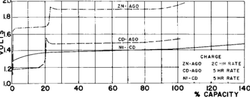
Figures 1 and 2 show typical charge and discharge curves of the three sealed cells. In the two silver oxide cells,
there is a two-step voltage on "both charge and discharge, due to the silver oxide plate, with the levels being affected Ъу the plate construction, separation, charge, and discharge rates. Since the nickel oxide plate starts to evolve oxygen before it is fully charged, the nickel-cadmium battery requires about a 25-hOf> overcharge to fully charge it. The two silver oxide cells reportedly are charged fully with only about a 3-5$ overcharge. On the other hand, the nickel- cadmium sealed cell can be charged and continuously over- charged at much higher rates than the silver oxide cells because it is better able to recombine the oxygen evolved on
charge and overcharge. At room temperature, nickel-cadmium sealed cells can be continuously overcharged at a 5-10-hr rate whereas the maximum continuous overcharge rate for the sealed silver oxide cells is in the range of the 100-200-hr rate.
Although good overcharge capability is desirable, the sealed silver-oxide cells still can be used in unattended operations such as satellites by limiting the end of charge voltage. In this way, the cells can be fully charged while practically no gases are evolved. At room temperature, the limiting voltage for the silver-cadmium cell is about 1.55-l»6o v, whereas for the silver-zinc cell, it is about 1.95-2.00 v.
Since one of the most important applications for sealed rechargeable cells is in satellites, practically all of the cycle life data obtained to date are under satellite cycling conditions. Some of these data are summarized in Tables 3-5«
A plus (+) sign next to the number of cycles to failure indicates that these tests are still running. Since the data presented were obtained from various organizations under differing test conditions and with differing criteria of failure, absolute conclusions within a system or comparisons between systems cannot be drawn. However, certain trends are indicated. In the case of the nickel-cadmium cells, at any temperature, the number of cycles obtained decreases as the depth of discharge increases. This is most likely true of the silver oxide cells also although the data available are not as conclusive. Another trend is that, at any one depth of discharge, the number of cycles available is reduced consid- erably at temperatures above and below 75°F. This is shown by the data available for the nickel-cadmium and silver-zinc cells. It is most probably true for the silver-cadmium cell as well, although only 75 °F data have been obtained thus far.
The 29,000 cycles obtained to date for a nickel-cadmium cell discharged to a 7$ depth at 75°F represent only one cell, but are presented to indicate the capability of this system. This cell still is giving satisfactory performance after 5-1/2 years•
It can be said that the state-of-the-art of hermetically sealed rechargeable cells has been advanced significantly over the last few years. Sealed nickel-cadmium and silver- cadmium cells have been and are being used as satellite power supplies, and sealed silver-zinc cells are being considered for use in short term space applications where minimum space and weight are of paramount consideration. However, there are many areas of investigation remaining to improve the performance and usability of these cells, particularly as satellite power supplies. Among these areas are the following:
l) improvement of cell seals, 2) increased reproducibility of performance from cell to cell and from cycle to cycle,
3) increased energy utilization under satellite cycling conditions, particularly at temperatures above 100°F and below J*0°F, k) improved charge and overcharge acceptance for the silver-oxide systems, and 5) greater cycle life for the silver-zinc system.
Table 1 Cell reactions
Ni-Cd
Cd + 2Ni00H+2Ht0
Cd-AgO
Cd + 2Ag0+Ht0 Cd+Ag.O + H.O
Zn-AgO
Zn+2Ag0 + Ht0 Zn + AgaO + H20
W3CHQ
Cd(0H)t + 2Ni(0H)t
Cd(OH)t+AgtO (I) Cd(0H)t + 2Ag (2)
Zn(OH)t+ AgtO (I) Zn(0H)t+2Ag (2)
Table 2 Theoretical and p r a c t i c a l energy densities
EMF (Volts) Afnp-hrs/lb (Theoretical) 1 Watt-hrs/lb
(Theoretical) 1 Watt-hrs/lb
(Practical) Watt-hrs/in1 (Practical)
Ni-Cd
1.3
73
99
9-14
0.7-1.3
Cd-AgO
1.4
96
134
8-19
0.4-2.6
ZnAgO
1.8
117
211
25-40
1.8-3.0 1
Table 3 Cycle l i f e data for Ni-Cd c e l l s
NI-CD CYCLE LIFE DATA CHG/DISCHG
TIME (MIN)
55/35
55/35
55/35
6 0 * 0 6 0 * 0
DEPTH OF DISCHG
25%
50%
75%
7%
25%
TEMP,
•F
120 75 0 120 75 0 120 75 0 75 120 75
NO. OF CYCLES TO FAILURE
990-1532 1450-9375*
4 2 0 - 4 5 9 130-579 280-1168 20-52
25-150 1 30-218 1
9-18 29000+
675-2730 900-7000
Table k Cycle l i f e data for Ag-Cd c e l l s
CD-AGO CYCLE LIFE DATA 1
CHG/DISCHG TIME (MIN)
55/35 65/35 65/35 65/35 65/35
DEPTH OF DISCHG
20%
2 5 % 35%
50%
65%
TEMP,
°F
75 75 75 75 75
NO. OF CYCLES TO FAILURE
2500 7 5 0 0 * 6417-7349 3 9 7 9 - 7 3 9 8
1821
Table 5 Cycle l i f e data for Ag-Zn c e l l s
ZN-AGO CYCLE LIFE DATA
CHG/DISCHG TIME (MIN)
85/35
85/35 85/35
85/35
DEPTH OF DISCHG
21%
25%
29%
41%
TEMP,
eF
100 75 30
75
100 75 30
100 75 30
NO. OF CYCLES TO FAILURE
415-583 4-1760 122-200 219-226
3 0 2 - 4 0 0 3 0 2 - 3 4 4
122
200 2 0 0 47
100 120 140
% CAPACITY
Fig. 1 Typical charge curves
IT
«21.5
5i3
I.I oq
^«
\
ZN-
N1- CD-
AGO
CO
AGO ^ \
V
DISCHARGE S MR
RATE
20 40 60 80 100 120 140
% CAPACITY
Fig. 2 Typical discharge curves