THE BATTERY FOR THE INTERNATIONAL IONOSPHERE SATELLITE ARIEL I
Eugene R. Stroup*
NASA Goddard Space Flight Center, Greehbelt, Md.
Abstract
This paper describes the application of an improved recharge- able, nickel-cadmium battery for spacecraft. It was designed for the International Ionospheric Satellite known as the UK-1 or Ariel I. Innovations including a ceramic-to-metal hermet- ically sealed case and pellon plate separators are discussed.
The battery selected for this satellite was an early product of the joint research and development program for battery im- provement sponsored by NASA and industry. This battery incor- porated the latest advancements in the state-of-the-art for spacecraft secondary batteries at the time of launch on April 26, 1962.
I. Introduction
The environmental factors of vacuum and temperature changes peculiar to space create novel problems in the design of nickel-cadmium batteries for spacecraft.
In the development of the secondary battery for the Ariel satellite two specific areas of improvement were emphasized.
These were l) the development of a light weight, stainless steel, welded case equipped with a ceramic-to-metal hermetic seal, and 2) the design of a plate separator capable of with- standing the potassium hydroxide electrolyte environment at 60°C for a period of at least one year without failure.
Prior to 1961, cell failure rates during acceptance and qual- ification tests were extremely high. Among cells delivered to users for spacecraft applications, it was not uncommon to have shorting in one-third of the cells within 5 cycles at 50°C
because of cell separator failures. A more prevalent difficulty Presented at the ARS Space Power Systems Conference, Santa Monica, Calif., September 25-28, 1962.
^Research Engineer.
249
was encountered with the glass-to-metal hermetic seals that were found to leak in about 90% of the cells delivered for spacecraft use. Although this could have been corrected by using an epoxy material, the added weight characteristic was objectionable.
The space temperature environment was predicted to lie within the 10°C to 4-0°C range for Ariel. Environmental tests were conducted and they indicated that the S-51 battery should func- tion properly with sustained temperatures from -10°C to 60°C.
Throughout the planning stage a philosophy of redundancy was fostered because of the past history of questionable reli- ability in nickel-cadmium spacecraft batteries. The Goddard Space Flight Center is administering a NASA sponsored research and development program with industry for the advancement of the state-of-the-art of spacecraft batteries in general. Ini- tial. emphasis was placed on nickel-cadmium battery seals and separators. The battery developed for the S-51 was a by- product of this research and development effort.
II. System Requirements A. Voltage
A nominal 12-v system was chosen for the Ariel satellite power system. This was a compromise voltage level being larger than the single cell battery voltage preferred by the battery designer and smaller than the relatively high voltage values that are conventional among electronic converter designers.
B. Current
Approximately 24 load requirements in the satellite accounted for the total load of 5 w, continuous, with two minute peaks of 7 w during each orbit. The total average current from the battery to the payload was slightly less than 4OO ma at 12 v including 2-minute intervals to 600 ma.
C. Life
A lifetime of 1 yr was specified. Nickel-cadmium batteries with teflon separators had proven capability in excess of one yearTs life in 90 minute earth orbiting satellites. The Ariel cell was the result of a concentrated effort to get the most reliable and highest "usable" capacity cell possible developed for this international effort.
POWER SYSTEMS FOR SPACE FLIGHT
III. Description
The Ariel battery incorporated advancements in the state-of- the-art by improvements in both seals and in plate separators used within the cells. The cell was a 6 amp-hr, sintered- plate, nickel-cadmium, hermetically sealed, rectangular stain- less steel case variety. It has been described as an electro- lyte starved system having a minimum amount of electrolyte.
The positive terminal of each cell was encased in a ceramic- to-metal hermetic seal. The plate separators were of pellon and have been successfully operated at 60°C temperature (20°C higher than paper separator cells) while simulating the ex- pected satellite 100 minute orbital condition. The stainless steel case was closed by heli-arc welding techniques. The electrolyte was a solution of potassium hydroxide and water with a specific gravity of 1350. The cell weight was approxi- mately S oz. A single cell is shown in a photograph (Fig. l )0
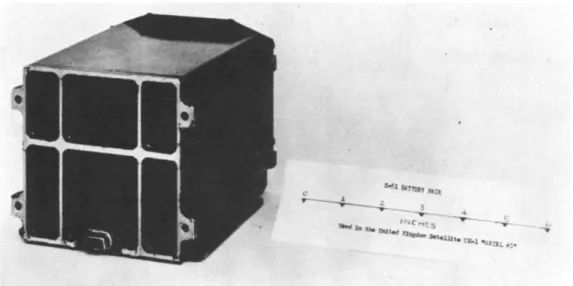
The battery package is shown in Fig. 2 along with the teflon separators used to separate the cells from each other and from the ribbed metal box containers. A sample of eccofoam used to fill the cavity between the cell tops and the cover plates is shown. Figure 3 is a photograph of the cell arrangement in the battery package showing the edges of the teflon separators sep- arating the cells, the nickel-plated steel intercellular con- nectors with expansion loops which are welded to the cell posts and the nine pin connector with dual redundancy in pin
connections.
IV. Battery Requirements A. General
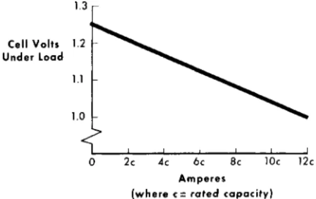
Figures 4 and 5 illustrate characteristics which were con- sidered in determining battery size and are offered here as summaries of data taken from the batteries actually used in the Ariel satellite program. It was stipulated in the basic system requirement that two batteries would be used in the satellite. One battery would provide power to the payload while the second battery would be in a standby status, under- going trickle charge, ready to be switched on if needed. The battery operating voltage limits were specified as 10 to 15 v
and the total power requirement five w.
The electronic shelf temperatures expected Inside the satel- lite were from 10°C to 40°C. To insure reliable operations the batteries were subjected to sustained temperatures from -10°C to 60° C. Figures 6 and 7 illustrate characteristic data col- lected at Goddard Space Flight Center with the batteries for anticipated conditions of orbit and loading.
251
B. Battery Size Determination
Previous satellites have employed batteries sufficiently large to limit the depth of discharge of the battery to less than 1%. The Ariel designers collected sufficient data to in- dicate that the nickel-cadmium battery could deliver more than lOfo depth of discharge for 1 yr and remain reliable. As a margin of safety, the depth of discharge was specified as 5%, and a 4 to 6 amp-hr battery was sought for the task. A newly developed 6 AH battery became available in sufficient time for test, evaluation, and qualification for flight and was procured for the satellite.
C. Availability of Batteries
Early in the program, during the planning and design period there were no suppliers of satisfactory spacecraft batteries.
That is, to say, that the batteries could not be flown as sup- plied by the manufacturer. It was necessary to encase the battery in a potting compound to prevent leaking; also, tem- peratures in excess of 100° Fahrenheit had to be avoided or the paper separators would fail causing internal shorts within the cells.
Some of the more conservative users of spacecraft cells spec- ified teflon separators to insure against shorting type fail- ures. The teflon separator cell proved to be highly successful in applications where the loading requirement was sufficiently small to limit the depth of discharge to less than 1% nominal rated capacity per orbit.
V. Acceptance and Qualification Tests
Acceptance and qualification tests developed at Goddard Space Flight Center for the Ariel battery included tests to measure cell capacities, locate physical leaks, detect electrical shorts, and measure the rate of loss of capacity during open circuit stand from the fully charged condition.
Two physical leak tests were employed as means of insuring validity of the results. The bubble test was considered ade- quate for applications involving a service life requirement of up to 1 yr. Goddard Space Flight Center studied test methods in search of a foolproof means to determine and predict the effectiveness of the hermetic seal for use in applications with lifetime requirements in excess of 1 yr. The helium leak test was considered valid if a helium leak rate less than 10"^ cubic centimeters per second per cubic centimeter of KOH solution was detected. The helium leak detector used revealed no leaks in
POWER SYSTEMS FOR SPACE FLIGHT
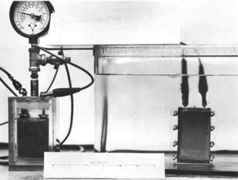
125 cells tested. These same 125 cells were next tested by the immersion bubble method and nine leakers were found. This latter test involved overcharging the cells at the 10-hr rate for 24 hr to build up internal pressures. A pressure gage fitted pilot cell is placed in series with the test cells to indicate the pressure build-up. When the pressure exceeded 50 psi, the test cells were immersed beneath a transparent so- lution and visually examined with a hand lens. Leaks were lo- cated by observing small clearly discernible bubbles escaping either in the welds of the stainless steel case, in the pinch- off tube, or in the ceramic to metal seals. The failure of the helium test was attributed to the elusive nature of helium that was inserted by the manufacturer and which presumably later
combined with the electrolyte during the overcharging to build- up internal pressures. See Fig. 8 - illustration of bubble type leak test.
Capacity tests were conducted in accordance with the manu- facturer's instructions and 30 of 125 cells yielded about 10%
less than the manufacturer's capacity rating for the cell.
Restoration of the capacities was achieved by high rate cycling employing constant potential charging.
Two of the 125 cells were rejected because of electrical shorts. These shorts were evident by excessive rates of loss of capacity on open circuit stand. A rapid test procedure for determination of electrical shorting was developed. Individual cells were discharged to zero volts and allowed to stand on open circuit while observing the recovery of the cell voltage using a high impedance voltmeter. The good cells recovered 90^
of rated load voltage within 24 hr.
A summary of the Ariel battery characteristics giving typical loss of capacity on open-circuit-stand for up to 30 days dura- tion, is shown in Fig. 9.
In order to acquire data for use in designing the battery charging and control circuitry, tests were conducted based on every conceivable flight condition. Voltage parameters for various loads and temperatures were determined and are illus- trated in Fig. 6. The voltage excursions caused by temperature changes were on the order of ICffo of the total load voltage.
The system voltage extreme excursions from the highest charge to the lowest discharge voltage points were on the order of 20fo.
It was noted that the capacity of the battery decreases rapidly during the first few weeks of shallow cycling as illustrated in Fig. 5. This reduction in capacity was corrected by constant
253
potential charging and high rate discharging. This character- istic was not critical to the Ariel since only 5% of the bat- tery capacity was required.
VI. Concluding Remarks
The Ariel was placed in earth orbit on April 26, 1962 and functioned as intended. The batteries had ceramic-to-metal hermetic seals instead of the customary sealing compound or epoxy in which earlier types were potted. The plate separators were resistant to the attack of the alkaline electrolyte at
elevated temperatures. The NASA Goddard Space Flight Center spacecraft battery research and development program, continues with efforts to provide acceptable sealed spacecraft secondary battery systems in silver-zinc, silver-cadmium, nickel-cadmium, and lead-calcium varieties. These batteries have improved seals, separators, low and high temperature performance, im- proved depth of discharge characteristics, and extended life expectancies. The Ariel power system included a battery which was one of the earliest products of this program. Figure 10 is an illustration of the complete battery package.
SPACECRAFT NICKEL CADMIUM CELL 6 A H - 1.25 V - 1.2 V AT 20 AMP
PELLON SEPARATOR - 8 OZ - KOH ELECTROLYTE
CERAMIC SEAL- STAINLESS STEEL CASE- SINTERED PLATES Used in the United Kingdom Satellite "ARIEL #Г
O
O
1 2 4
INCHES
>
n O
Fig. 1 A single cell (photograph NASA-G-62-3349). Developed under NASA/Goddard Space Flight Center spacecraft bat- tery R&D program
MCKEX CQATED IRON ^ ^ |
Fig. 2 The Ariel Satellite battery and associated equipments (photograph NASA-G-63-33S)
Fig. 3 The Ariel Satellite battery cell arrangement
POWER SYSTEMS FOR SPACE FLIGHT
1.3 r
Cell Volts 12 Under Load
0 2c 4c 6c 8c 10c 12c Amperes
(where c= rated capacity)
Fig. 4 Nickel-cadmium battery surge current voltage character- istics determined with the Ariel Satellite battery
100 i
Percent of Rated Capacity 5 0
Available
12 Time (months)
Fig. 5 Nickel-cadmium battery typical capacity decay curve resulting from shallow low rate cycling
257
Battery 13 Volts
20 40 60 80 100 Time (minutes)
_500 MA_
Charge _ 500 MA _ Discharge -One Cycle-
6 International ionosphere satellite battery voltages during simulated orbital conditions at extreme tem- peratures and average loading conditions for a single cycle during longest eclipse time
Over-Charge Amperes
10 20 30 40 50 Battery Temperature (°C) (measured at terminal post)
7 The Ariel Satellite battery overcharge current as af- fected by temperature changes with voltage limited to 1.45 v per cell
POWER SYSTEMS FOR SPACE FLIGHT
Fig. 8 The Bubble Test. Used to determine and/or locate leaks. Internal pressures were built up by over- charging. The pressurized cell is placed under a transparent nonconducting solution. Bubbles stream out of leak around the ceramic seal
100 Percent Capacity Available
10 15 20 Time (days)
Fig. 9 Loss of capacity on open-circuit stand. The Ariel Satellite battery curve showing percent capacity available
259
o
t
bJkbt^ï
^ * т »г ш^ 73
o
• «* ant«. ищйт *«**uxi* t·jç.j „
Fig. 10 Exterior appearance of one of the two Ariel batteries