APOLLO PROJECT STATUS Charles W. F r i c k1
Manned Spacecraft Center, Houston, Texas ABSTRACT
Apollo is the project of the U. S. manned space f l i g h t ef- f o r t whose objective i s to land men on the moon and return them safely to Earth. I t d i f f e r s from Project Mercury in
sophistication of maneuver and spacecraft design, since Apollo i s composed of several modules and w i l l have the capability of landing on the lunar surface. The spacecraft is the r e - sponsibility of the NASA Manned Spacecraft Center in Houston;
the launch vehicle, of Marshall Space Flight Center; and ground operational support, of several Centers and other agencies. The spacecraft proper consists of a command module, service module, launch escape system, adapter ( a l l being de- veloped under contract by North American Aviation), and a landing stage, which w i l l be either a lunar excursion module or a staged landing system for the command module. The com- mand module houses the astronauts and a l l controls and instru- mentation. The service module provides propulsion and second- ary power support for midcourse, r e t r o , and return maneuvers and for daily operations.
Almost a l l major modules are under contract. Those that s t i l l need to be started are not the pacing items.
INTRODUCTION
The Apollo program has as i t s objective the landing of the United States astronauts on the lunar surface at the e a r l i e s t possible time, limited exploration in the landing area, and return of the crew with s c i e n t i f i c data to the Earth.
I t should be noted here that Apollo is only one of the space systems involved in the U. S. national space e f f o r t which w i l l
Presented at the ARS Lunar Missions Meeting, Cleveland, Ohio, July 17-19, 1962.
^Manager, Apollo Spacecraft Project Office.
lead to further manned explorations of our universe. Mercury was the f i r s t in this program. I t is interesting to compare the c a p a b i l i t i e s of Mercury and Apollo, as shown in Table 1 . Of particular interest is the degree of sophistication in maneuvering and in spacecraft environment. The Apollo system w i l l be capable of the large midcourse corrections required for cislunar portions of the t r a j e c t o r i e s . In the v i c i n i t y of the moon, the Apollo system is also capable of placing an astronaut on a landing s i t e on the moon.
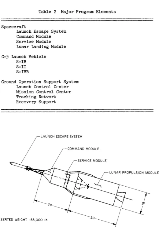
The present discussion i s concerned with only one portion of the Apollo system. Table 2 shows the major elements of the Apollo system, the management of which is directed by D.
Brainerd Holmes through the Office of Manned Space F l i g h t . The Apollo system has three major elements: the spacecraft, the launch vehicle, and the ground operational support system.
The Office of Manned Space Flight has delegated responsibility for the spacecraft to the Manned Spacecraft Center, Houston, Texas. Responsibility for the C-5 launch vehicle has been delegated to the Marshall Space Flight Center at Huntsville, A l a . ; the responsibility for the ground operational support
system i s distributed among the Launch Operations Center at Cape Canaveral, F l a . ; the Goddard Space Flight Center, Greenbelt, Md.; the Jet Propulsion Laboratory, Pasadena, C a l i f . ; and the Manned Spacecraft Center at Houston. An im- portant portion of the ground operational support system i s supplied by the Department of Defense, p a r t i c u l a r l y recovery support.
DISCUSSION
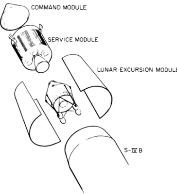
This paper covers only one element of the system: the spacecraft, which i s shown in the launch configuration in F i g . 1 . The portion of the t o t a l spacecraft which includes the launch escape system, the command module, the service module, and the adapter has been contracted to the North American Aviation I n c . , Downey, C a l i f . A contract f o r the landing stage has not yet been issued; and, in f a c t , at this point, a decision has not; yet been reached as to whether de- scent to the lunar surface w i l l be accomplished by braking from lunar orbit and providing a soft touchdown for the en- t i r e spacecraft or whether descent to the surface of the moon w i l l be made through the use of a lunar excursion module which w i l l permit the astronauts to leave the command and
service module in lunar o r b i t . F i g s . 1 and 2 show a compari- son of the two spacecraft required for descending to the sur- face of the moon by either method.
SPACECRAFT ELEMENTS DESCRIPTION
At this point the hardware now currently under development by North American Aviation Inc. w i l l be discussed. F i g . 3
shows that portion of the spacecraft f o r which NASA has con- tracted with North American. The launch escape systems pro- vide a means for l i f t i n g the command module away from the booster in the event of a booster f a i l u r e , either on the pad or during the boost phase (through separation of the S-l s t a g e ) . The command module i s the primary command stage f o r the astronauts and provides a l l the controls, instrumentation, and navigation equipment. The service module includes the energy source and rocket motor for making midcourse correc- tions, retromaneuver into lunar o r b i t , and for acceleration back into the return or trans-Earth t r a j e c t o r y . The service module also contains the fuel c e l l power source as well as the hydrogen/oxygen storage f o r this power source.
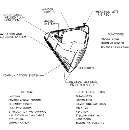
F i g . It shows a schematic of the command module which gives the crew stations during the f l i g h t to the moon and return.
There i s a couch position for f l i g h t control in which the astronaut has before him displays which indicate his position in space. Another couch position f o r sleeping i s achieved by moving the center of the three couches to an extended position.
The command module is aleo f i t t e d with an extended a i r lock which permits egress of the crew without depressurizing the cabin.
F i g . 5 shows a more detailed view of the command module, p a r t i c u l a r l y the structure which i s double walled, the out-
side of which i s f i t t e d with ablation material to provide a heat shield f o r re-entry. During the terminal phases of the return f l i g h t from the moon, the service module is jettisoned, and only the command module returns to the surface of the Earth. The command module i s so designed that the center of gravity is offset from the axis of symmetry so that the space- craft i s balanced in a condition in which there i s a l a t e r a l force vector. This force vector can be used f o r l i f t i n g r e - entry or f o r controlling the l a t e r a l dispersion during the re-entry by operating the reaction control system to rotate the command module so that t h i s force vector l i e s in the r e - quired direction. B a l l i s t i c re-entries can be made by spin- ning the command module which then enters along a h e l i c a l path.
Navigation of the spacecraft i s done through optical fixes obtained through instruments as shown in F i g . 6. The space- c r a f t contains both a sextant and a scanning telescope. The
information obtained by these optical devices flows into a computer which makes a comparison of the true position in space with that which the spacecraft should have to be on a correct t r a j e c t o r y . I f the trajectory i s shown to be in error, the spacecraft i s positioned to make a velocity correc- tion with the service module propulsion system. I t i s neces- sary, i f such a correction i s required, to orient the space- craft appropriately. The orientation is read from the com- puter, and corrections in orientation are made with the r e - action control system on the service module. This control system uses an Earth-storable hypergolic fuel and i s actuated by a logic sequence which i s a part of the s t a b i l i z a t i o n and control system. The service module engine which makes the midcourse corrections i s shown schematically in F i g . 7· This engine also uses Earth-storable hypergolic fuels and u t i l i z e s a single, gimballed, ablative nozzle.
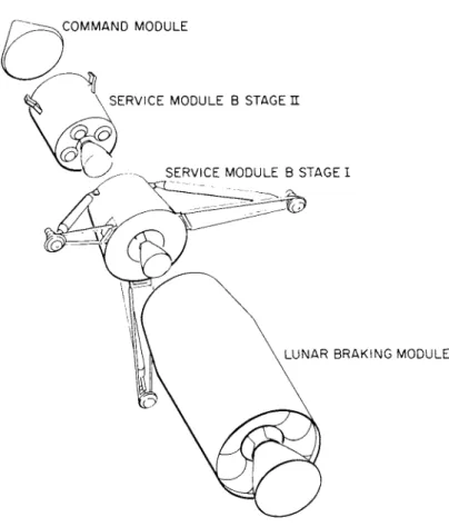
The major piece of hardware yet to be contracted for w i l l either be the lunar excursion module, shown as an a r t i s t ' s con- ception in F i g . 8, or the lunar braking module shown in F i g . 9 · In the former case, that of lunar o r b i t rendezvous, a direct descent is made with a single C- 5 , and injection into the translunar f l i g h t is made with the S-IVB stage. With the spacecraft as shown in F i g . the spacecraft and injection station are assembled in Earth orbit by rendezvousing two C-5 payloads. A detailed study of these two methods i s currently underway under the direction of the Office of Manned Space F l i g h t . Work i s being pursued both at the Marshall Space F l i g h t Center and at the Manned Spacecraft Center. Recom- mendations and results of analyses have been submitted r e l a - tive to these two modes.
PARTICIPATING ORGANIZATIONS
One f i n a l point of interest concerns the distribution of the prime e f f o r t centers f o r the Apollo Spacecraft Project as cur- rently contracted. The principal contractor f o r the Apollo Spacecraft is North American Aviation I n c . , Downey, C a l i f . , at which s i t e there is a Resident Apollo Spacecraft Project O f f i c e . A suborbital booster i s under development by General Dynamic s/Convair, San Diego, C a l i f . , f o r the qualification t e s t program. These tests w i l l be performed at White Sands Missile Range, N. Mex., where there i s a Resident Apollo Spacecraft Project O f f i c e . The focal point of spacecraft direction i s at the Apollo Spacecraft Project Office at the Manned Spacecraft Center, Houston, Texas. There i s , of course, a strong interface with the booster "which i s carried on at the Marshall Space Flight Center. The Project Office
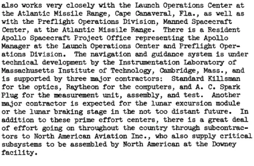
a l s o works very c l o s e l y with the Launch Operations Center at the Atlantic M i s s i l e Range, Cape Canaveral, F i a . , as well as with the P r e f l i g h t Operations Division, Manned Spacecraft Center, at the Atlantic Missile Range. There i s a Resident Apollo Spacecraft Project Office representing the Apollo Manager at the Launch Operations Center and P r e f l i g h t Oper- ations Division. The navigation and guidance system i s under technical development by the Instrumentation Laboratory of Massachusetts I n s t i t u t e of Technology, Cambridge, Mass., and i s supported by three major contractors: Standard Killsman for the optics, Raytheon f o r the computers, and A . C. Spark Plug for the measurement unit, assembly, and t e s t . Another major contractor i s expected f o r the lunar excursion module or the lunar braking stage in the not too distant future. In addition to these prime e f f o r t centers, there i s a great deal of e f f o r t going on throughout the country through subcontrac- tors to North American Aviation I n c . , who also supply c r i t i c a l subsystems to be assembled by North American at the Downey f a c i l i t y .
Table 1 Capabilities of Mercury and Apollo
Capability Crew
Mission duration
Mercury Single 4 - 1 / 2 hr
Re-entry velocity, f t / s e c 26,000 Maneuvers Attitude only
Landing Spacecraft environment
Earth only Pressure suit
Apollo Multi-man
2 wk 36,000 Attitude Midcourse
Lunar Earth & moon
Shirtsleeve
Table 2 Major Program Elements
Spacecraft
Launch Escape System Command Module
Service Module Lunar Landing Module C-5 Launch Vehicle
S-IB S - I I S-IVB
Ground Operation Support System Launch Control Center Mission Control Center Tracking Network
Recovery Support
F i g . 1 Apollo spacecraft configuration
Pig. 2 Apollo spacecraft and launch vehicle
Fig. 3 Apollo spacecraft at separation
γ- AIRLOCK CLOSED PRIMARY DUTY STATION —ν \ DISPLAYS PRESSURE CABIN \\ AND CONTROLS —j
J
HEAVY EQUIPMENT THIS / / UAIL,^ SIDE TO SHIFT CENTER / τΑ-151.5" - OF GRAVITY ' SLEEPING—/ NORMAL INGRESS AND EGRESS- Fig. k Command moduleINNER CABIN WELDED ALUM HONEYCOMB
NAVIGATION AND GUIDANCE SYSTEM
WINDOW
COVERS REACTION JETS
(16 REO)
FUNCTIONS
HOUSES CREW COMMAND CENTER R E - E N T R Y AND LANDING
COMMUNICATION SYSTEM
SYSTEMS
LANDING
ENVIRONMENTAL CONTROL R E - E N T R Y POWER HEAT PROTECTION
STABILIZATION AND CONTROL NAVIGATION AND GUIDANCE S T R U C T U R A L
COMMUNICATION
BATTERIES
ABLATION MATERIAL ON OUTER SHELL
CHARACTERISTICS
PARACHUTES S H I R T S L E E V E
S I L V E R ZINC B A T T E R I E S A B L A T I V E
REACTION S T E L L A R I N E R T I A L HONEYCOMB
T E L E M E T R Y , VOICE, T V
Fig. 5 Command module elements
F i g . 6 Spacecraft n a v i g a t i o n operations
DUTIES • EARTH-ORBIT RETROGRADE • MIDCOURSE VELOCITY CHANGES • EXTRA ATMOSPHERE ABORT
Ç
~~jTj O j/fT\ ^
• LUNAR ORBIT (PHASE Β) \ / / ^^J^l / • LUNAR LAUNCH \ / /( / // \ SYSTEM DESCRIPTION \ //C I • EARTH STORABLE, HYPERGOLIC Ν, / ^ '/^^ß • SINGLE, GIMBALED ENGINE ^^-^Δ / • ABLATION COOLED y/^^J • PRESSURE FED • CONTRACTOR, AEROJET Fig. 7 Service propulsion systemFig. 8 Component separation - Apollo lunar o r b i t rendezvous
Fig. 9 Component separation - Apollo direct landing