TECHNOLOGY OF LUNAR EXPLORATION
MANNED SPACE FLIGHT Norman J. Ryker Jr. 1
North American Aviation Inc., Downey, Calif.
ABSTRACT
This paper discusses the effect of four major factors upon the design of spacecraft for several different space missions.
The factors are the space environment, the performance require- ments, the operational phases, and the time to survival, each
of which varies considerably for the selected missions. As a result, the spacecraft configuration, its subsystems, and the design philosophy differ markedly.
The first three of these factors are similar in nature to those which the aircraft designer has previously encountered.
The fourth is more unfamiliar to him, and coping with it as with any new problem, tends to add additional weight and com- plexity to the spacecraft that may, with greater experience and knowledge, be unnecessary. However, even as more experi- ence is gained, the detail design of spacecraft hardware will always reflect the requirement to provide a means of safely returning to Earth in the event of an emergency. This emer- gency return time, or time to survival, is as much as 3-l/2 days for lunar missions and as much as one year for Mars and Venus missions.
INTRODUCTION
Today, scientists and engineers are reducing to reality man's long dreamed-of flights into space and visits to the moon and other planets. This is being accomplished, not merely to satisfy man's curiosity, but to develop useful sys- tems that will provide fundamental scientific data to increase our understanding of the universe. In satisfying the
scientist's requirements while constraining the hardware design to fit within practical physical and schedule limita- tions, the aerospace engineer is faced with new and unique problems. These problems, however, are related to those
Presented at the ARS Lunar Missions Meeting, Cleveland, Ohio,
July 1 7 - 1 9 , 1962·
^ s s ' t Chief Engineer, Apollo, Space and Information Systems Division.
Ν. J . RYKER JR.
previously encountered with aircraft and missiles.
As more is learned about spacecraft design, it becomes evident that spacecraft must be divided into classes, as air- craft were, rather than to regard them as one general category of manned space vehicles. Major differences in configuration and systems are evident in the four manned spacecraft now under development, Mercury, Dyna Soar, Gemini, and Apollo. The X- 1 5 rocket aircraft, which has achieved an altitude of kj miles and has some attributes of a spacecraft, is an entirely
separate class. However, each is currently adding to our store of detailed design knowledge for application to future, more advanced space missions.
Four major constraints for successively more ambitious missions are considered in this paper to illustrate the effect of the mission on spacecraft design. The constraints are the mission environment, performance requirements, mission success, and crew survival. Five space missions were selected for con- sideration: a short duration, Earth-orbital mission (similar to that of the Mercury); an Earth-orbital laboratory; a
circumlunar mission; a lunar landing mission; and a Mars or Venus fly-by. Only the Earth-orbital, the space laboratory, and the lunar-landing missions will be considered in detail.
fflSSIONS
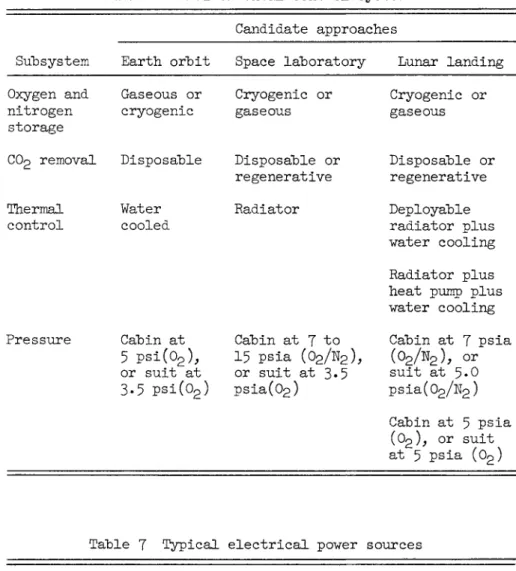
Before discussing the spacecraft in detail, a brief orienta- tion of essential mission phases is in order. Four of the five missions are shown in the trajectories in Figs. 1-4. The fifth mission, that of the space laboratory, would follow a
trajectory similar to that in Fig. 1 for Earth orbit but for a flight of up to a year duration. In the Earth-orbital
missions, as for all of the missions, the assumed launch point was Cape Canaveral. A two-stage booster would place the space- craft in an inclined orbit. After the desired number of orbits, the Earth-orbital spacecraft would eject from orbit over the Pacific Ocean or the southwest portion of the United States, enter the atmosphere over the southern United States, and finally be recovered in the ocean off Florida. The approximately 100-naut mile orbital altitude for these missions would be below the Van Allen belt to minimize the radiation exposure of the crew.
The circumlunar mission, Fig. 2, was also based upon launching from Cape Canaveral using a two-stage booster to place the spacecraft into a parking orbit with a nominal alti- tude of 100 naut miles. At the appropriate time in the
trajectory, the spacecraft would be injected into a
TECHNOLOGY OF LUNAR EXPLORATION
translunar trajectory by ignition of a third-stage booster.
The translunar coast period would be maintained until a mid- course correction was made. The spacecraft would then coast until passing behind the moon with a perilune of approximately 100 naut miles. Two missions are possible at this point, either injection of the spacecraft into a lunar orbit with a later rejection for return to Earth or a continuation in the circumlunar trajectory returning to Earth. The returning spacecraft would enter Earth1s sensible atmosphere at an alti- tude of about 400,000 ft. A lifting entry could be achieved with a lift-drag ratio of about 0 . 5 . Recovery would again occur in the ocean off Florida.
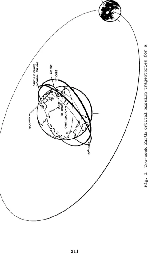
For the lunar landing mission, Fig. 3> the launch and
injection into a translunar trajectory would be similar to that for a circumlunar mission. However, upon reaching perilune, the spacecraft would be injected into a nominal 100-naut mile altitude lunar orbit in which the spacecraft would remain until the crew elected to land. The spacecraft would then make a Hohman transfer to a low-altitude perilune on the Earth side of the moon. At this point, the terminal retro maneuver would be executed to perform the lunar-landing maneuver. A three- day stay was assumed in Fig. 3· The lunar launch would occur at the illustrated third lunar position. A lunar boost would place the spacecraft in a circular lunar orbit with a subse- quent injection into the transearth trajectory occurring as the spacecraft emerged from behind the moon. The spacecraft would then enter the atmosphere over the Pacific Ocean at a 400,000-ft altitude. With a lifting trajectory, its recovery would occur in the ocean off Cape Canaveral. A three-day stay on the lunar surface would result in a nominal 8|--day mission.
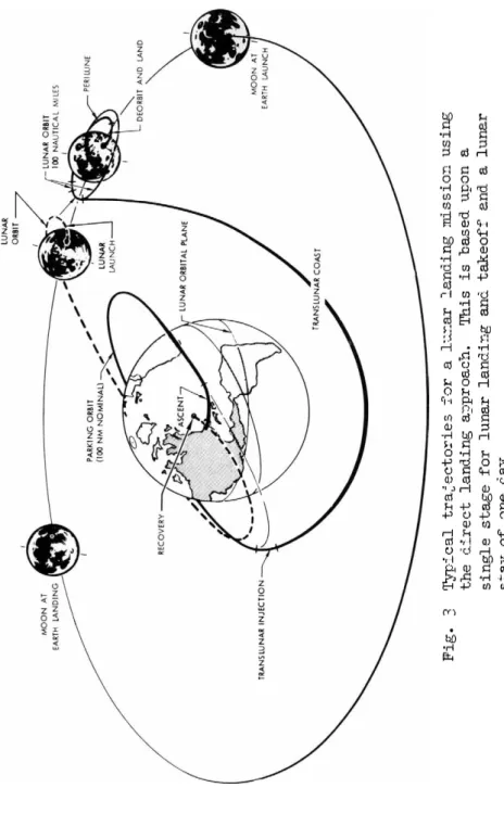
For the manned Mars and Venus fly-by mission, Fig. 4, the spacecraft would be boosted into an elliptical solar orbit having a period equal to the Earth orbital period. By launching at appropriate times, it is possible with this type of trajectory to fly past both Mars and Venus and return to Earth one year later. The orbit shown has a perihelion about one half of the nominal radius of the Earth orbit, which is the maximum compatible with an aphelion slightly greater than the nominal radius of the Mars orbit.
Although this does not result in a minimum velocity trajec- tory, it does enable the spacecraft to be placed in the Mars- Venus trajectory and to rendezvous with Earth one year later with only relatively small midcourse corrections.
ENVIRONMENTAL CONSTRAINTS
Many of the problems discussed at length in the design of
Ν . J . RYKER JR.
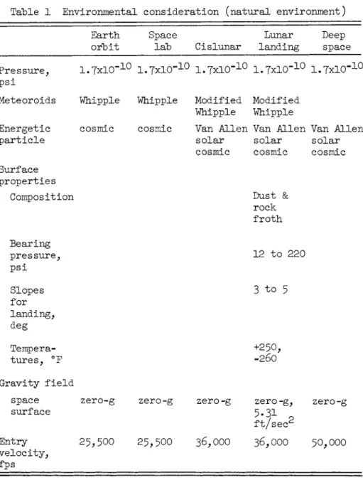
the spacecraft have dealt with the harsh, unnatural environ- ment for man which exists in space. Some of these are identi- cal for the rudimentary Earth-orbital mission and for the more ambitious planetary missions; others vary greatly. Although these environmental constraints have been well recognized for some time, the author would like to emphasize those which are currently confronting the spacecraft designer with troublesome but important decisions. As illustrated in Table 1, the ambient pressure in space may not vary sufficiently for
missions to the near planets—at least the variations will have little effect on spacecraft— until attempts are made to enter the atmosphere of other planets. The micrometeoroid distri- bution, however, may vary greatly in the vicinity of planets, and meteoroid showers may be encountered on longer missions.
The micrometeoroid environment is currently a major unknown, even for Earth orbit, and is one that could seriously affect the spacecraft weight. Excellent analytical and experimental analyses of the impact phenomena have been and are being made.
A designer using the available data and choosing to provide protection with a high degree of confidence for long duration mission can greatly increase the spacecraft weight, whereas the designer who chooses a good structural configuration for protection but does not attempt to protect against pessimistic estimates can achieve a design that is compromised but little.
Which approach is correct can be debated endlessly. What the designer needs is an accurate model of the micrometeoroid environment. Until it is available, he must weigh the cost of protection against the most realistic appraisal of the result of a penetration and make his decisions accordingly.
Another major unknown is the radiation environment. For low-altitude Earth-orbital missions, this is relatively unim- portant because the spacecraft is below the Van Allen belt and can return to Earth in a short time if necessary. For the more ambitious planetary missions, more severe environment because of solar flares, transit of the Van Allen belts, and long mission durations may seriously compromise the spacecraft design. On lunar missions, the Earth-return time (3^- days) is greater than the available warning time, and crew radiation protection must be considered. The amount of shielding
required is a function of the transit time and the trajectory.
Shielding by water vests, even after equipment has been
located to afford maximum protection, may require from 150 to 7OO lb/man. Better prediction methods may reduce or eliminate this weight penalty. For deep space missions, however, heavy shielding is required because the mission duration is much greater than the interval between major solar storms.
The previous two environments were largely unknowns. One,
TECHNOLOGY OF LUNAR EXPLORATION
radiation, differentiates the deep spacecraft from Earth
orbital craft; the other, micrometeoroids, affects all, but to an unknown extent. For lunar-landing missions, a third set of environments, those existing on the lunar surface, distin- guishes this craft from those that do not land. One of the more critical environments is the temperature on the surface, perhaps only because it is the one that can be measured most accurately. Temperature variations on the moon range from 250° F at subsolar conditions to -26θ° F at night. This extreme range requires both active heating and cooling with attendant weight effects.
One of the principal human factors considerations is the effect of zero gravity upon the design of the spacecraft.
Recent experience in manned space flight indicates that, for short periods at least, man can tolerate the zero-g environ- ment. There remains considerable conjecture about his ability to function for extended periods of time in this environment.
For lunar missions, this may not be significant, for the weightless condition will last for only three days, after which man will be in a lunar gravity environment with acceler- ations of 5·3 fps/sec. This may permit him to operate on the moon for extended periods before undertaking the three-day
zero-g return trip. However, for long duration zero-g
missions, such as the space laboratory or Mars and Venus fly- bys, artificial gravity may be required. This has been the
subject of much study and could be accomplished by spinning appropriately designed spacecraft.
The final environment to be discussed is the entry velocity from each of these missions as listed in Table 1 . For lunar missions, the spacecraft would enter from orbital missions.
The deep space mission could again double the energy.
Entering at these velocities not only increases the heat load but also alters the resultant phenomena. Consequently, entry heat protection systems may increase greatly in weight with more sophisticated missions. The higher entry velocities also
impose a guidance and control limitation. Because they exceed circular orbit velocities, the spacecraft must enter a narrow corridor, which slows it down to orbital speeds without
skipping out and without overstressing the crew or spacecraft.
For lunar returns, the entry angle must be maintained between about 5Λ0 and 7.4° with respect to the local horizontal for a lifting-entry vehicle having a lift-drag of 0 . 5 . This is
comparable to a 25-mile corridor depth. For return from Mars and Venus, the entry angle may be about the same; but because of the higher velocities, a lift-drag ratio of 2.0 or greater is required for a successful entry.
Ν. J . RYKER JR.
PERFORMANCE REQUIREMENTS
The previous section illustrated how the environments become more severe with the more ambitious missions and consequently
increase the complexity and weight of the spacecraft. Simul- taneous with this increase in environmental requirements is an increase in performance requirements for the planetary missions.
By defining the useful load as the weight of the crew capsule and nonpropulsive items of the last major boost stage, the performance requirements for the four different missions can be compared. Nonpropulsive items of the last major stage are considered as all elements of the stage, except the propellants and tankage, pressurizätion system, plumbing and valving, rocket engines and other items directly related to the propul- sion system. This was done for representative boost systems and is shown in Fig. 5, where the ordinate is the ratio of the launch weight to the useful load placed in orbit, and the abscissa is the velocity requirement. The shaded portion of the bars illustrates the variation in this ratio which may exist with various staging arrangements, combinations of chemical propellants, and magnitude of useful loads. A theo- retical curve could be presented for representative systems;
however, the actual weights vary greatly depending upon the design arrangements. For example, the l-l/2 stage Atlas system required to boost the Mercury into orbit provides a gross weight to useful load ratio of approximately 80, whereas a new booster with a LO2/RP first stage and LH2/LO2 second stage provides a weight ratio of 25· The purpose of the
figure, however, is to illustrate the sensitivity of the gross weight requirements to a velocity required for the various missions.
The circumlunar mission requires about 36,000 fps with a midcourse correction. For the same payload, this would require about three times the launch weight as for an Earth-orbital mission. The lunar-landing total velocity requirement is 56,600 fps based upon a direct-landing mission. This mission could be accomplished with three Earth-boost stages plus one stage for the lunar landing and one stage for the lunar take- off. The gross weight to useful load ratio could vary from approximately kOO to more than 900 for systems, depending on the staging and propellants. The gross weight to useful load ratio may, in this case, exceed by 10 times the ratio required to perform the circumlunar mission. The Mars or Venus fly-by requires a velocity of about 73,900 fps for the trajectory shown in Fig. k. With chemical boosters, the mass ratio is extreme; however, with nuclear boosters and specific impulses of 1000 to 2000 sec, the gross weight to useful load ratio is approximately the same magnitude as that required for the
T E C H N O L O G Y O F LUNAR EXPLORATION
lunar-landing mission.
By consideration of these ratios, it is apparent that, as the missions become more ambitious, the desire to reduce the
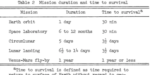
required useful load becomes much greater. Conversely, as illustrated by the requirements of Table 2, there also is a greater necessity to have more reliable systems and more redundancy in the spacecraft because of the longer return time to Earth. In the Earth-orbital mission as listed in Table 2, return to Earth can be accomplished in less than 30 min,
whereas for the lunar missions it may require 3 i days to return to Earth. All key systems including life support and entry systems must remain operative over this total 3"E"~äay period if the mission is aborted after injection. For the Mars and Venus missions, of course, it is impossible to return until the one-year flight period has passed, Thus, it is
necessary to provide sufficient redundancy or in-flight repair capability to give the crew a high probability of mission success. These requirements compound the designers problem in combating the weight restrictions for advanced missions.
TYPICAL SPACECRAFT SYSTEMS
Before discussing the effects of mission success and crew survival requirements upon the design of the system, it is desirable to describe the several spacecraft configurations and systems that may be considered for these missions.
Fig. 6 shows typical configurations for Earth-orbital and lunar-landing missions. On the right is the Mercury capsule with its small size and minimal volume for a one-man crew.
Next there is a rotating space laboratory^ that was designed for a six-month to one-year life with a 21-man crew and a 60,000-ft3 volume. It rotates to provide an artificial gravity of 0.1 to 0.5 g. This space laboratory uses a solar cell power supply and modular construction with individual life support and electrical power systems in each module for redun- dancy. In event one module fails, it can be isolated and repaired while not affecting the performance of the other sections of the spacecraft. This space laboratory is placed in permanent orbit and has a shuttle vehicle that docks at the nonrotating hub. The shuttle, which might be any one of the entry vehicles currently under development, would rotate the crew periodically (six-week tours were proposed) and would supply spare parts for repair.
On the left in Fig. 6 is a lunar-landing configuration that
2Berglund, R. and Weber, A.E., "Self-erecting manned space laboratory," Inst. Aerospace Sei. (April 30, 1962.)
Ν. J . RYKER JR.
has the external shape of the Apollo spacecraft and a single- stage lunar-landing module. It consists of the crew capsule that provides all of the crew quarters during the mission> a propulsion module that provides the lunar take-off propulsion, and a lunar-landing module. This lunar take-off propulsion system might be considered comparable to, but of greater com- plexity than, the retro-package on the Mercury which is used to provide a retro velocity to deorbit the Mercury capsule for entering Earth's atmosphere.
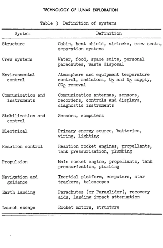
The typical systems that are required for a spacecraft are shown in Table 3· Not all of the listed systems will be required in the spacecraft for each mission. For example, a short duration, Earth-orbital flight does not require a navi- gation and guidance system since the spacecraft is placed into orbit by a boost system that contains the boost guidance and, once in orbit, requires only an attitude control system.
In the Earth-landing system, only the parachutes or a paraglider-type recovery system have been listed. The
Dynasoar-type winged reentry and landing will not be discussed in this paper; however, modified lifting shapes to develop L / D ' S of about 2 may be required for entry from the Mars and Venus missions for a reasonable width of the entry corridor.
MISSION SUCCESS AND CREW SURVIVAL
In addition to the environmental and performance constraints discussed in the previous section, the design of the space- craft is greatly affected by mission success and crew survival requirements. Consideration of these factors is as important as any other factor in the selection of individual system components. In a space mission, crew survival requires at least partial operation of a number of the systems presented in Table 3.
Fig. 7 illustrates probable mission success for two missions, lunar landing and Earth orbit. The wide bar shows schemat- ically a successfully completed mission assuming that the requirement is 900 successful missions out of 1000 launches.
The center line illustrates the aborted missions. The number of aborts permitted during each stage of the mission is shown on the lines connecting the normal flight to the emergency landing. In generating this chart, it was assumed that the lunar-landing mission was successful if a lunar landing was achieved and the crew returned safely to Earth, even if under emergency modes of operation. Thus, aborts do not occur after a successful lunar landing. However, as illustrated in Fig. 7, aborts are possible up to the point of lunar touchdown, and
TECHNOLOGY OF LUNAR EXPLORATION
these have been included in the apportionment. For both missions, it was assumed that the reliability of each stage of the Earth boost system was equal; thus, there were only 33 aborts in 1000 flights for Earth-orbital mission in contrast to ^9 for the lunar-landing mission.
To provide an overall mission success of 0.90 for the lunar- landing mission, a total of only 50 aborts is permissible for the remainder of the phases through lunar landing, that is, for the midcourse correction (which is performed by the lunar- landing module), for the injection into a lunar circular orbit, for deorbiting from the lunar orbit, and for actually accom- plishing the lunar landing. This portion of the mission
includes four separate propulsive phases achieved by re-
ignitions of the lunar-landing module main propulsion system, and a mission duration of almost three days.
To achieve a very high probability of crew survival, that is, no more than one or two losses of the crew out of the total 1000 launches, requires that sufficient reliability and re- dundancy be built into the spacecraft so that it is virtually 100$ reliable for the lunar launch and return mission. This, then,becomes the greatest challenge in the design of the lunar spacecraft. On the translunar flight, failures could be per- mitted in the propulsion system or the environmental control which would cause the crew to abort; however, in this event, alternate modes of operation or redundant systems are required which permit the crew to sustain life for 3è <lays while
returning and re-entering the atmosphere. In contrast, in the Earth orbital missions only 30 min are required to return the
crew to Earth. In an emergency, such as the depletion of the oxygen, electrical power, or reaction control propellant supply, an emergency entry could be made to Earth as long as a secondary supply of 30-min duration was available.
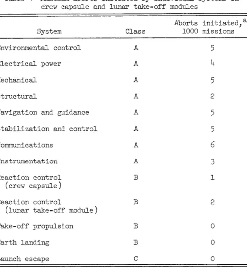
Apportioning the allowable aborts per mission phase does not provide the individual system designer with the data needed to design his system. He requires a measure of the failures per- mitted in his system for the total flight. This was done
representatively for systems in the crew capsule and lunar take-off module (Table 4 ) . The systems listed are of three types: those used throughout the mission, at least inter- mittently, Class A; those not activated until late in the mission, Class B; and the one that is not used except in event Of an abort, Class C.
The Class A systems, which are used early in flight, are apt to cause an abort at any phase. The Class Β systems generally will not cause an abort because they will not be activated
Ν . J . RYKER JR.
until after lunar landing. The only reason for an abort would be the sensing of such things as a gradual drop in the pres-
surizing system for the reaction control system.
The designer1s task, then, is to provide a system that will not initiate aborts in excess of those apportioned and one that has an alternate mode of operation available which will permit the crew to make the 3|"-cLay emergency return to Earth.
SPACECRAFT DESIGN
The four types of constraints which were discussed in the previous sections (the space environment, especially the un- known; the performance limitations, which become severe for lunar and planetary missions; and the mission success and survival considerations) vary greatly for different missions and become more and more critical as the mission objectives extend farther from Earth. Now several specific examples will be considered to illustrate how these affect spacecraft design.
Configuration
First, the effect of the zero-g and the meteoroid environ- ment on the configurations for the space laboratory and the lunar-landing missions will be considered; then the effect of the mission complexity and time to survival will be considered for the same missions. As previously discussed, the lunar- landing mission subjects man to a zero-g environment for less than three days each way. Thus, it is generally considered unnecessary to provide an artificial gravity. For the long duration space laboratory, artificial gravity appears more desirable. Consequently, rather extensive studies were made
(see footnote 2) to optimize the angular rotation, 3 rpm; the radius, 75 ft; and the diameter of the tubular modules (Fig. 6).
The resulting configuration had an extremely large volume (60,000 ft3) and surface area. Because the large area coupled with the long life would result in a high probability of a meteoroid puncture, the configuration used a multiple wall con-
struction with foam separators as a bumper to provide the necessary protection. The weight penalty could be tolerated because the booster (Saturn C-5) has the ability to put a large load into Earth orbit. The compact lunar-landing con- figuration has less surface area, which decreases the proba- bility of a penetration, and is more weight critical. (The launch weight to useful load ratio is as much as 20 times that for Earth orbit as shown in Fig. 5 · ) Thus, although multiwall construction may be employed, the designer must carefully weigh the weight penalties to provide assurance of no pene- tration vs the uncertainties in the meteoroid flux. With the
TECHNOLOGY OF LUNAR EXPLORATION
present uncertainty in flux, he may decide not to add unneces- sary weight but to take a calculated risk on meteoroid
penetration.
The volume provided in the spacecraft is affected by the performance considerations, the mission duration, and the time to survival. First, consider a Mercury type mission of one- day duration. In this case, the single crew member requires only enough volume for him to remain in a seat (less than 25 f t 3 ) . He can perform all operations from his seat, and if an emergency occurs in his normal system he can return to Earth in less than \ hr.
For the space laboratory, a large volume resulted from the provision for artificial gravity. There is a total volume of 3OOO ft3/man. It was feasible to divide the space laboratory into six modules, each with its own solar cell power supply and environmental control system. In event of a failure in one module, the affected module could be sealed, and the rest of the space station would operate satisfactorily. The crew could don space suits and enter the malfunctioned module for repair with onboard supplies or with parts transported by the next shuttle from Earth. In this study, the equipment was mounted inside the spacecraft to facilitate repair and was highly redundant. This approach results in minimizing the number of aborts once the spacecraft is in orbit (Fig. 7 ) ·
Now consider the problem of providing the same probability of success for the lunar-landing mission in view of the increased complexity, Fig. 7; the more severe reliability requirements, Table h; and the greater sensitivity to weight, Fig. 5· To minimize the volume of the entry capsule and consequently the weight of entry heat shield, two approaches could be used. All equipment, except that actually required for entry, could be located in the lunar take-off module, and the crew volume could be reduced to a minimum. Fig. 8 shows the effect of usable crew volume on crew capsule weight for one typical blunt reentry shape. The absolute magnitude of this curve varies directly with the equipment weight on board, but the slope is only a minor function of equipment weight. The range of crew volume which appears practical varies from about 50 ft3/man to 150 ft3 for commodious quarters. This would increase the cap- sule weight by 20$. A reduction in equipment volume by 10Q ft3 would reduce the weight by 550 lb. Thus, it would appear that reduction of both crew and equipment volume would be desirable if mission success and crew survival factors are not considered.
External location of equipment would make in-flight repair infeasible. As illustrated in Fig. 7 and Table i , the mission success requirements would be difficult to achieve and could
Ν . J . RYKER JR.
be accomplished only by added redundancy with its attendant weight increases. The best compromise for lunar-type missions then appears to be to provide the minimum volume consistent with crew performance for long missions and to provide them with direct access for in-flight maintenance and repair of critical equipment. Analytical studies to optimize redundancy and in-flight maintenance have proven extremely difficult because accurate reliability assessment of systems still in the design layout stage is difficult, as is quantitative evaluation of m a n1s ability for emergency in-flight repairs.
Environmental Control System
The environmental control system illustrates both the effect of the mission environment upon selection of systems and con- sideration of the weight limitations and the minimum time for safe return to Earth. Table 5 presents some of the design requirements for the environmental control equipment in the crew capsule. The key subsystems are shown in Table 6, along with candidate techniques for each. The thermal control sub-
system is one that is greatly affected by the mission. Con- sider the space laboratory that passes into Earth*s shadow for half of each 90-min orbit and the lunar-landing mission that will usually be in full sun in translunar and transearth flight but may be in either lunar subsolar or lunar night conditions after landing.
For spaceflight, a typical long duration thermal control system would use fixed radiators to dispose of waste heat. By control of the absorptivity-emissivity ratio, the coolant return could be well below the cabin requirement of 70° F, and radiator area can be quite small. However, on the lunar sur- face during subsolar conditions, the radiator would be absorbing heat from the lunar surface, and cabin temperature would rise excessively. Trade-off studies have shown that the lightest method for the lunar-landing mission is to double the radiator areas, deploy them to a horizontal position, and supplement them when necessary with water boil off. This both compromises the spacecraft and reduces reliability. For fail safety, the deployed radiators would be designed for manual closure in an emergency, because the spacecraft would be short-lived with a malfunctioned radiator system.
Because the radiators are a flight safety item and must
function for safe return, the designer is faced with a decision on the degree of redundancy and margins of safety he must pro- vide. In-flight repair is not feasible (as it might be for cabin fans) because of the external location and because of the nature of the failures (leaks due to meteoroid puncture, for
TECHNOLOGY OF LUNAR EXPLORATION
example). Single redundancy would require an abort when one radiator system was lost. Double redundancy, providing each of the remaining radiators could carry the emergency heat loads, would enable the spacecraft commander to continue the mission with one radiator system out, but would increase the weight
significantly. Thus, comprehensive weight-reliability trade- offs are necessary to make a final decision.
The gas storage subsystem is one example in which (for lunar missions) a more sophisticated system is selected to reduce the
system weight. The simplest method is to store O2 and N2 in high-pressure bottles. This is acceptable for short duration Earth-orbit missions because the total weight involved is
small and the sensitivity to weight is slight. For lunar missions where the total weight of gas is greater, the advan- tage of the cryogenic storage may become overpowering, as shown in Fig. 9· Thus, the engineer is faced with designing the cryogenic system to be more reliable than that of the high- pressure gaseous storage for Earth orbit. This requires time, funding, ingenuity, and probably redundancy, which will
partially offset the weight advantage.
Electric Power System
Along with the environmental control system, the electric power system is one of the most vital systems for crew survival or mission success. All other systems require elec- trical power for operation. The simplest and most reliable system would be a primary battery system such as was used on Mercury. Unfortunately, it is also heavy for long duration missions where the total energy requirement is great. The natural alternative, then, would be to use a more advanced power supply for normal operation with a battery system to provide emergency power for abort. This is satisfactory where the time to survival is low, as with Earth-orbital missions;
but for lunar or deeper space missions, even this is infeasible.
For example, suppose that the primary power failed at the moon with a 66-hr time to return to earth. If the spacecraft re- quired 1 kw emergency power and batteries were assumed to provide 60 w-hr/lb, the battery weight would be 1100 lb.
The combinations of power and duration which determine the type of power generation are shown in Fig. 10, and Table 7 presents the typical systems for the three types of missions.
Earth-orbit missions of short duration can use batteries with little, if any, penalty for both primary and energizing power.
The lunar-landing mission, however, can most efficiently be performed with fuel cells. Batteries could not be considered for relatively long duration missions because of their weight.
Ν. J . RYKER JR.
Solar cells could not be considered because multiple energy sources would be required if the spacecraft landed during lunar night. The fuel cell appears to be the only present alterna- tive, but it is not simple, nor is it developed. Because it must supply emergency power, the system requires at least one redundant fuel cell. One may even consider providing three or four fuel cells operating in parallel. The same philosophy may be applied to the inverters, busses, batteries, and other flight safety items. One readily appreciates the perils of following this path because of the necessity of using compo- nents that do not have a long development history.
The same approach is not necessary in the space laboratory mission for two reasons. A solar cell system is feasible in this environment, and the short time to survival and resupply allows the laboratory to function on batteries for emergencies.
CONCLUSIONS
This paper identified the four major factors that establish the design criteria and, consequently, the design of space- craft for particular missions. Examination of these factors indicated the uniqueness of each mission and the difficulties of designing "universal" spacecraft.
The four factors identified were as follows: l) the natural space and the entry environments; 2) the performance require- ments; 3) "the number and complexity of operational phases; and h) the time to survival.
The first and third factors define the functions required of the spacecraft. The second determines the degree of sophis- tication and advances in the state of the art required to accomplish the mission within the boost system limitations.
The fourth factor, time to survival, which is the most un- familiar to the aeronautical engineer, may be paramount in the design decisions for a mission such as lunar landing. As was illustrated, it affects the configuration, the selection of systems, and the degree of redundancy provided in each system.
Experience has shown that this factor is recognized by the individual engineers who have a tendency to be overcautious in the system design because it is new. The resulting complex- ities and weight may compromise the spacecraft. The intro- duction of this factor tends to increase the schedule and cost of the program because each design decision must be reviewed and substantiated in regard to survival time. This factor does not lend itself to direct analytical solutions, as does performance, and the evaluation studies tend to be lengthy and involved.
T E C H N O L O G Y O F LUNAR EXPLORATION
As more detailed design experience is gained with deeper space missions, the time to survival will be considered more routine, and design concepts and techniques will be evolved for consideration of this factor. It will remain, however, as one that will materially affect the schedule and cost for deep space missions.
Table 1 Environmental consideration (natural environment)
Earth Space Lunar Deep
orbit lab Cislunar landing space Pressure,
ι . γ χ ί ο "
1 0ι . γ χ ί ο "
1 01 . 7 x l 0 "
1 01 . 7 x l 0 "
1 01 . 7 x l 0 "
1 0psi
Meteoroids Whipple Whipple Modified Modified Whipple Whipple
Energetic cosmic cosmic Van Allen Van Allen Van Allen
particle solar solar solar
cosmic cosmic cosmic Surface
properties
Composition Dust &
rock froth Bearing
pressure,
12
to220
psi
Slopes
3
to5
for landing, deg
Tempera-
+250,
tures, °F
-260
Gravity field
space zero-g zero-g zero-g zero-g, zero-g surface
ft/sec0 d
Entry
25,500 25,500 36,000 36,000 50,000
velocity,
36,000 50,000
fps
Ν . J . RYKER JR.
Table 2 Mission duration and time to survival Mission Duration Time to survival8.
Earth orbit Space laboratory Circumlunar Lunar landing Venus-Mars fly-by
1
day6 to 12 months 5 days
6-§- to Ik days 1 year
30
min30
min 31 days 3·| days1 year or less
aTime to survival is defined as time required to return to surface of Earth -without regard to geo- graphic location of Earth landing point.
TECHNOLOGY OF LUNAR EXPLORATION
Table 3 Definition of systems
System Definition
Structure
Crew systems
Environmental control
Communication and instruments
Stabilization and control
Cabin, heat shield, airlocks, crew seats, separation systems
Water, food, space suits, personal parachutes, waste disposal
Atmosphere and equipment temperature control, radiators, O2 and N2 supply, CO2 removal
Communication antennas, sensors, recorders, controls and displays, diagnostic instruments
Sensors, computers
Electrical
Reaction control
Propulsion
Navigation and guidance Earth landing
Primary energy source, batteries, wiring, lighting
Reaction rocket engines, propellants, tank pressurization, plumbing
Main rocket engine, propellants, tank pressurization, plumbing
Inertial platform, computers, star trackers, telescopes
Parachutes (or Paraglider), recovery aids, landing impact attenuation Launch escape Rocket motors, structure
Ν . J . RYKER JR.
Table h Maximum aborts initiated by individual systems in crew capsule and lunar take-off modules
System Class
Aborts
1000
initiated,a
missions
Environmental control A
5
Electrical power A h
Mechanical A
5
Structural A
2
Navigation and guidance A
5
Stabilization and control A
5
Communications A
6
Instrumentation A
3
Reaction control (crew capsule)
Β
1
Reaction control
(lunar take-off module)
Β
2
Take-off propulsion Β
0
Earth landing Β
0
Launch escape C
0
aValues do not include 12 lunar landing module aborts.
TECHNOLOGY OF LUNAR EXPLORATION
Table 5 Typical design requirements for an environmental control system
Item Requirement
Cabin interior Cabin pressure Cabin temperature O2 partial pressure CO2 partial pressure
Relative humidity
Crew metabolic requirements O2
CO2 output
Water consumption Heat output
Equipment
Normal equipment Sensitive components Maximum total heat load
7.0
± Ο.25 psi75 ± 5°
F160
mm Hg min7.6
mm Hg max^0
to70$
1.8 lb/man-day
3 lb/man-day 6 lb/man-day 11,300 Btu/man-day
100 to I5O
0F 50 ± 2°
F8OOO to
12,000
Btu/hrΝ. J. RYKER JR.
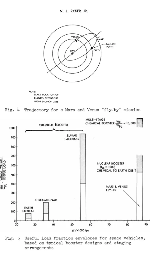
Table β Environmental control system Candidate approaches
Subsystem Earth orbit Space laboratory Lunar landing Oxygen and
nitrogen storage C 02 removal
Thermal control
Pressure
Gaseous or cryogenic
Disposable
Water cooled
Cabin at 5 p s i( 02) , or suit at 3-5 p s i( 02)
Cryogenic or gaseous
Disposable or regenerative Radiator
Cabin at 7 to 15 psia ( O 2 / N 2 ) , or suit at 3.5 p s i a( 0 2 )
Cryogenic or gaseous
Disposable or regenerative Déployable radiator plus water cooling Radiator plus heat pump plus water cooling Cabin at 7 psia
( 02/ N2) , or suit at 5*0 p s i a( 02/ N2) Cabin at 5 psia ( 02) , or suit at 5 psia ( 02)
Table 7 Typical electrical power sources Power source
Mission Primary Emergency
Earth orbital (l day) Space laboratory Lunar landing
Battery Solar cell Fuel cell
(in space) Battery
(during entry)
Battery Battery Fuel cell
(in space) Battery
(during entry)
Fig. 1 Two-week Earth orbital mission trajectories for a manned spacecraft TECHNOLOGY OF LUNAR EXPLORATION
Fig. 2 Typical trajectories for a circumlunar mission N. J. RYKER JR.
TECHNOLOGY OF LUNAR EXPLORATION
Fig. 3 Typical trajectories for a lunar landing mission using the direct landing approach. This is "based upon a single stage for lunar landing and takeoff and a lunar stay of one day
Ν. J . RYKER JR.
L A U N CH P O I N T
N O T E :
E X A CT L O C A T I ON O F P L A N E TS D E P E N D E NT U P O N L A U N CH DATE
Fig. k Trajectory for a Mars and Venus "fly-by" mission
ο !
o l ο -
ΞΐΞ 1000
900 800 700 600
500 _j 400
300 200 100
20
CHEMICAL JOOSTER Λ
MULTI-STAGE CHEMICAL BOOSTER
CIRCUMLUNAR EARTH
ORBITAL
LUNAR LANDING
f r '0-00 0 Π
NUCLEAR BOOSTER
( l sp = 1000)
CHEMICAL TO EARTH ORBIT
MARS & VENUS FLY-BY -
Ν
30 40 50
Δ V-1000 fps
60 70 80 90
Fig. 5 Useful load fraction envelopes for space vehicles, based on typical booster designs and staging arrangements
TECHNOLOGY OF LUNAR EXPLORATION
^ C R E W E N T R Y C A P S U L E
R E T R O P R O P U L S I O N M O D U L E . ~ S P A C E L A B O R A T O R Y
C A P S U L E L O N G D U R A T I O N S P A C E L A B O R A T O R Y ~~j ^ ^ ^ ^
T A K E - O F F K ^ / m
L U N A R 141 m
§ L A N D I N G / / / X m
1 M O D U L E / J[ m
æ^^^\^^20
F T —— ^ ^ ^ ^ f i " " ) P R Q P U L S I Q N^ ^ ^ ^ ^ W ^ ^1 1^ ^ L U N A R L A N D I N G M I S S I O N S H O R l ' D U R A T I O N ^ E A R T H O R B I TFig. β Typical spacecraft configuration for Earth orbital and lunar landing flight
LUNAR « PROPULSIVE PHASES LUNAR 1 / LAUNCH OPΙRATIONS / /-LUNAR BOOST C=3 NON- PROPULSIVE LUNAR LANDING Ι
\ il
LUNAR PHASES 1 I "5/ PARKING DEORBIT-V Wmij^ N^y ORBIT LUNAR ΝY ^H^^^T
9^
LUNAR^^^. X. ELLIPTICAL X. / \ 1 PARKING X ORBIT y S \ ORBIT X \ / ",0^\ \ \ ^TRANSEARTH / / _X ^^L' INJECTION LUNAR ÐÌ TRANSEARTH \Λ CIRCULΔ7\TX^ INJECTION Γ \ pi \ EARTH ORBITAL ç läm OPERATIONS / CORRECTION χ ' / Λ COURSE / CORRECTION / / Y \ \ — / CORRECTION — / / \ \ TRANSLUNAR—ν / ORBIT ^ ^X ENTRY INJECTION \ R INJECTION < ENTRY EARTH \ Π ^ PARKING ORBITMI^ ^ ^-ENTRY 17^ Ρ Ι «Κ Τ CTATC WE — 1ST STAGE GJ S ^\ — 17^\ SEPARATION |Τ X EARTH El > EMERGENCY EARTH H l^NDING^ EARTH \ / LAUNCH Β ι 'LANDING \J LANDING M ' r lanugo LANDING\/ 1000 99 900 1000 34 966 LAUNCHED ABORTED SUCCESSFUL LAUNCHED ABORTED SUCCESSFUL MISSIONS MISSIONS MISSIONS MISSIONS LUNAR LANDING MISSION EARTH ORBITAL MISSION Fig. 7 Comparison of space vehicle reliability and survival requirements for lunar landing and earth orbital missions based on equal reliabilities for the first two booster stages N. J. RYKER JR.TECHNOLOGY OF LUNAR EXPLORATION
9000 «
_ 8000 h
<
7000
6000
5000 I —I
300
J
100 200 300 400 500 600 USABLE CREW VOLUME (FT3)
Fig. 8 The effect of usable crew volume on the crew capsule gross weight, including the effects of entry weight on the heat protection system
G A S E O U S S T O R A G E
C R Y O G E N I C S T O R A G E
20 40 60 M I S S I O N D U R A T I O N M A N DAYS
G A S E O U S S T O R A G E
C R Y O G E N I C S T O R A G E
0 20 40 M I S S I O N D U R A T I O N M A N DAYS
Fig. 9 The effect of mission duration on oxygen and nitrogen systems weights for gaseous and supercritical storage methods
Ν. J. RYKER JR.
10,000
1,000
- 100
10
1.0
0.1
0.01
-CHEMICAL DYNAMIC
CRYOGENIC HYDROGEN AND OXYGEN EXPANSION ENGINES
BATTERIES
NUCLEAR FISSION
SPACE LABORATORY
LUNAR LANDING
NUCLEAR FISSION , L ^AND^SOLAR FURNACES I
\ SOLAR CELLS AND I SOLAR FURNACES
SOLAR CELLS AND RADIOISOTOPES
MIN 5 MIN
1 HR
1 DAY DURATION (TIME)
1 WK
1 MO
1 YR
10 YR
Fig. 10 Recommended types of space power systems to provide minimum spacecraft weight