R. H. Shaw* and R. A. Thompson/
Pratt & Whitney Aircraft Division, United Aircraft Corporation, East Hartford, Conn.
Abstract
The purpose of this paper is to show how such cells are integrated into an optimum powerplant for a space mission; it will include a discussion of cell performance parameters. Be- cause of its advanced state of development at Pratt & Whitney Aircraft, only the Hydrox/ cell will be considered here. The Hydrox cell employs hydrogen and oxygen reactants, dual poro-
sity nickel - nickel oxide electrodes, and aqueous potassium hydroxide electrolyte. The use of metallic electrodes permits operating temperatures in the range of kOO to 500°F. These temperature levels result in the high power densities neces- sary for low powerplant weight and in heat rejection tempera- tures compatible with earth and lunar thermal environments.
Introduction
A fuel cell is a device for the direct conversion of chemical energy into electricity. Two reactants, a fuel and an oxidi- zer, are supplied to the cell to be consumed in an electro- chemical reaction for the production of electricity. Thermal efficiencies of over 70$ are feasible with fuel cell power- plant s.
As the scope of space operations increases towards extensive earth-orbiting and lunar missions, the hydrogen-oxygen fuel cell, by virtue of its high thermal efficiency and water pro- duction, becomes the most practical means of electrical power
Presented at the ARS Space Power Systems Conference, Santa Monica, Calif., September 25-28, I962.
^Project Engineer.
/Assistant Project Engineer.
-^Registered trademark of the Leesona Corporation.
generation. Most of the technical literature to date has dealt with the electrochemical phenomena of a single fuel cell.
Cell Concept and Performance Cell Concept
The heart of any fuel cell powerplant is the cell itself.
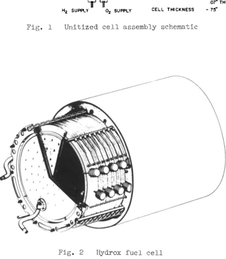
One Pratt & Whitney Aircraft concept is shown schematically in Fig. 1. A disc-shaped cell results in the most compact configuration. Several features of the cell are apparent.
1) Between the dual porosity nickel electrodes is the electrolyte whose expansion and contraction is contained at essentially constant pressure by an expansion device shown schematically as a bellows in the Fig. 1. The use of a dual porosity electrode permits nominal changes in reactants- electrolyte pressure differences without substantially chang- ing the location of the reaction site.
2) A seal to contain the electrolyte between the electrodes must be also an electrical insulator. Shown schematically is a seal which may typically be made from teflon.
3) A perforated nickel backup plate is used to support the oxygen electrode sinter structure. The hydrogen electrode
sinter is self-supporting.
k) A heater is incorporated to provide startup heat require- ments and, for very low power operation, to provide makeup heat to the cell.
5) Cell assemblies are stacked one against the other so that the electrical contact areas are mated with additional cells to build a module assembly. Because the hydrogen, oxygen, and exhaust vent to common manifolds, the cell supply lines must be insulated electrically from the manifolds.
Cell Performance
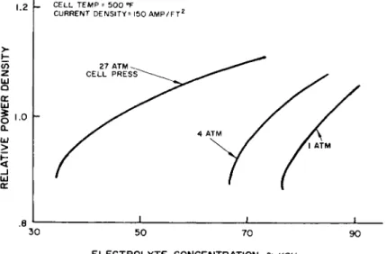
Fig. 3 shows how the net voltage of each cell varies with power density. It can be shown that the thermal efficiency of the cell is proportional to the voltage and is close to 90$> at low power densities. As power density is increased, an ideal cell would remain at constant voltage. The drop in voltage is indicative of increasing losses and decreasing thermal efficiency. Progress toward high efficiency at high power is illustrated in Fig. 3. This progress results from electrode structure development. These data are for a cell
temperature of 500°F, a pressure level of 15 psia, and an electrolyte concentration of 85$ KOH. Cell performance is influenced by temperature, pressure, and electrolyte concentra- tion and is discussed below.
The relative power density for a given load varies with cell temperature as shown in Fig. k. The data are for a cell at a pressure of about 15 psia with an -electrolyte concentra- tion of 85^ KOH throughout the range of cell temperatures.
At a given current density the power density decreases with temperature. This effect is less pronounced at low current densities, which suggests that the operating temperature may be low at low powers. It is clear that the best operating temperature at high current densities is at least 500°F and probably higher. Limitations of seal design and materials currently prohibit operation at higher temperatures.
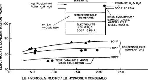
The effects of pressure and electrolyte concentration on the power density of the cell will now be examined. The perfor- mance variation with electrolyte concentration and cell pres- sure for a cell operating at 500°F and I50 amp ft^ is indica- ted in Fig. 5. At any given concentration there is a perfor- mance increase with increasing pressure. In general it has been found that the powerplant weight-to-power ratio is minimum at a pressure level of about k atm.
Typical Fuel Cell Powerplant
To integrate properly an assembly of cells into a power- plant it is necessary to examine in some detail the require- ments for removal of water and waste heat. Although these are accomplished simultaneously, it is convenient to discuss the requirements separately.
Water Generation
Water is generated within the hydrogen electrode in the vicinity of the interface between the fine pore and the coarse pore structure of the sinter as shown in Fig. 6. At this interface the reaction is considered to be monatomic hydrogen plus a hydroxyl ion producing water, electrons, and heat.
Since water is produced on the hydrogen side of the cell, hydrogen is used to absorb the water for removal. Excess hydrogen passes through the cell picking up heat and water, and some is absorbed within the electrode structure to provide the reaction. The water will be in the form of vapor.
Water Removal Requirements
Removal of water from the powerplant eventually must be accomplished by condensation of the water vapor-hydrogen mixture. The requirements for the absorption of water by the hydrogen and the influence of these requirements on the condensing temperature will now be examined.
Water produced in this manner has been found fully to meet standards for potable water and to have a pH of approximately 6.7 and no bacteria. Circulation of excess hydrogen to re- move the reaction water from the cell requires that the sum of the water into the cell plus that produced is equal to the water in the exhaust. Any two of these quantities must be chosen in a particular manner to insure the proper mass balance within the cells. To establish the relationship, an analytical model of the phenomena was adopted.
The model shown in Fig. 7 is essentially a pot of electro- lyte with a semipermeable membrane (electrode) separating the electrolyte from the hydrogen. Using analytical techniques and the assumption that the hydrogen and water are in thermal and mass equilibrium with the water in the electrolyte at the exit from the cell, a relationship is found between the elec- trolyte concentration, the specific humidity of the inlet hydrogen, and the ratio of the hydrogen recirculated to the hydrogen consumed. Since the specific humidity of the in- coming stream establishes the temperature at the end of con- densation, the lines on Fig. 7 may be plotted.
It should be noted that it may be desirable to operate with a constant electrolyte volume. For a fixed cell tempera- ture this is equivalent to a constant electrolyte concentra- tion. To attain this it is necessary to operate with a
fixed recirculation ratio and a fixed inlet specific humidity.
The result of these studies is a firm understanding of the mechanism and requirements for removal of water from the cell.
Heat Generation
Heat generation occurs at the reaction sites in both elec- trodes and at the sites where losses occur. At power den- sity outputs of the order of 135 w/ft , the thermal effi- ciency is about 70$>j and the heat to be rejected will be about 30^ of the total energy. Even with cryogenic reactant storage, the heat rejected is too large to use the reactants as a heat sink, and an external sink is required.
Heat Removal Requirements
Heat is removed from the cell by three mechanisms. The first two are radiation and conduction from the module casing;
the third is convection by the recirculated hydrogen. By operating at a fixed cell temperature the radiation and con- duction heat rejection are independent of the power level and may he considered fixed. The remainder of the heat re- jection must be done by hydrogen cooling flow. The necessary amount of this cooling will be dependent on the power level.
Fig. 8 shows the flow and temperature level of the recir- culating hydrogen required for convective heat removal. At low temperatures the flow entering the module can absorb a large amount of heat, thereby minimizing the flow rate. A low limit of temperature is indicated and is determined by the maximum expected sink temperature. As the inlet tempera- ture approaches 500°F the required flow approaches infinity,
since the temperature rise approaches zero. As the power level is varied the temperature of the recirculating flow must also vary. Because the temperatures are generally above that required for condensing the produced water from the exhaust stream, it becomes necessary to devise a system* where- by the condenser can operate at a temperature lower than that allowed for module heat removal.
System Requirements
The system must provide the following functions: supply reactants, condense and remove water external from the cells, absorb water and heat from the cells, and regulate module temperature. The system shown in Fig. 9 has been devised to allow condensation of product water at low temperatures and yet to provide module cooling flow at elevated temperatures.
A regenerator between the module and heat sink exchanges heat between the module exhaust and module inlet flow. It should be emphasized that the regenerator is necessary only for sys- tems having large variations in power level.
The reactants are supplied under pressure to the reactant pressure regulators. These provide the fuel cell with hydro- gen and oxygen at proper pressure to maintain the correct interface between the electrolyte and the reactants within the electrodes. A surplus of hydrogen is recirculated to remove the water formed in the reaction and also to remove the waste heat. This recirculating gas leaves the fuel cell and passes through a regenerator to a condenser radiator, where the waste heat is radiated to space. A major portion of the water vapor carried from the fuel cell is condensed and car- ried by viscous forces to the separator. A separator
utilizing centrifugal forces separates the liquid water from the gas and forces it into a water storage system. The re- circulating hydrogen containing some water vapor is pumped hack to the hydrogen inlet of the fuel cell through the regenerator. If the returning gas temperature is too low, flow can be diverted around the regenerator Ъу a control that senses module temperature.
Environmental Considerations
To insure proper functioning of the complete fuel cell powerplant system throughout any space mission, an analysis must he made of each step in the mission profile from ground test, through launch, earth orbit, to planet or space ren- dezvous, and return. Limiting conditions of temperature, shock, acceleration, and radiation must be considered for each component as it affects the design. Selection of mate- rials, orientation of components, cycle selection, and opera- ting modes must be adjusted to provide inherent compatability with the vehicle and its mission. A typical mission, such as a manned lunar surface exploration, would involve eight distinct environments: l) earth surface, 2) earth launch, 3) earth orbit, k) deep space, 5) lunar orbit, 6) lunar land- ing, 7) lunar surface, and 8) lunar launch.
Studies have shown that the problems associated with Van Allen and particle radiation, mechanical loading, and hard vacuum should be solved with conventional design techniques.
The most severe environment imposed on the powerplant is the extreme range of thermal radiation sink temperatures. The magnitude of this change for a lunar mission is about 600°F.
Studies have shown that a condenser/radiator, as shown in Fig. 9j> of a fixed size is not capable of rejecting heat in a lunar orbit or on the lunar surface without freezing in deep space.
The desire to match the fuel cell powerplant to the ex- tremes of sink temperatures with a fixed heat rejection area requires an intermediate fluid loop between the powerplant and the environment. Furthermore, the fluid loop must be capable of cooling the powerplant exhaust to remove the waste heat and condense the correct amount of water while operating over a range of sink temperatures. One such system is shown schematically in Fig. 10.
A fluid is circulated through the condenser and absorbs heat from the hydrogen-water vapor flow. This flow passes through a regenerator to adjust the fluid temperature in the radiator to the heat sink requirements. From the regen- erator the flow circulates through the radiator, some is passed back through the regenerator, and the remainder by- passes the regenerator. The regenerator and bypass serve to cool the fluid to temperature limits required by the heat rejection characteristics of the radiator and to heat the fluid to the temperature required by the condenser. The amount of bypass is controlled by the condenser temperature.
An accumulator is used to maintain acceptable pressure levels.
An electric motor driven pump is required to circulate the fluid.
Many alternate systems have been evaluated including a water boiling system and a staged hydrogen circulating ra- diator. The forementioned system is desirable because of the following advantages: l) the system satisfies the heat re- jection requirements of the fuel cell; 2) the radiator area is fixed; 3) water boiloff is not required; k) the system will operate in deep space, in a lunar orbit, or on the lunar surface with random orientation; 5) the required fluid temperature levels are compatible with the favored working fluid; and 6) control is simple.
The working fluid should feature: l) temperature stability for long life, 2) compatibility with structural metals for long life, 3) low viscosity and high specific heat for low pumping power, h) high thermal conductivity for minimum radiator area, and 5) low vapor pressure for minimum struc- ture weight. A glycol-water mixture is one fluid that exhibits satisfactory features.
Optimizing the Space Powerplant
Finally, the optimum design of a powerplant of the type discussed here will be considered. Powerplant optimization requires a knowledge of the desired balance among system reliability, weight, performance, and other characteristics of importance to the mission. A full discussion of these items, however, is beyond the scope of this report. Only those optimizations involving the balance between dry weight and reactant weight (performance) to obtain the minimum overall weight will be considered here.
Such optimizations require a knowledge of factors such as maximum and minimum power and voltage levels and mission duration as well as environmental conditions. These factors in turn depend on the mission objectives, where the space- craft is going, how long it will take, how it is getting there, etc. Because of the difficulty in generalizing these factors, typical requirements for a lunar landing mission have been selected. These are shown in Fig. 11.
The primary design parameters that enter into the optimiza- tion are l) cell temperature, 2) cell pressure^) cell current density.
1) Cell temperature: Cell performance gains above 900°F have been shown to be negligible, and operation above 500°F is not required. The effect of temperature on dry weight is negligible in the operating range of 3OO "to 500°F. Conse- quently, minimum powerplant weight will occur at a cell tem- perature of about 5OO°F.
2) Cell pressure: Cell performance also will improve with increases in system pressure level. However, there is a maximum pressure beyond which the overall system weight will increase (increased hardware weight offsetting increases in allowable power density). Minimum system weight and radiator size occur at 60 psia gas pressure. The 60 psia pressure allows operation at high condensing temperatures and hence smaller radiators.
3) Cell current density: Current density is the major variable that determines system weight. For a particular mission a value may be found which will minimize the sum of powerplant and reactants weight at any point in the mission.
Low current densities imply large and hence heavy cells and low reactants consumption. High current densities result in a small module size but relatively high reactants con- sumption.
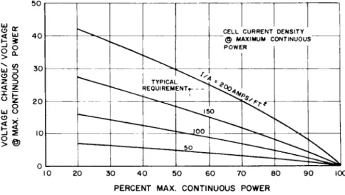
Voltage and overload requirements impose limits on the range of operating current density. This is presented in Fig. 12, 13, and l4 for the particular requirements and
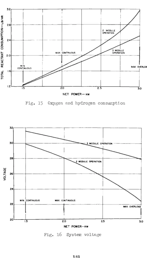
shows the limiting current density as 120 amp/ft2. For this condition the current density at the overload condition is 3OO amp/ft2. Figures 15 and l6 show the reactant con- sumption and system voltage at the various power levels for a system that operates at the 3OO amp/ft2 overload con- dition. The fuel cells provide the proper voltage regulation requirements over the normal load range.
The influence of the foregoing variables on powerplant weight are summed to establish the optimum system weight for particular mission requirements.
Conclusion
A powerplant system has been devised to satisfy the re- quirements of the fuel cells and the thermal environments of a typical lunar mission. The fuel cells are of inter- mediate temperature, dual porosity design for maximum power density and maximum heat rejection temperature. Product water and heat are removed from the cell by recirculated hydrogen flow, and potable water is condensed and separated.
Temperature equilibrium, at low power, is maintained by re- heating the recirculated hydrogen and water vapor with the hydrogen and vapor discharged from the cell. Waste heat is transferred from the recirculated hydrogen flow to a cool- ing circuit that incorporates a regenerator and a control to maintain the correct condensing temperature of the water vapor over the range of in-flight thermal environments. The system delivers electricity and water and must reject heat at about 200°F. In addition to the reactant supply, the system requires electricity for motor-pump units. Ana- lyses of the operating modes have demonstrated the basic capability of the powerplant to perform a lunar mission.
EXHAUST PORT
ELECTRICAL CONTACT AREA SEAL-
ELECTROLYTE
EXPANSION DEVICE
— ELECTRICAL CONTACT AREA COVER PLATE
DUAL POROSITY SINTER BACK-UP PLATE (PERFORATED) HEATER
TYPICAL DIMENSIONS ACTIVE ELECTRODE - Ю" DIA.
07" THK.
CELL THICKNESS - 75"
02 SUPPLY
Fig. 1 Unitized cell assembly schematic
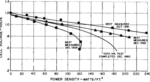
Fig. 2 Hydrox fuel cell
1.4
o i.o ш e>
Ë
o>
u
.8
5 ^ ^
BEST MEASURED
BEST MEASUR OCT. 1 FD
361
^ A BE ME DE
• 1000 HR. TEST ' COMPLETED DEC. I960
ST ASURED C. I960
0 20 4 0 60 80 100 120 140 160 180 200 220 240 POWER DENSITY-WATTS/FT.*
Fig. 3 Experimental cell performance; cell temperature 500°F; cell pressure 15 psia
2.0
l.5h Q or
LU g '■<>
LU >
5
LUor 0.5
350
N0 ELECTRODE ACTIVATION CATALYST
CELL CURRENT DENSITY AMPS/FT2
SAFE OPERATING LIMIT FOR SEALS ft INSULATION
200 175 150 125 100
l J _
400 450 CELL TEMPERATURE-eF
500
Fig. k Cell performance; variation with cell temperature
1.2
Q Ш (E
I i.o
OL Ш
>
Ш tr
.8
CELL TEMP = 500 °F
CURRENT DENSITY= 150 AMP/FT2
27 ATM CELL PRESS
_1_ JL
30 50 70
ELECTROLYTE CONCENTRATION-% KOH
90
F i g . 5 Cell performance
HYDROGEN
WASTE HEAT a WATER
ANODE
INTERFACE (H + OH~= H O + e l
ELECTROLYTE
FINE PORE
EXHAUST
WATER, HYDROGEN, & HEAT
Fig. 6 Heat and water generation
SCHEMATIC X o
I
Ь 100 r
Ш
£ 901 o
Ü
d
8°l-I -o
UJ UJ 7 0 I
RECIRCULATING FLOW H , a H-0
WATER PRODUCTION
SEMI PERMEABLE MEMBRANE ELECTROLYTE
KOH a H20 500F I5PSIA
# TEST DATA(80eF, M0#F) MASS EQUILIBRIUM -
Jv
-EXHAUST н500 F 20PSIA 2а н2о MASS EQUILIBRIUM- EXHAUST GASES, WATER LAYER, a ELECTROLYTECONDENSER EXIT TEMPERATURE
-J_ - L _1_
5.0 10.0 15.0 20.0 LB. HYDROGEN RECIRC/LB. HYDROGEN CONSUMED
25.0
Fig. 7 Cell water removal mechanism
40i ,_ Ta = 475eF
Z
o
3
o 30 h
2 2 0 b
I 0 h
I I I _L
"50 60 70 80 90 100 PERCENT OF MAXIMUM POWER OUTPUT
Fig, 8 Hydrogen circulation required for waste heat removal; cell temperature 500°F; constant hydrogen inlet specific humidity
02 N2 H2
PRESSURE REGULATORS
FUEL CELL MODULE
H2"*" H2 ° »
BY PASS X r r - h
CONDENSER RADIATOR
REGENERATOR
PUMP/SEPARATOR
аг~
, 9 Fuel c e l l powerplant schematic; direct condenser/radiator
OXYGEN SUPPLY PRESSURE REGULATORS.
* ■; &
[TROGEN _ A HYDROGEN
^* SUPPLY
FUEL CELL MODULES
BY-PASS CONTROL
CONDENSER
PRIMARY REGENERATOR
SECONDARY
REGENERATOR
Ш
PUMP, MOTOR , ft SEPARATOR
/
H20 TO STORAGE
PUMP, MOTOR, a ACCUMULATOR
BY-PASS CONTROL
3=
4 SECONDARY COOLANT
SPACE RADIATOR
Fuel cell powerplant schematic; secondary fluid radiator
RELIABILITY: COMPLETION OF A MANNED 14-DAY MISSION THREE INDEPENDENT FUEL CELL MODULES. ANY TWO CAPABLE OF
NORMAL LOAD ANY ONE CAPABLE OF
EMERGENCY LOAD
CONTINUOUS OVERLOAD NET POWER, KILOWATTS
VOLTAGE, VOLTS DC
I 5 M I N — 2 0 M A X 32 MAX — 2 6 MIN
3 0 MAX
LAUNCH EARTH ORBIT TRANS -LUNAR LUNAR ORBIT a
LANDING LUNAR SURFACE LUNAR LAUNCH a
ORBIT TRANS-EARTH EARTH ORBIT
0.4 KW -HRS
MISSION POWER REQUIREMENTS
0 1 2 3
AVERAGE LOAD -KW.
Fig. 11 Typical lunar mission requirements
1.5
OVERLOAD
REQUIREMENT LIMITING .. CURRENT DENSITY,
NO VOLTAGE
REGULATION REQUIRED VOLTAGE CONTROL REQUIRED
WEIGHT WITH VOLTAGE REGULATOR
50 100 150 2 0 0 250 3 0 0 350 CURRENT DENSITY AT MAX. CONTINUOUS P O W E R - A M P S / F T .2
g. 12 Total system weight; typical lunar mission
C!> O 2 3
O O
O >
50
40
30
20
10
* - » * ^ ^ RE0UIREM TYPICAL
CELL P0WE
CURRENT DENSITY AXIMUM C0NTINU0U
R 1
ENT,- - - > < ^4J
" ^ ^ ^ 1 5 0
— inn _ 50
\ T ^ *
s
10 20 30 4 0 50 60 70 80 PERCENT MAX. CONTINUOUS POWER
90 100
Fig. 13 Cell voltage regulation
5.0
& 4.0
P Q.
CO 3 P B 3.0 Ш
Ц
3
5P
< 2 010
\
\
TY RE PltAL _ QUIREMENT
1 4 . 1
50 100 150 200 250 CELL CURRENT DENSITY @ MAX. CONTINUOUS POWER
300
F i g . ll· Overload c a p a b i l i t i e s
| 28|
z o
t
i 24 z oÜ
§ 2.0
CO NT Ml N.
INUOUS
MAX CONTINUOUS
2 MODULE _, OPERATION /
^— Ъ MODULE У^ OPERATION
MAX. OV
ZO 2.5 NET POWER—KW
3.0
Fig. 15 Oxygen and hydrogen consumption
2.0
NET POWER-KW
F i g . l 6 System v o l t a g e