SATURN PROJECT STATUS Ο . H. L a n g e1
NASA Marshall Space Flight Center, Huntsville, A l a . A B S T R A C T
Significant advances were made in the Saturn program from October 1961 to July 1 9 6 2 . T w o Saturn C-l vehicles were suc- cessfully launched. Development of a two-stage C-l vehicle was begun; a two-stage interim vehicle, C-1B, was approved.
A development program was initiated for the advanced Saturn, C-5 configuration. Facilities activation, design planning and construction were begun at the New Orleans Michoud Plant, Mississippi Test Facility, and Cape Canaveral Launch Complex 37, respectively. Hardware development of a Nova vehicle was deferred and additional operational and design studies
initiated.
INTRODUCTION
This article is a report on the development programs of the Saturn heavy carrier vehicles, including major program accom- plishments since October 1961. O n that date, status of the Saturn Program was presented during the "Space Flight Report to the N a t i o n " ARS meeting in New York; briefly, program status, as of O c t o b e r 1961, was as f o l l o w s :
1 ) The mission of the Saturn C-l vehicle had been expanded to include low, earth-orbital flights of prototype Apollo spacecraft.
2 ) To support manned flight, the early three-stage C-l Saturn was being modified to a man-rated, two-stage configu- ration.
3 ) In parallel with C-l development work, studies of ad- vanced Saturn-class vehicles were being continued to support NASA's lunar mission.
Presented at A R S Lunar Missions Meeting, Cleveland, Ohio, July 17-19, 1 9 6 2 .
iDirector, Saturn Systems Office
Ο. Η. LANGE
During the following nine-month period, October 1961 to July 1962, two Saturn vehicles were successfully launched from Cape C a n a v e r a l . Design was completed of the two-stage C-l vehicle with improved, man-rating characteristics. A p - proval was given for the development of interim two-stage vehicle, C-1B. A program for development of an advanced launch vehicle, identified as the C-5, was initiated, with applicable stage and engine development programs begun. The Michoud Plant, near New Orleans, was activated for industrial production of Saturn boosters. Design planning was begun for the Mississippi Test Facility, where Michoud-produced stages will be static tested. Construction of Launch Complex 37 for operational C-l vehicles was begun.
A s the preceding summary indicates, considerable activity was compressed into nine months, and pace of vehicle d e v e l - opment greatly increased. The most spectacular events of the period were flight tests of the Saturn C - l .
SATURN FLIGHT T E S T I N G
The first Saturn flight was made on O c t o b e r 27, 1961. Flight test objectives included verification of the vehicle a e r o - dynamic and structural design, plus test of the propulsion and control system and operational test of the ground support and launch equipment.
Only the booster will be live during the first four R&D launches of the early C-l Saturn vehicle design (the Block I v e h i c l e s ) . Upper stages will be water-ballasted to simulate full propellant loading.
The first test was quite successful. The 10-hour countdown w a s not interrupted by technical h o l d s . Automatic fueling and sequencing processes were satisfactorily carried out.
Performance of ground support equipment and launch equipment was good. Ignition, thrust-buildup, and lift-off, and over- all performance of the booster during flight was very s a t i s - factory. In the final seconds of burning, inboard engine shut- down occurred slightly earlier than anticipated because of propellant rotational slosh. O u t b o a r d cutoff came, as p r e - dicted, 6 sec later. A l l thrust decays were smooth. The v e h i - cle experienced practically no disturbance torques at cutoff.
A s a result of this flight test, more propellant tank baffling was added to reduce slosh during the final seconds of flight.
The modification was successfully tested during the second Saturn flight in April 1 9 6 2 .
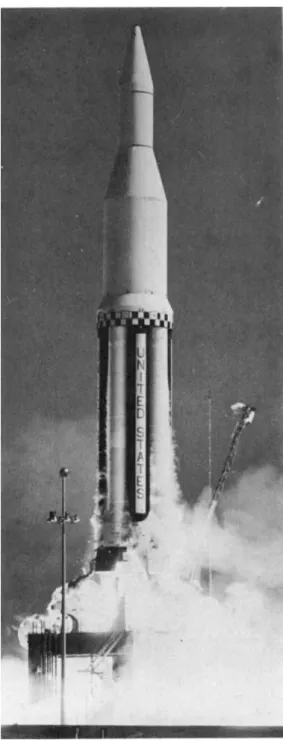
The second Saturn vehicle also was launched without a
technical hold. (See Fig. 1.) Flight objectives duplicated those of the first flight. Project High Water, an experiment in upper-atmospheric physics, was performed at 65 nm altitude.
The vehicle was deliberately destroyed, dumping 100 tons of upper stage water ballast into the ionosphere to observe o p t i -
cal and meterological e f f e c t s . Data from this experiment are still being analyzed.
Vehicle propulsion and control systems performed as expected throughout powered flight. New baffling reduced slosh to within acceptable limits. Inboard and outboard engine cutoff occurred as predicted.
In late May 1962, the third flight booster completed accept- ance testing. Final checkout was begun on June 20, and the vehicle shipped to Cape Canaveral on September 10, for launch in the last quarter of 1962.
Pre-static checkout of the fourth flight booster w a s s a t i s - factorily conducted, and the booster transferred to the static test stand on J u l y 31, 1962. Flight qualification static testing of the booster was successfully concluded on September
26, 1962.
Various secondary missions were planned for the third and fourth Saturn v e h i c l e s . One such mission was an engine-out test to examine tail-heating effects and to confirm operation of the propellant feed system under emergency inflight con- d i t i o n s . The inert second stage of the fourth flight vehicle was modified to simulate the second stage flight configuration.
SATURN C-l, BLOCK II CONFIGURATION
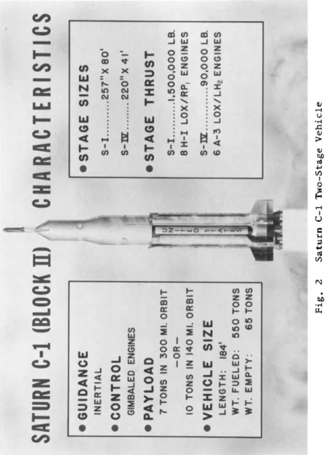
Redesign of the initial three-stage Saturn to a two-stage configuration began in 1961. The first two-stage, Block II vehicle (Fig. 2) will be flown in 1963 with a live second stage. Initial flights will concentrate on booster and second stage performance c h a r a c t e r i s t i c s . Prototype A p o l l o s p a c e - craft will be carried to low-orbit on later f l i g h t s . S a t u r n / Apollo compatibility and interface events will be i n v e s t i - gated. In addition, the Manned Spacecraft Center, Houston, T e x a s , will secure A p o l l o subsystem development information, with particular emphasis on re-entry heat shielding.
S-I STAGE, BLOCK II CONFIGURATION
Block II design changes provide a marked increased in v e h i - cle p e r f o r m a n c e . The booster for the fifth flight vehicle has
Ο. Η. LANGE
a propellant capacity increase from 750,000 to 850,000 lb.
The booster used the improved H-l engine, uprated to 188,000 lb of thrust. The propellant feed system was modified, and all tanks feed from a common manifold, tapped for each engine.
Four detachable fins were added for increased vehicle stabil- ity to augment dynamic control and safety of abort.
Other Block II changes were redesign of the upper stage adapter and replacement of the 48 1-cu-ft nitrogen fuel-pres- surizing spheres with 2 20-cu-ft spheres. Four retrorockets were added to assure positive stage separation. The guidance instrumentation, relocated to a pressurized instrument unit, will transmit guidance and sequencing signals to the appro- priate stages during powered flight.
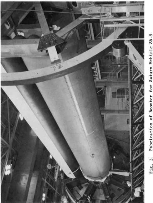
The booster for the fifth flight vehicle is shown in Fig. 3, Marshall Space Flight Center will assemble most of the R&D boosters and will also build certain booster subassemblies.
However, industry is making major contributions in fabrication of the R&D boosters. Contracts have been let for fabrication of fuel and oxygen tanks, the pressurization spheres, the tail fins, and the engines, to cite only major hardware.
S-IV STAGE, BLOCK II CONFIGURATION
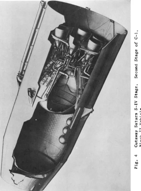
The Saturn second stage, S-IV, (Fig. 4) is under development by the Douglas Aircraft Corporation. In designing a stage to burn liquid hydrogen, a number of severe engineering and de- sign problems have been solved. For example, development of internal fuel-tank insulation and the common bulkhead sepa- rating the propellant tanks. Satisfactory development of the helium heater for theLox -tank pressurization is also
continuing.
Early in 1962, checkout of the S-IV stage electrical systems and related ground support equipment began at the Douglas Systems Integration Area. Later, the GSE will be used to check out the All-Systems (flight-type) S-IV stage
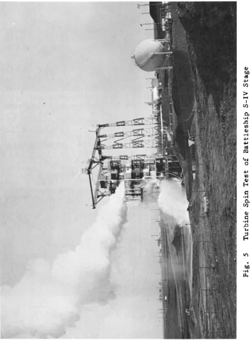
0At the Douglas Sacramento Test Facility, cold-flow testing of the six-engine battleship S-IV was successfully completed on August 9 ο On August 17, approximately 90,000 pounds of thrust were produced when the vehicle was static fired for a planned duration of 10 sec. (See Fig. 5.) All test objec-
tives were met. Additional static testing culminated, on Sep-
tember 24, 1962, with a successful 60-second firing of the
battleship vehicle.
S-IV STAGE E N G I N E DEVELOPMENT
Since O c t o b e r 1961, several major engine milestones were reachedo In November 1961, the RL10A-1 liquid-hydrogen engine successfully completed Preliminary Flight Rating T e s t s at Pratt and W h i t n e y in Florida. In June 1962, PFRT of the RL10A-3 engine was completed successfully. The A - 3 engine, w h i c h powers the S-IV stage, is basically similar in design to
the A - l , but will burn for about twice as long (around 470 s e c ) .
SATURN C-l FACILITIES
A number of Saturn facilities are under construction. For example, construction of the first of two launch pads at Com- plex 37 began in April 1962. The first two-stage Saturn will be launched from this complex, which will have facilities to store and load liquid hydrogen, as well as Lox and RP-1 f u e l . Construction of the complex will be completed by m i d - 1 9 6 3 .
In September 1961, the government-owned Michoud Plant near New O r l e a n s was selected as the site for industrial production of Saturn b o o s t e r s . The 43-acre plant, one of the largest single-floor buildings in the country, is accessible to deep- water transportation, a critical requirement because of the size and weight of the stages to be moved.
Late in 1961, the Chrysler Corporation was selected to build booster stages for the operational C-l v e h i c l e . Plant p r e p a - rations at Michoud began immediately. A preliminary contract was also signed w i t h the Boeing Company, which will build the Advanced Saturn booster at M i c h o u d .
The Michoud-produced boosters will be acceptance-tested at the Mississippi Test Facility, about 35 miles from Michoud.
NASA is acquiring fee and perpetual easement interests in about 140,000 acres for the facility. To support both Michoud and MTF, a computer facility was established at Slidell, Louisiana, about 5 miles southwest of the test site.
A D V A N C E D SATURN V E H I C L E CONFIGURATIONS
Concurrently with development of the Saturn C-l configura- tion, Marshall carried out intensive design studies of vehicles to support the lunar m i s s i o n . A Saturn C-2 configuration, shown in Fig. 6, was first considered as a follow-on to the C - l . The primary difference between the vehicles was that the C-2 had a high-thrust, liquid-hydrogen stage inserted above the booster.
Ο. Η. LANGE
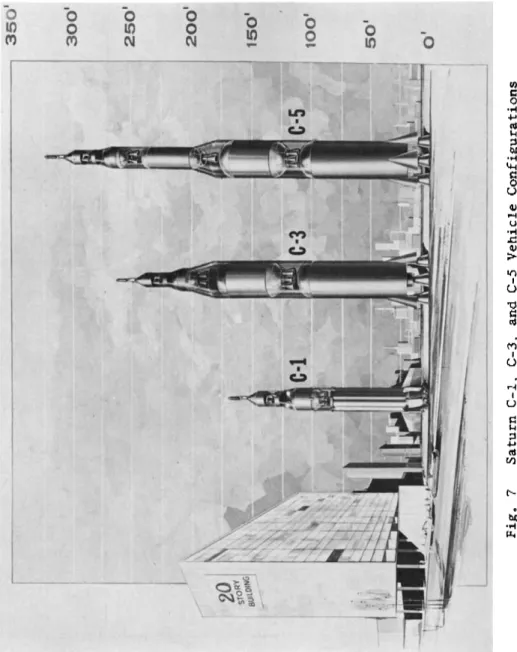
However, during vehicle design studies in m i d-1961, evalu- ation of A p o l l o proposals showed general spacecraft weight increases. T h e s e increases led to bypassing of the C- 2 for a more powerful vehicle, the C- 3 .
The C- 3 , Fig. 7, w a s to be designed for escape missions, including the manned lunar mission via the rendezvous techni- q u e . However, as the manned mission became better defined, payload weights became increasingly severe. Consequently, the C- 3Ts performance grew critically marginal; at the same time, the idea of a multiple rendezvous became less attractive.
A n a l y s i s of vehicle operational capabilities and additional stage optimization studies were continued. Boosters were examined which used four F-l engines (the C- 4 vehicle, not s h o w n ) and five F-l engines (C-5 vehicle, F i g . 7 ) .
Studies showed that a five-engine booster provided a sig- nificant improvement of performance, highly desirable in the event of possible spacecraft weight increases or reduced stage p e r f o r m a n c e . In addition, the fifth engine would allow sub- stantial payload increases when the booster w a s used with nuclear-propelled upper s t a g e s .
SATURN C-5 CONFIGURATION
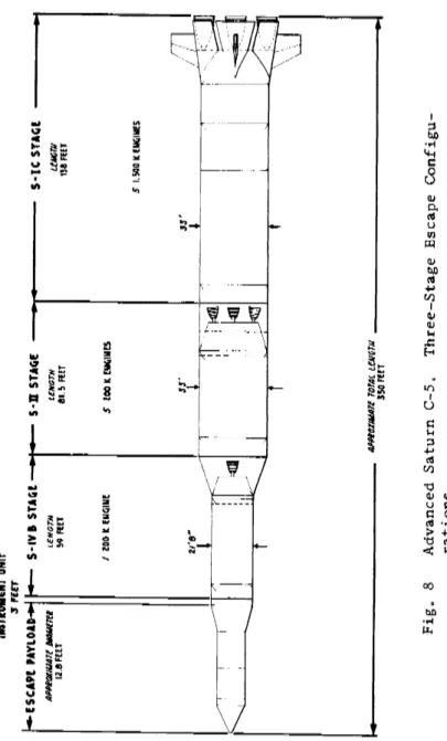
The heavy carrier vehicle, evolving from these studies, is often called the A d v a n c e d Saturn C- 5 . (See F i g . 8 . ) NASA authorized development of the three-stage C-5 in January 1962.
The vehicle is being designed to support manned circumlunar flight and manned lunar landings by the rendezvous technique.
The booster and second stage are optimized to provide a m a x - imum two-stage-to-orbit capability of about 120 tons. By adding the third stage, the vehicle w i l l be capable of escap- ing 45 tons to the vicinity of the moon.
S-IC STAGE, C-5 CONFIGURATION
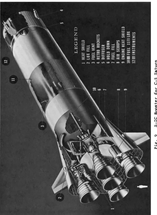
The booster, or S-IC stage for the Advanced Saturn is being developed jointly by Marshall and the Boeing C o m p a n y . T h e stage shown in F i g . 9, will measure 138 ft long and 33 ft in diameter, which will allow horizontal assembly under Michoud's 40-ft ceiling. A small high-bay area will be built for those operations w h i c h must take place in the vertical position.
Five F-l engines will be used, providing a total stage thrust of 7,500,000 lb. Four of the engines, mounted in a square pattern, will gimbal f o r control. O n e F-l engine will
be centrally mounted and rigidly fixed. Static firings of the complete F-l engine assembly began 1962, w i t h the first full-duration, full-thrust static firing conducted in May.
The engine produced slightly over its rated thrust of 1,500,000 lb.
S-II STAGE, C-5 CONFIGURATION
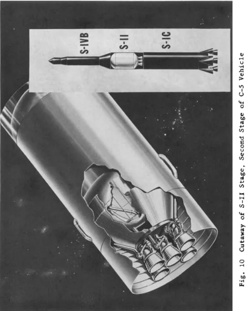
The current configuration of the second or S-II stage is shown in Fig. 1 0 . In November 1961, North American w a s re- quested to redesign the stage from four to five J-2 e n g i n e s . The change provides a total of 1,000,000 lb of thrust and permits a more optimum stage w i t h greater performance and with engine-out capability. The stage is about 82 ft long and 33 ft in diameter. A n insulated common bulkhead sepa- rates the Lox tank and the forward hydrogen tank.
The stage is controlled by gimballing the four outer engines.
The fifth engine is rigidly mounted. Primary guidance and control signals for the S-II (as for all C-5 s t a g e s ) are provided from the vehicle instrumentation unit, located f o r - ward of the third stage.
The J-2 engine for the C-5 second and third stages is being developed by Rocketdyne at Canoga Park and test-fired at the Santa Susana engine development facility. Thrust chamber development has progressed satisfactorily, concurrently with tests of the oxidizer and fuel turbopump assemblies. A number of J-2 engine system tests were conducted, including brief mainstage f i r i n g s . In A p r i l 1962, 9 0 % sea-level thrust was reached during the initial hot-firing tests.
S-IVB STAGE, C-5 CONFIGURATION
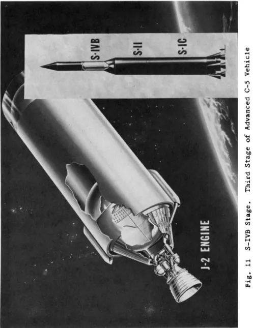
A single J-2 engine is used on the S-IVB stage (Fig. 1 1 ) , the third stage of the A d v a n c e d Saturn. Design studies of the stage have been conducted by the Douglas Aircraft C o r p o r a t i o n . The S-IVB has a diameter of 260 in and a length of about 58 ft.
The stage has a usable propellant capacity of about 230,000 lb. The single engine gimbals for pitch and yaw control.
Auxiliary propulsion systems provide attitude control during coast. Provision for automatic checkout is incorporated in the basic stage design, as it is for the other C-5 s t a g e .
C-1B CONFIGURATION
It is planned to use the S-IVB stage on the C-1B vehicle, the latest member of the Saturn vehicle family. The C-1B,
Ο . Η. L A N G E
w h i c h will be intermediate between the Saturn C-l and C - 5 , was approved for development in July 1962.
The two-stage vehicle, shown in Fig. 12, uses a Block II, C-l booster with an S-IVB upper stage. The vehicle will be capable of placing about 16 tons into earth orbit, and will allow flight test of the S-IVB about one year earlier than previously scheduled. By the mid-1960's it will be possible to flight test the Apollo lunar-orbit configuration in low- earth orbit. These flights will also concentrate on crew training and perfection of module maneuvering in orbit.
LUNAR O R B I T RENDEZVOUS
O t h e r milestones have been passed w h i c h foreshadow a d d i - tional areas of major effort. In July 1962, NASA announced selection of lunar orbital rendezvous as the mode for p e r - forming the lunar landing m i s s i o n . In the present concept of the mission, a single C-5 will be used. The vehicle stands approximately 350 ft high (including the s p a c e c r a f t ) and weighs 6,000,000 lb at launch. A n unmanned lunar logistic vehicle is being investigated to support the lunar explor- ation program.
NOVA
Concurrently, studies are under w a y to establish operational and design parameters of a Nova vehicle. Essentially, the Nova is a follow-on to the A d v a n c e d Saturn program, with a weight-lifting capability of at least two to three times that of the C - 5 . Hardware development of the Nova has been d e - ferred for some time to permit adequate development of p o s t - A p o l l o m i s s i o n s . It will also permit normal, rather than crash program development of the M - 1 engine.
CONCLUSION
M a r s h a l l1s primary program effort is now concentrated on development of the Saturn C-l, C-1B, and C-5 vehicles shown in Fig. 1 3 . T o perform this task w i t h a modest extension of present technology, and within the established mission sched- u l e s , requires not only a major commitment o f program resour- ces, but also a dedicated commitment, by government and in- dustry, to press the program forward in every element. E v e r y - o n e — i n government and industry a l i k e — shares the responsibil- ities, the failures, and the successes as the work advances toward the planned lunar landings and the later missions into deep space.
Fig. 1 Saturn SA-2 Launch from Cape Canaveral, April 1962.
Ο. Η. LANGE
Fig. 2 Saturn C-l Two-Stage Vehicle
Fig. 3 Fabrication of Booster for Saturn Vehicle SA-5
Ο. Η. LANGE
Fig0 4 Cutaway Saturn S-IV Stage. Second Stage of C-l, Block II Vehicle
Fig. 5 Turbine Spin Test of Battleship S-IV Stage
Ο . Η . L A N G E
F i g0 6 Saturn C-l and C-2 Vehicle Configurations
Fig0 7 Saturn C-l, C-3, and C-5 Vehicle Configurations
Fig0 8 Advanced Saturn C-5„ Three-Stage Escape Configu- rations Ο. Η. LANGE
Fige 9 S-IC Booster for C-5 Saturn
Ο. Η. LANGE
Fig. 10 Cutaway of S-II Stage, Second Stage of C-5 Vehicle
Fig. 11 S-IVB Stage. Third Stage of Advanced C-5 Vehicle
Ο . Η . L A N G E
Fig. 12 Saturn C-1B Configuration
Fig. 13 Comparison of Saturn Vehicles