Numerical analysis of biogas combustion in a lean premixed swirl burner
D´aniel F¨uzesi*
Viktor J´ozsa
Department of Energy Engineering, Budapest University of Technology and Economics, Faculty of Mechanical Engineering 1111 Budapest, Muegyetem rkp. 3., Hungary
fuzesidaniel95@gmail.com jozsa@energia.bme.hu
Abstract—Modern combustion technology focuses on lean pre- mixed burners to achieve high thermal efficiency, wide operating range, and low pollutant emissions for steady-state operation. The corresponding applications range from boilers to gas turbines.
The present paper is a preliminary analysis of a turbulent laboratory test burner with 30 kW combustion power by using CFD. The reference fuel was natural gas and four biogases were tested which were modeled as a mixture of CH4, CO2, and H2 in various compositions. Even though the combustion is steady, the steady solution was inappropriate due to the notable presence of unsteady flow structures. Since the combustion in the present case is dominated by volumetric reactions, a coarse boundary layer could be applied near the wall. However, the shear-dominated flow required the use of at least k-ω SST turbulent viscosity model. The transient cases were calculated by using Scale Adaptive Simulation. Among the fuels, natural gas combustion showed flashback due to the bluff body present at the center in the mixing tube inlet. Nevertheless, its extent was low and some central purge air in the real burner will solve this problem. All the flame shapes were V and W, meaning an optimal condition for combustion chamber loading. Even though the overall mass flow rates at the inlet are increasing with the decreasing heating value of the fuel, natural gas combustion showed the highest velocity and temperature in the flow field.
Overall, a small hydrogen dilution of the CH4-CO2 containing fuel acted as an excellent combustion stabilizer without flashback or too intense heat release rate. As a consequence, the presently analyzed burner can run on low calorific value fuels without design modifications or exposing locally high thermal load on the combustion chamber. Since it is an initial study, validation and the evaluation of practical relevance will be discussed in subsequent works.
978-1-7281-3923-4/19/$31.00 ©2019 IEEE
Keywords—gas combustion, CFD, swirl combustion, flame shape, biogas combustion
I. INTRODUCTION
Combustion has been used for thousands of years, however, the past century was the most intense period of its application and development. A new era has begun in the 1950s when jet engines became available for aviation in parallel with rocket motors allowing us to get into space. The consequent decades were characterized by the development of low emission tech- nologies [1] from which lean, swirl-stabilized burners became the standard in numerous applications, resulting in a V-shaped flame [2]. The flow field of such flames consists of an Inner Recirculation Zone (IRZ) and an Outer Circulation Zone
(ORZ) which are formed after the breakup of the precessing vortex core [3]. The role of the IRZ is delivering heat to the unburnt mixture by recirculating burnt species [4] while the ORZ is a pair of the IRZ for balancing its overall zero momentum. The swirler vane can be either radial or axial, if they are used in pairs, both co- and counter-rotating designs are applied in practical applications [2]. Its design is still following the theoretical shapes [5] except for the use of airfoils instead of flat plates to smoothen the streamlines. Nevertheless, they are still developed continuously in order to optimize their combustion and fluid mechanical performance [6]. Both inlet temperature and equivalence ratio are governing parameters in determining the stability characteristics of the flame [7].
In the present paper, natural gas combustion at elevated inlet temperature and slightly lean conditions were considered as a reference case. An axial swirler was considered through determining the velocity angle of the inlet flow.
The leading gaseous fuel today is natural gas, however, the carbon-free economy requires alternative fuels. Their criteria besides safe and smooth operation is similarly low emission.
The variety of these fuels is large, but they can be grouped into synthesized and bio-derived gases [8]. The former group consists of well-controlled compositions, hence, they are clean, and the application can be designed around it solely. These fuels may consist of various hydrocarbons with or without oxygen content in their molecular structure or carbon-free energy carriers like ammonia [9].
The present paper focuses on the second group, namely, biogases. They are produced by anaerobic degradation of organic compounds. Their principal components are CH4, CO2, N2, H2, and other species in different ratios [10]. Since the fermentation process cannot be as strictly controlled as synthesis, the formed gas must be filtered prior to utilization either in internal combustion engines or in gas turbines or other combustion chambers [11]. Typically, the composition includes CH4 (approximately 55–70% by volume) and CO2 (30–40%). Furthermore, a proportion of H2 can be added to improve its combustions properties [12]. The development of adsorption, absorption, membrane separation, and CO2 sepa- ration technologies are continuous to produce higher quality gases with less energy intensive methods [10]. CO2is delaying the ignition time and lowers the adiabatic flame temperature,
however, H2is counteracting. The characteristic fuel properties of the mixture can be derived through stoichiometric meth- ods [13]. These parameters and components affect the NOx emission, flame characteristics, etc. [12], [13]. The effect of the biogas composition and equivalence ratio was investigated for laminar flames [14] and turbulent flames [15] in both numerical and experimental means.
The present paper is a preliminary numerical study for a laboratory research burner for alternative fuels which is under construction. Therefore, validation of the results will be discussed in subsequent work. Natural gas combustion at a fixed equivalence ratio and combustion power is used as a reference, and various biogas compositions are evaluated based on their effect on the flow, species, and temperature fields. All the flames are V-shaped due to the intense swirl.
II. METHODS
The preparation of the computational mesh was performed in Ansys ICEM CFD software. Based on previous measure- ments [16] and numerical simulations in the literature [17], the combustion chamber was modeled as a cylindrical body with 150 mm diameter. The mixing tube is connected to it, forming a dump combustion configuration. At the outlet, downstream from the reaction zone, a fictional convergent part was added to the geometry to eliminate reverse flow, hence, stabilize the computation. Its diameter was calculated through continuity to ensure lower Courant numbers than it is present at the vicinity of the burner lip. The inlet surface was trimmed to form an inlet annulus and a dump inner circle to model the real swirler geometry. The auxiliary air inlet is not modeled yet, however, a small central jet will be used to prevent flashback.
Nevertheless, this jet is discharged from an airblast atomizer nozzle since the burner can be operated with both liquid and gaseous fuels or with even a mixture of them. The block- structured mesh with triple O-grid structures due to the split inlet surface with its principal geometry sizes in mm is shown in the Fig. 1.
Due to the high calculation demand of the combustion, the cell number should be chosen carefully. According to the mesh sensitivity analysis, 356,000 cells were used in the presented results. The maximumy+was 35 close to the annular inlet and thek-ωSST (Shear Stress Transport) turbulent viscosity model was used. This result is acceptable according to ref. [18] and was carefully checked during the sensitivity analysis where y+ values close to 1 were also evaluated. However, the high energy content of the combustion showed that the mesh quality near the walls can be coarser than it is required in the case
Fig. 1. Inlet (left) and side view of the mesh (right).
of channel flows. It should be noted that the k-ε model has failed to provide a realistic inlet flow, however, it is usually acceptable for modeling the turbulent viscosity in combustion chamber geometries in which volumetric processes dominate [19].
The calculations were performed in Ansys Fluent 2019 R1 software environment. Beyond the steady-state analysis with thek-ωSST turbulent viscosity model, the transient simulation continued with Scale Adaptive Simulation model. Instead of the addition of detailed or simplified reaction mechanisms, the present simulations relied on a thermochemical probability density function-based lookup table.
Table I summarizes the five investigated fuels with their abbreviations for later use, molar composition, and lower- heating values (LHV). The last column indicates the total mass flow rate of the mixture, following the target 30 kW combustion power andλ= 1.15air-fuel equivalence ratio. The reference case was the combustion of natural gas (NG) since it is well known in the literature and used extensively in the industry. The rest of the biogas compositions were adopted from [20]. Even though the concentrations are fixed, it should be noted that the real-life application requires a well-controlled dilution to ensure constant combustion properties since the composition through anaerobic digestion might notably vary over the seasons. Three model fuels were diluted with H2 to evaluate its effect on the flame characteristics even though their LHVs are less than that of NG.
The other surfaces than the annular inlet were handled as walls, and the outlet was set to pressure outlet to the atmosphere. As for radiation, the P-1 model was used. The emissivity of the walls was uniformly 0.5 since the test combustion chamber was manufactured from Stainless Steel 304 [21]. The inlet temperature was 400 ◦C and the wall temperature was 900 ◦C, according to previous experiences [22]. The swirling flow in the inlet annulus was set by the velocity angle, α, calculated from tangential, vt, and axial velocity,va, components, following (1):
tanα=vt/va. (1) The corresponding fundamental swirler geometry is shown in Fig. 2. In the present case, the diameters of the annulus are 40 mm and 20 mm. Since the present study is a preliminary analysis, the control geometry is starting downstream of the swirler, however, its effect on the flow field will be considered
TABLE I
INVESTIGATED GASEOUS FUEL COMPOSITIONS IN MOLE FRACTION AND THEIRLHV AND INLET MASS FLOWS.
Name Component LHV m˙mixture
of fuel H2 CO2 CH4 [MJ/kg] [kg/s]
NG 0 0 1 50 0.0124
BG40 0 0.6 0.4 9.7 0.0150
BG36H10 0.10 0.54 0.36 10.6 0.0144
BG32H20 0.20 0.48 0.32 11.7 0.0138
BG54H10 0.10 0.36 0.54 18.6 0.0133
a
Fig. 2. Axial swirl vanes with a central hub [5].
in a later phase of the research work. α= 60◦ swirler was used since it generates a strong swirl, however, a central air jet will be able to reduce the swirl number,S, through increasing the axial momentum. Moreover, flashback could be avoided in this way at both the center [23] and the walls [24]. The geometricalS is estimated as [5]:
S= tanα·2/3 = 1.15. (2) III. RESULTS ANDDISCUSSION
Figure 3 shows a comparison of OH* distribution of steady- state, temporally averaged transient and a current time step of the unsteady simulations. A certain degree of asymmetry is visible in Fig. 3a while a similar but fluctuating OH*
distribution is shown in Fig. 3c which answers the difference between Fig. 3a and Fig. 3b where principally the magnitude differs. Therefore, the relatively strong fluctuations present in the flame leads to the qualitatively matching, but quantitatively differing results. Consequently, the rest of the paper presents the results of transient simulations.
A notable difference is a degree of flashback since the mixture was simulated as preheated up to 400 ◦C and the central air jet was presently omitted. This result is typical in swirling upstream with a central bluff body since the majority of the mass flow is passing close to the walls, hence, the central regime has low velocity [24].
Figure 4 shows the distribution of the OH* mass fraction since this variable closely related to the heat release rate [25]
and is easy to measure [26]. A stable V-shaped flame was formed in each case. Flashback is only present in the case of NG. Therefore, a degree of mixture preheating might be advantageous if the heat engine or combustion facility allows it without a considerable additional complexity or notable energy
Fig. 3. OH* mass fraction distribution in the case of NG combustion. (a) steady, (b) averaged unsteady, and (c) spontaneous results at 0.2254 s.
Fig. 4. Time averaged OH* mass fraction of (a) NG, (b) BG40 biogas, (c) BG36H10, (d) BG32H20, and (e) BG54H10 combustion.
addition. Nevertheless, combustion is concentrated well in the combustion chamber, a partial flashback might be acceptable from a practical point of view. This statement is supported by the fact that there is low heat transfer via radiation between the initial reaction zone and the burner wall since the hydrogen- related reactions take place at first which is convected into the combustion chamber, soot would intensively form later if the local air-to-fuel equivalence ratio is below 0.6 at atmospheric pressure.
In the case of Figs. 4b, c, d, and e, flashback is absent and the CO2 dilution leads to lower OH* concentrations.
Interestingly, not necessarily the H2 dilution but the higher CH4 content leads to elevated OH* concentration. However, BG54H10 shows higher maximum OH* concentration than NG, which phenomena is connected to the 10% H2 dilution and an increased heat release rate in the V regime. The difference between BG36H10 and BG32H20 practically shows the effect of H2 in the case of a similar CO2 content.
The applied partially premixed thermochemical model solves a transport equation which uses the Progress Variable, c, to estimate the state of burning. c = 1 means complete combustion, the c= 0 refers to the fresh mixture. Inside the flame, the software calculates with the linear combination of reactants (c= 0) and partially burnt mixture (0< c <1) [27].
In Fig. 5, a reduced tend for flashback can also be identified quantitatively for all fuels except NG. However, this result was less visible in Fig. 4. In addition, these cases show a W shaped reaction zone rather than a V-shaped one based onc.
Figures 6 and 7 show the velocity magnitudes and mean temperatures at various sections inside the mixing tube (-70–0 mm) and in the combustion chamber (0–90 mm). The effect of flashback in the case of NG is spectacular as combustion starts in the vicinity of the inlet. However, the rest of the fuels begin to react close to the mixing tube outlet. The velocity variation is mainly related to the CO2 content of the fuels.
NG is characterized by the lowest initial velocity magnitude which also contributes to the flashback. The mean temperature of all the fuels except NG is similar, only BG32H20 shows a slightly reduced initial heat release rate. Since NG flashes back, its temperature profile follows a closely linear trend in its
Fig. 5. Mean progress variable of (a) NG, (b) BG40, (c) BG36H10, (d) BG32H20, and (e) BG54H10 combustion.
increase. Nevertheless, this boost remains for later sections of the combustion chamber and this fuel is characterized by the highest velocities, even though its mixture mass flow rate is the smallest. After the V regime, the mean velocities decrease to the same value regardless of the fuel. As for the biogases, their trend remains similar until the downstream of the V regime.
Interestingly, the temperature distribution of the BG54H10 is close to that of NG inside the chamber, however, the latter one flashed back. Therefore, this biogas might be an excellent substitute for NG. The other compositions remain about 150 K lower in their temperature trends, meaning a lower thermal load on the combustion chamber.
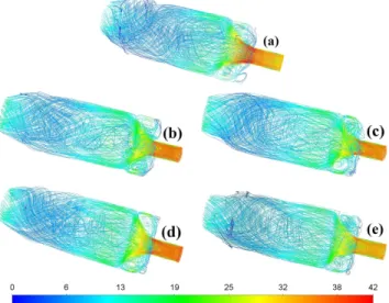
Figure 8 shows the streamlines in the whole domain, fea- turing the IRZ and ORZ in all cases. At first glance, the flow fields are identical in every case. However, NG shows a strong root due to flashback. BG40 has the highest overall velocity among the biogases in the reaction zone. The V-shaped regime of BG32H20 is confined to a relatively small volume since the high H2 content enhances the combustion process. The remainder cases with 10 V/V% H2 show a more uniform velocity field where the ORZs are involved in the flow field in a higher extent. However, also the higher CH4concentration in
5 10 15 20 25 30 35
-70 -60 -50 -40 -30 -20 -10 0 10 20 30 40 50 60 70 80 90 vmean[m/s]
z[mm]
NG BG40 BG36H10 BG32H20 BG54H10
Fig. 6. Mass weighted average velocities in the mixing tube.
500 700 900 1100 1300 1500 1700 1900 2100
-70 -60 -50 -40 -30 -20 -10 0 10 20 30 40 50 60 70 80 90 Tmean[K]
z[mm]
NG BG40 BG36H10 BG32H20 BG54H10
Fig. 7. Mass weighted average temperatures in the mixing tube.
Fig. 8. Time averaged stream lines colored by the mean velocity magnitude (m/s) in the case of (a) NG, (b) BG40, (c) BG36H10, (d) BG32H20, (e) BG54H10 combustion.
the fuel results in more intense combustion, hence, a stronger V regime.
The combustion zone consists of a preheating zone, a reaction zone, and a post-flame zone. The temperature is continuously rising while the heat release rate is the most intense in the middle. If the process treated as non-adiabatic, like in the present case, the flue gas starts to cool down due to losses via radiation which is typically originated from the triatomic gases like CO2 and H2O to the walls. If the local air-to-fuel equivalence ratio is low, the resulting soot particles will be the dominant species for thermal radiation.
The corresponding temperature fields are shown in Fig. 9.
Since the fuel flow rate is proportional to the LHV, NG is characterized by the highest temperature in the chamber among all fuels. In the other cases, the addition of CO2 mitigates the temperature rise since it is an inert component overall. Nevertheless, as a triatomic gas, it is an excellent third body for trimolecular reactions and may participate in the reactions as an oxygen carrier. The maximum temperature
Fig. 9. Time averaged temperature (K) distribution of (a) NG, (b) BG40, (c) BG36H10, (d) BG32H20, and (e) BG54H10 combustion.
TABLE II
MAXIMUM SIMULATED,ADIABATIC FLAME,AND MASS WEIGHTED AVERAGE TEMPERATURES AT THE MOST INTENSE SECTIONS.
Fuel Tmax [K] Tadiabatic[K] Taverage,max [K]
NG 2289 2346 2165
BG40 1979 2068 1924
BG36H10 2021 2105 1962
BG32H20 2060 2162 2002
BG54H10 2224 2232 2135
of BG54H10 approaches that of NG since H2 enhances the process in the reaction zone. BG40 has the lowest maximum and overall temperature among the fuels since it has the lowest LHV. It is followed by BG36H10 and BG32H20.
The maximum non-adiabatic flame temperatures are com- pared with the calculated adiabatic flame temperatures in Table II. Note that the latter calculation is an overall estimate of the process without considering heat transfer to the envi- ronment and neglecting dissociation and hence endothermic formation processes. In addition, the local equivalence ratio is also omitted which might result in higher simulated maximum temperatures than the calculated ones. To show an effective comparison, the mass-weighted average temperatures in a section with the highest temperature are added to the last column which are the lowest ones for each fuel.
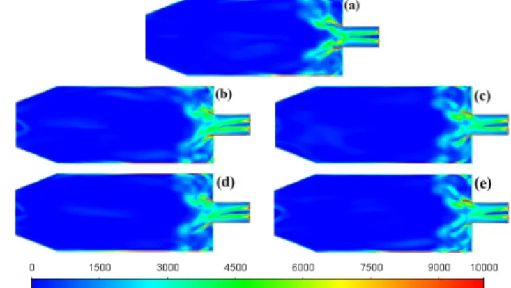
The Strain Rate is shown in Fig. 10 at different time instances. The structures are similar for all fuels, i.e., the wake of the bluff body at the inlet is notable for 40–60 mm from the inlet face in each case. There is a strong shear on the walls while a moderate shear characterizes the V regime from both the inner and outer recirculation sides. Since the ORZ is bounded by two wall surfaces, its interaction with them is notable for all cases. Following the shear at the wall of the mixing tube, it is continuous downstream the burner as well. The flashback of NG combustion does not affect the Strain Rate qualitatively, the difference is only quantitative.
The plots related to the flame shape are similar, however more intense dissipation occurred at BG40 and decreased in the function of CO2content. The highest values occurred near the wall because of the coarse mesh resolution in those regions,
Fig. 10. Strain Rate (1/s) of (a) NG, (b) BG40, (c) BG36H10, (d) BG32H20, and (e) BG54H10 combustion.
nevertheless, these did not influence the flame zone.
IV. CONCLUSIONS
Numerical analysis of a laboratory turbulent swirl burner was performed which is under construction. Natural gas combustion was taken as a reference case since it is well known in the literature. Besides that, four theoretical biogas compositions were evaluated which were simplified to CH4, CO2, and H2. The geometric swirl number was fixed at 1.15, originated from the 60◦ swirl vanes. Hence, a stable V-shaped flame was observed in all cases.
Natural gas combustion showed a slight flashback which did not affect the V-shaped flame notably. This result is acceptable since the present geometry has a bluff body at the center which is actually an airblast atomizer in the real design, hence, a small amount of air might fully put the combustion to the chamber.
The various fuels showed qualitatively similar results in all cases, the differences are practically negligible, and the real- life application might add other criteria. The OH* concentra- tions differed quantitatively with the highest concentrations of NG and BG54H10 fuels. Actually, the averaged temperature profiles of them were similar along the axis downstream of the mixing tube.
As a final result, the presented analysis proved that the analyzed biofuels can be effectively used in the designed test equipment. Hydrogen dilution in a small quantity is highly effective in combustion stabilization and is a crucial fuel component to allow the present combustion appliances to run on low calorific value fuels. However, additional investigations are required to establish a solid background knowledge and know-how for large-scale applications. These include exhaust- ing tests, emission, optical, and acoustical measurements.
ACKNOWLEDGMENT
This paper was supported by the National Research, Devel- opment and Innovation Fund of Hungary, project No. FIEK 16-1-2016-0007 and OTKA-FK 124704, New National Excel- lence Program of the Ministry of Human Capacities project No. ´UNKP-18-4-BME-195, Artificial Intelligence research
area of Budapest University of Technology and Economics (BME FIKP-MI), J´anos Bolyai Research Scholarship of the Hungarian Academy of Sciences, NVIDIA Corporation with the donation of the Quadro P6000 used for this research, and the Student Association of Energy for supporting the participation in the conference.
REFERENCES
[1] Sanjay M. Correa. Power generation and aeropropulsion gas turbines:
From combustion science to combustion technology.Symposium (Inter- national) on Combustion, 27(2):1793–1807, jan 1998.
[2] Y. Huang and V. Yang. Dynamics and stability of lean-premixed swirl- stabilized combustion. Progress in Energy and Combustion Science, 35:293–364, 2009.
[3] N. Syred. A review of oscillation mechanisms and the role of the precessing vortex core (PVC) in swirl combustion systems. Progress in Energy and Combustion Science, 32(2):93–161, jan 2006.
[4] G. Li and J. E. Gutmark. Effects Of Swirler Configurations On Flow Structures and Combustion Characteristics. InProceedings of ASME Turbo Expo 2004, Vienna, 2004.
[5] J. M. Be´er and N. A. Chigier. Combustion Aerodynamics. Robert E.
Krieger publishing company, inc., London, 1972.
[6] B. Khandelwal, D. Lili, and V. Sethi. Design and study on performance of axial swirler for annular combustor by changing different design parameters. Journal of the Energy Institute, 87:372–382, 2014.
[7] Y. Huang and V. Yang. Bifurcation of flame structure in a lean-premixed swirl-stabilized combustor: transition from stable to unstable flame.
Combustiond and Flame, 136:383–389, 2004.
[8] A. H. Lefebvre and D. R. Ballal.GAS Turbine Combustion, Alternative fuels and emissions. CRC Press, Boca Raton, third edition, 2010.
[9] A. Valera-Medina, H. Xiao, M. Owen-Jones, W. I.F. David, and P. J.
Bowen. Ammonia for power. Progress in Energy and Combustion Science, 69:63–102, 2018.
[10] U. I. Khan, M. H. D. Othman, H. Hashim, T. Matsuura, A. F. Ismail, M. Rezaei-dashtarzhandi, and I .Wan. Azelee. Biogas as a renewable energy fuel – A review of biogas upgrading , utilisation and storage.
Energy Conversion and Management, 150:277–294, 2017.
[11] K. K. Gupta, A. Rehman, and R. M. Sarviya. Bio-fuels for the gas turbine: A review. Renewable and Sustainable Energy Reviews, 14:2946–2955, 2010.
[12] Y. Qian, S. Sun, D. Ju, X. Shan, and X. Lu. Review of the state-of- the-art of biogas combustion mechanisms and applications in internal combustion engines. Renewable and Sustainable Energy Reviews, 69:50–58, 2017.
[13] B. C¸ eper, S. O. Akansu, N. Kahraman, and ˙I. G¨okalp. Investigations On The Performances And Emissions Of A Spark Ignition Engine Fuelled By Biogas.Fuels And Combustion In Engineering, pages 16–24, 2017.
[14] A. Greco, D. Mira, and X. Jiang. Effects of fuel composition on biogas combustion in premixed laminar flames. Energy Procedia, 105:1058–
1062, 2017.
[15] G. Sarras, Y. Mahmoudi, L.D. Arteaga Mendez, E.H. van Veen, M.J.
Tummers, and D.J.E.M. Roekaerts. Modeling of Turbulent Natural Gas and Biogas Flames of the Delft Jet-in-Hot-Coflow Burner: Effects of Coflow Temperature, Fuel Temperature and Fuel Composition on the Flame Lift-Off Height.Flow Turbulence Combust, 93:607–635, 2014.
[16] V. J´ozsa and A. Kun-balog. Effect of quarls on the blowout stability and emission of pollutants of a liquid-fueled swirl burner. Journal of Engineering for Gas Turbines and Power, 140(11):111502, 2018.
[17] A. Elorf, B. Sarh, F. Tabet, S. Bostyn, M. Asbik, S. Bonnamy, J. Chaoufi, T. Boushaki, and G. Pascale. Effect of Swirl Strength on the Flow and Combustion Characteristics of Pulverized Biomass Flames.Combustion Science and Technologyand Technology, 2018.
[18] M. Casey and T. Wintergerste. ERCOFTAC Best Practice Guidelines.
Fluid Dynamics Laboratory Sulzer Innotec, 2000.
[19] F Biagioli, A Scarpato, and K J Syed. Dynamic response of swirl stabi- lized turbulent premixed flames based on the Helmholz-Hodge velocity decomposition. In Electronic proceedings of the 9th Mediterranean Combustion Symposium, page 12, 2015.
[20] A. Mameri and F. Tabet. Numerical investigation of counter-flow dif- fusion flame of biogas-hydrogen blends: Effects of biogas composition, hydrogen enrichment and scalar dissipation rate on flame structure and emissions.International Journal of Hydrogen Energy, pages 1–12, 2015.
[21] LumaSense Technologies. Table of emissivity of various surfaces.
Mikron Instrument Company, Inc., Schaffhausen, 2003.
[22] Viktor J´ozsa and Attila Kun-Balog. Stability and emission analysis of crude rapeseed oil combustion. Fuel Processing Technology, 156:204–
210, 2017.
[23] Antoine Renaud, S´ebastien Ducruix, Philippe Scouflaire, and Laurent Zimmer. Flame shape transition in a swirl stabilised liquid fueled burner.
Proceedings of the Combustion Institute, 35(3):3365–3372, 2015.
[24] Fares A. Hatem, Ali S. Alsaegh, Mohammed Al-Faham, and Agustin Valera-Medina. Enhancement flame flashback resistance against CIVB and BLF in swirl burners. Energy Procedia, 142:1071–1076, 2017.
[25] C. S. Panoutsos, Y. Hardalupas, and A.M.K.P. M K P Taylor. Numerical evaluation of equivalence ratio measurement using OH* and CH*
chemiluminescence in premixed and non-premixed methane-air flames.
Combustion and Flame, 156(2):273–291, 2009.
[26] X. Liu, A.M. Elbaz, C. Gong, X.S. Bai, H.T. Zheng, and W.L. Roberts.
Effect of burner geometry on swirl stabilized methane/air flames: A joint LES/OH-PLIF/PIV study. Fuel, 207:533–546, 2017.
[27] K.K. Kuo and Acharya R. Fundamentals of Turbulent and Multiphase Combustion. John Wiley & Sons, Inc., Hoboken, New Jersey, 2012.

![Figure 4 shows the distribution of the OH* mass fraction since this variable closely related to the heat release rate [25]](https://thumb-eu.123doks.com/thumbv2/9dokorg/783519.36223/3.918.86.445.888.1034/figure-shows-distribution-fraction-variable-closely-related-release.webp)