Microelectronic Engineering 239-240 (2021) 111523
Available online 10 February 2021
0167-9317/© 2021 The Author(s). Published by Elsevier B.V. This is an open access article under the CC BY-NC-ND license
(http://creativecommons.org/licenses/by-nc-nd/4.0/).
Research paper
An integrated electro-optical biosensor system for rapid, low-cost detection of bacteria
D aniel Petrovszki ´
a,b,*, S ´ andor Valkai
a, Evelin Gora
a, Martin Tanner
a, Anita B ´ anyai
c, P ´ eter Fürjes
c, Andr ´ as D ´ er
aaInstitute of Biophysics, Biological Research Centre, Szeged, Hungary
bDoctoral School of Multidisciplinary Medical Sciences, University of Szeged, Hungary
cInstitute of Technical Physics and Materials Science, Centre for Energy Research, Budapest, Hungary
A R T I C L E I N F O Keywords:
Dielectrophoresis Microfluidics Integrated optics Biosensors
Escherichia coli bacteria Light scattering
A B S T R A C T
In medical treatment, the detection of pathogens at an early stage of diseases is a key step to set up an appro- priate diagnosis. To reach this goal, several techniques have been elaborated for point-of-care diagnostic ap- plications. One of the state-of-the art methods is the application of biosensor devices. Label-free versions of them ensure an appropriate detection of pathogens from fluid samples by their relative sensitivity, rapidity and portability, thus offering a feasible and affordable alternative to the traditional diagnostic techniques. The aim of the present study is to fulfill these requirements with a cheap construction of an electro-optical biosensor, for application as a rapid test in clinical diagnostics. Hence, an integrated microsystem consisting of dielectropho- retic surface-electrodes, a rib waveguide and a microfluidic channel was created for label-free optical detection of bacteria from fluid samples. To model the efficiency of the sensor, we carried out quantitative measurements by observing the light scattered by living Escherichia coli cells located in the vicinity of the waveguide. A sig- nificant change in the scattered light pattern was observed even when objectives of moderate magnification (x10, x4.7) were used, implying that such type of sensing of the cells can be achieved by low-cost cameras, as well. The optimal frequency utilized in the process of dielectrophoretic cell-collecting was also established. With this novel system, a detection limit of ca. 102CFU ×mL−1 was achieved, which is relevant to characteristic pathogen concentrations in body fluids, e.g., urine. Our further plan is to utilize this cell-gathering method in other, highly sensitive integrated optical sensor constructions, as well. The working principle of this dielectrophoretically enhanced detection of Escherichia coli cells from their suspensions gives us a low-cost and rapid-sensing alter- native to routinely used, but time- and money-consuming other methods. Hence, we expect it to be readily applicable in point-of-care diagnostics as a basis of rapid tests to identify general pathogens from various body fluids.
1. Introduction
In different fields of everyday life, e.g. in medical treatment, food quality control, or biodefense, there is a strong need to detect or monitor pathogens as early as possible. Fortunately, several detecting and descriptive techniques are known for these purposes [1]. The conven- tional ones, including immunoassays and microbiology culture tech- niques – enzyme-linked immunosorbent assay (ELISA) or polymerase chain reaction (PCR) based systems – have been widely used. However, in regions with poor healthcare these methods are not feasible or affordable, because of their time-consuming processes – e.g., different
steps of sample preparation and detection –, the high costs of reagents, or the necessity of high-tech diagnostic devices and laboratory experts.
In these cases, cost-effectiveness, portability, small amount of required sample and rapid, properly sensitive and specific operation are also critical factors to ensure appropriate pathogen detection [2]. To fulfill these requirements, widespread applications have been investigated in the last two decades for point-of-care diagnostic purposes. The most popular methods apply biosensor systems with microfluidic channels.
These devices can detect analytes of low concentrations from small sample volumes, thus they are widely used in the field of molecular biology, infectious disease management [3], food safety [4] and
* Corresponding author.
E-mail address: petrovszki.daniel@brc.hu (D. Petrovszki).
Contents lists available at ScienceDirect
Microelectronic Engineering
journal homepage: www.elsevier.com/locate/mee
https://doi.org/10.1016/j.mee.2021.111523 Received 8 October 2020;
biodefense [5]. One of their advantages compared to the conventional methods means that they can collect pathogens at the same place where the identification and measurements are carried out. Thus, it makes the detecting method easier, and reduces the time required for diagnosis, which helps finding the appropriate treatment in medical practice [6].
In these systems, various principles can be used for detection. Besides the systems using direct visualization of pathogens under the micro- scope, chemical-biological interactions can be used for quantification and identification by other detectors. Depending on the physical prop- erty of the captured signal, we can talk about electrical, electrochemical, optical or magnetic devices. Note that there are some cases where signal amplification is required, e.g. for optical detection purposes optical re- porters, e.g. fluorophore dyes [7], metallic nanoparticles, or quantum dots [8] can be used. Moreover, another aspect of their differentiation is whether labeling is required in the detection process. While label-using techniques are usually more accurate, their cost is higher at the same time. Hence, nowadays label-free applications are also commonly used in point-of-care diagnostics.
One type of the generally used biosensors of label-free detection is based on impedance measurements. Due to their simplicity and adapt- ability, a lot of applications for pathogen detection can be found [9]. For reasons of portability and simplicity, these devices normally contain interdigitated microelectrode arrays to reach proper sensitivity, while keeping the size of the electrode-system reduced. To improve the sensing capability in these systems, dielectrophoresis (DEP) has been also uti- lized [10,11], in order to ensure appropriate analyte detection. Several studies show that this phenomenon is applicable for bacterial cell- separation or cell-concentration [12], as well as isolating bacterial cells from fluid samples [13].
Optical biosensors are used in other promising label-free sensing approaches, which are known for safety, rapidity and multipurpose capability combined with high sensitivity [14]. These devices take advantage of the different features of light to facilitate extremely sen- sitive detecting. In recent years, integrated optical applications have been extensively studied, where an optical waveguide is the key element in the detection process. Several studies [15,16] have shown that these sensor systems can be used for the recognition of pathogens. Although, their detection methods are very diverse, they are found very sensitive, in general. In the literature, evanescent-field sensing is the basic working principle of many widely used techniques that proved to be very good in high-sensitivity, specific detection purposes [16]. Here it is necessary to mention optical waveguide light-mode spectroscopy (OWLS) [17,18]
and interferometric methods – e.g. Mach-Zehnder interferometer (MZI)- based [19,20] and surface plasmon resonance (SPR) techniques [21] – that can detect bacteria or other pathogens from fluid samples. Common to these devices is that they utilize specific adsorption onto a waveguide surface and convert the accompanying phase shift of the guided light to intensity changes measured by photodetectors. Horv´ath et al. demon- strated the applicability of an OWLS device by reaching a 60 cells x mm−2 detection limit for Escherichia coli K12 bacteria from fluid sample [17]. This technology based on optical grating has also been applied for label-free sensing of other pathogen microorganisms, as well. Another study [18] presented an OWLS device which was used for the detection of Legionella pneumophila in water, where the biorecognition elements were antibodies. Besides the grating technology, interferometric detec- tion is also among the promising label-free optical biosensing applica- tions. Mathesz et al. presented an integrated optical interferometric biosensor, which device could detect Escherichia coli bacteria from fluid samples with a detection limit of 106CFU ×mL−1 within a few minutes [19]. Moreover, another interferometric MZI immunosensor device showed a promising performance for the detection of Listeria mono- cytogenes, which pathogen can be lethal for humans. High specificity over other pathogen microorganisms was reached by this device. The biosensor achieved a limit of detection (LOD) of 105CFU ×mL−1, which is below the infection dose [22]. In a recent review [21], emerging ap- plications of SPR biosensors using modified detecting techniques have
been overviewed. One of them, namely, applied the SPR method to detect E. coli O157:H7 pathogenic bacteria, using T4 bacteriophages as recognition elements, while another highly specific phage was used to detect Staphylococcus aureus (MRSA), as well. This system could achieve label-free, specific, rapid (less than 20-min) detection of pathogens, for concentrations of 105CFU ×mL−1. In another example, an alternative version of SPR was used, where the sensing process was combined with imaging. A case study [23] showed that a charge-coupled device along with image processing methods is applicable for detection. Hence, this technique was found suitable for studying and monitoring molecular interactions in real-time, as well. In another approach, imaging-based sensing of scattered light was used in several studies – containing charge-coupled device readout systems – in order to identify and detect pathogens from fluid samples [24]. Related to this scattered light in- tensity detecting method, a commercially available optical sensor sys- tem, namely the MIT 1000 (Micro Identification Technologies Ltd., San Clemente, California, USA) also uses scattered light for the detection of pathogen bacteria from fluid samples. It analyses the back-scattering pattern of incident laser light both from the outer surface and from the internal part of bacteria. This manufacturer claims that 10–50 CFU
×assay−1 can be detected by the device.
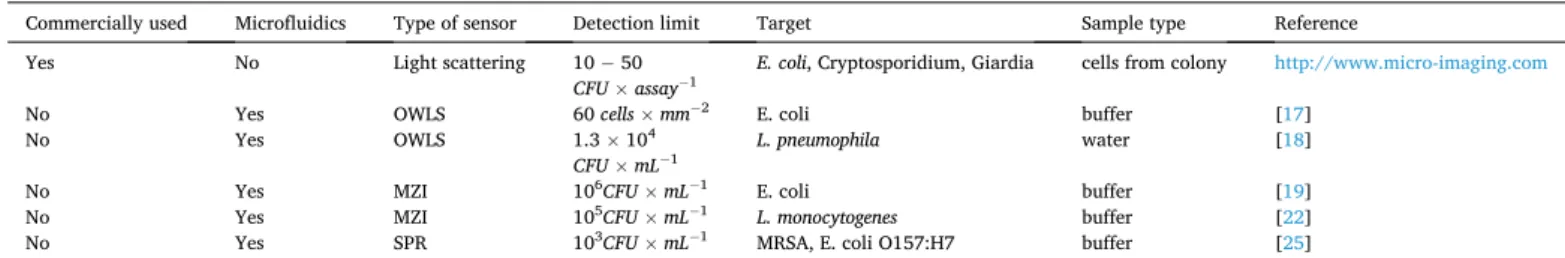
There are many different biosensor constructions available today, and the ones applying label-free methods are especially suited for rapid tests in medical diagnostics, hence they are in the forefront of related research. Table 1. shows a comprehensive review of the performance of the evanescent-wave based, label-free biosensing techniques, indicating the sensing method, the limit of detection (LOD) and the target pathogen microorganism.
In this paper we present a biosensing system, which can detect bacterial cells from low-volume fluid samples. This detection method combines a dielectrophoretic cell-collecting technique with evanescent- field sensing. After a detailed description of the device, we demonstrate the working principle of the system via a dielectrophoretically enhanced detection of Escherichia coli Dh5α cells from their suspensions, as a low- cost and rapid alternative of other, relatively sensitive methods.
2. Materials and methods
2.1. The working principle of the biosensor 2.1.1. Dielectrophoretic cell-collecting
Considering higher sensitivity, it is a crucial requirement in our sensor construction to collect the analyte particles adjacent to the sensor surface, to make them detectable by the device. To fulfill this need, we applied the phenomenon of dielectrophoresis (DEP), which is based on the dielectric polarization of particles (i.e., cells in our case). In micro- fluidic systems containing dielectric particles a dielectrophoretic force (DEP-force) awakes by applying inhomogeneous alternating electric field, that attracts (or repels) the analytes towards the electric field maxima or minima. If the force directs to the maximum field strength, we speak about positive dielectrophoresis, while the opposite effect is called negative dielectrophoresis [26]. The equation of DEP-force (Eq.1.) including the relative permittivity of the target particles compared to the surrounding medium and the frequency of the applied electric field can be described for spherical particles, as follows:
FDEP=2πr3εmRe
⎡
⎣ (
ε*p− ε*m )
ε*p+2ε*m
⎤
⎦∇Erms2 (1)
where r is the radius of the sphere, εp*, εm* are the complex permittivity for the particles and for the medium respectively, εε*p*p+2ε−ε*m*m is the Clausius- Mossotti factor, which is a parameter of the relative polarizability of the particle, and Erms is the root-mean-square of the applied alternate elec- tric field [27].
By adequate definition of characteristic parameters of the applied alternating electric field, the mentioned specific cell-collecting or cell- separating microfluidic devices can be designed [12]. A promising approach is to apply this cell-collecting method in biosensing systems developed for medical diagnostics.
2.1.2. Evanescent-field sensing via light scattering
One type of the integrated optical biosensors is based on evanescent- field sensing. In this case the light propagates in a miniature waveguide structure by total internal reflection and the output light intensity is influenced by any change in the environment. It can be caused by e.g.
the bonding of the particles on the surface [28]. In such integrated op- tical systems, the propagating waves penetrate the surrounding media to a limited extent (“evanescent-field”), allowing the detection of target molecules adjacent to the waveguides (Fig. 1a)).
There are various options to carry out quantitative measurements using this method. One of them is to measure the light that the target particles – bound to the surface of the waveguide structure – scatter, while other approaches use e.g. interferometric detection [14].
Regarding the practical applications, a crucial feature of all integrated optical biosensors is their sensitivity. In case of detecting bacteria or other cells from body fluids, increasing the cell concentration on the detector surface is a crucial requirement, where the above mentioned dielectrophoretic cell-concentrating technique can play an important role.
2.2. Device fabrication
2.2.1. Combined thin-film gold electrode and integrated optical system In the architecture of the biosensing device, the dielectrophoretic cell-collector electrode system was prepared by fabricating gold surface- electrode pairs with tilted fingers optimized for positive dielectropho- resis. The structure of this system is inspired by the design of a previous study [29], where electrode-pairs were used for cell-focusing in a microfluidic channel. Nevertheless, for the integrated sensing optical structure, a rib waveguide stripe was made within the gap of the
electrodes, as it can be seen in Fig. 1b). Hence, the cells captured in the evanescent region of the waveguide can be detected by a photodetector, since they become elementary sources of scattered light in that region.
For manufacturing both the appropriate electrode system and wave- guide structure, direct laser writing technique (μPG-101 machine, λ = 405nm, Heidelberg Instruments GmbH., Heidelberg, Germany) was used.
As the first step of the device fabrication, the electrodes were structured utilizing lift-off lithography technique following the protocol of the manufacturer of the applied materials. A positive S1818 photo- polymer (MicroResist Technology GmbH., Berlin, Germany) layer was spincoated (3000 rpm, 60 s) in the thickness of 2 μm on a microscope coverslip (Menzel-Gl¨aser, Thermo Fisher Scientific, Waltham, Massa- chusetts, USA), which step was followed by soft baking (115 ◦C, 1 min).
Then the photopolymer was exposed by the direct-laser writing appa- ratus, forming the desired structure of the tilted electrode-pairs. After- wards, the coverslip was rinsed (90 s) in the developer solution of the photopolymer (MICROPOSIT MF-319 solution, Kayaku Advanced Ma- terials, Inc. (formerly MicroChem Corp.), Westborough, Massachusetts, USA) and was washed by deionized (18.2 MΩ) MilliQ water (Synergy® UV Water Purification System, Merck-Millipore, Burlington, Massachu- setts, USA) to remove the exposed part of the polymer. As a result, a mask was made containing the design of the electrodes. Next, the coverslip was exposed again by Mercury i-line UV light (Oriel 97,435 UV lamp, λ ≈365nm, Newport Corp., Irvine, California, USA), in order to remove the remained part of the photopolymer from the surface by a repeatedly applied developing step. After the exposure, homogeneous chromium and gold layers were deposited by sputtering technique.
During this process, the chamber was pumped to high vacuum (8 ×10⁻² mbar), and Argon gas was used to generate sputtering ions during the process. At first a 10 nm thick Cr layer was deposited in order to enhance the gold layer adhesion to the glass surface. Then a 30 nm thick Au layer was deposited. Next, the mentioned developing step was performed. In this step, the coverslip was rinsed in the solution for a two-day long period to remove all the photopolymer from its surface. After that, the coverslip was dried and then was used as a substrate for the further Table 1
Recent results of various integrated optical biosensor constructions for pathogen detection.
Commercially used Microfluidics Type of sensor Detection limit Target Sample type Reference
Yes No Light scattering 10 − 50
CFU ×assay−1 E. coli, Cryptosporidium, Giardia cells from colony http://www.micro-imaging.com
No Yes OWLS 60 cells ×mm−2 E. coli buffer [17]
No Yes OWLS 1.3 ×10⁴
CFU ×mL−1 L. pneumophila water [18]
No Yes MZI 106CFU ×mL−1 E. coli buffer [19]
No Yes MZI 105CFU ×mL−1 L. monocytogenes buffer [22]
No Yes SPR 103CFU ×mL−1 MRSA, E. coli O157:H7 buffer [25]
Fig. 1. a) shows the schematic illustration of the evanescent-field sensing, where the bonding of the Escherichia coli bacteria to the surface of the waveguide cause scattering of the evanescent waves of the light propagating in the waveguide. Fig. 1b) illustrates the schematic design and realization of the integrated optical biosensor system (the figure was created with Biorender.com).
steps.
Next, the integrated optical waveguide structure was fabricated.
During this process the deposited substrate – containing the electrode system – was covered by a 2-μm thick negative photopolymer (Epo- Core_2, MicroResist Technology GmbH., Berlin, Germany) by spincoat- ing (3000 rpm, 60 s). Then it was prebaked in two steps (first at 50 ◦C for 2 mins, then with even heating at 90 ◦C for 2 mins). After the coverslip was cooled down to room temperature (approx. After 30 mins), the photopolymer was exposed by direct laser writing for the rib waveguide strip localized in the 10 μm gap between the tilted electrode pairs. Af- terwards, the coverslip was postbaked in two steps (first at 50 ◦C for 2 mins, then with even heating at 85 ◦C 3 mins). As in the case of pre- baking, after the substrate was cooled down to room temperature, it was rinsed (90 s) in the developer of the photopolymer (mr-Dev 600 devel- oper solution, MicroResist Technology GmbH., Berlin, Germany) and was washed by isopropanol. After these steps of the fabrication, a combined biosensing system consisting of sensing integrated optical waveguide strip and cell-collecting electrode system was realized (Fig. 1b.)). These are the two key components of the integrated optical sensor device.
2.2.2. Microfluidic channel
In our construction, the purpose is to detect bacteria from small sample volumes. Therefore, a microfluidic channel was required to ensure the continuous flow of these fluids. During the preparation pro- cess of this PDMS (poly(dimethylsiloxane)) channel, soft lithography technique was applied following the steps described in the previous work of our research group [19]. First a mold was fabricated by using a SU-8 negative photoresist. As a first step of the fabrication, a 15-μm thick photoresist layer was spincoated on a glass substrate, and then soft- baked (90 ◦C, 5 min). Afterwards, it was exposed through a photo- mask by UV light (Oriel 97,435 UV lamp, λ ≈365nm, Newport, Corp., Irvine, California, USA). Next, a liquid PDMS prepolymer (degassed 1:10 mixture of Sylgard 184, Dow Corning, Midland, Michigan, USA) was poured over the master mold and cured for 30 min at 80 ◦C. Subse- quently, the replica of the PDMS was peeled from the master structure and adequate holes were pierced at inlets and outlets for pipette tips. To finish the process, the PDMS was bonded above the tilted fingers region of the electrode-pairs, including the sensing rib waveguide structure in the gap between them (Fig. 1.b)).
2.3. E. coli suspension preparation
In this study, only non-virulent, living E. coli cell cultures of Dh5α strain were used. Prior to use, the colonies were kept on agar plates at 4 ◦C. For the experiments, the cells were pipetted into 3 mL LB (lysogeny broth) medium in a sterile polystyrene tube. Then the bacteria were grown overnight in a shaker incubator at 30 ◦C. Next morning, these cultures were diluted back 100 times. Then cells were grown until they reached the optical density of 0.4 at 600 nm (OD600). In the meantime, an Eppendorf-tube was filled with 1350 μL sterile-filtrated (0.2 μm pore size cellulose acetate sterile syringe filter, VWR International, Radnor, Pennsylvania, USA) master dilution solution of LB and MilliQ deionized water (1:9 ratio). Next, 150 μL of the cell culture was pipetted into this tube and was resuspended. Note, that samples spiked by dielectric particles, e.g. LB solution, must be diluted to lower ionic strengths for the optimal working of the applied DEP collecting electrode system, the dielectric particles filled samples and to avoid undesired side-effects, i.
e., electrolysis of the fluid and the damages to electrodes. Prior to the experiments, the desired concentration of E. coli suspensions was adjusted. The concentration of the undiluted bacteria in the LB culture was determined by plate counting technique and expressed in colony forming units per milliliter (CFU ×mL−1).
During the experiments aiming at the size selectivity of the applied cell-collecting method, a mixture of living E. coli and hCMEC/D3 (Human Cerebral Microvascular Endothelial Cell Line) cell cultures was
diluted by the master dilution mixture, following the same protocol that used for E. coli suspension dilution, but in this case negative artificial urine (pH =5.94) was used to replace the LB in the solution (artificial urine and deionized water in the ratio of 1:9 respectively). The hCMEC/
D3 (Human Cerebral Microvascular Endothelial Cell Line) cells were grown in an incubator and were diluted back prior to the mixing step.
The urine solution was prepared on the basis of the protocol of negative artificial urine base solution recipe ("Case A" in the study of Khan et al.
[30]), with the following modifications. Firstly, the base solutions were made by diluting 1.3609 g KH2PO4 (0.1 M) and 2.2823 g K2HPO4 (0.1 M) in 100 mL-100 mL deionized water. Then, the applied urine solution was prepared by mixing the two solutions in 2:1 ratio respectively.
Finally, 7.5 mg Tween-20 (Sigma-Aldrich, St. Louis, Missouri, USA) was added to the 150 mL of the final negative artificial urine solution (pH = 5.94) to avoid aggregation.
2.4. Experimental setup
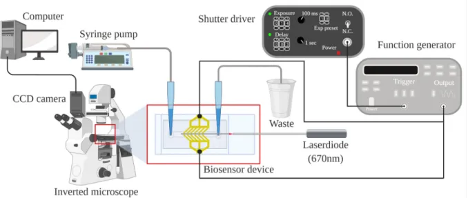
In this study, the fluid sample was pumped into the microfluidic channel at a constant flow rate by a syringe pump (SP210IWZ syringe pump, World Precision Instruments Inc., Sarasota, Florida, USA). The system was monitored by a CCD camera attached to an inverted mi- croscope (Zeiss Axiovert 200, Jena, Germany) and connected to a computer, that was also used to capture optical images during scattered- light detecting experiments. AC electric field at various frequencies was applied for generating positive DEP, for optimizing the collecting capability of the electrode system coupled to a function generator (20 MHz function generator model 8020, Tabor Electronics Ltd., Nesher, Israel) with sinusoidal signals. Switching on and off the voltage was controlled via square wave trigger signals (TTL, 1.4 s) from a timer (Uniblitz VS14S2ZM1R1–21, Vincent Associates, Rochester, New York, USA). The light beam of a laser diode (λ = 670nm) was used for measuring and was coupled to a single-mode optical fiber (S630-HP, Thorlabs), whose other end was matched to the input of the waveguide by a micropositioner (DC-3 K, M¨arzh¨auser Wetzlar GmbH & Co. KG, Wetzlar, Germany), and its optimal position was fixed by a photo- polymer glue (OP-66-LS, Dymax Europe GmbH, Wiesbaden, Germany).
Fig. 2 shows the experimental setup of the realized biosensor system.
3. Results and discussion 3.1. Dielectrophoretic cell-collecting
Regarding the sensitivity of the detection method, testing the cell- collecting capability of the thin-film electrode system was crucial.
(Note, that these experiments were performed prior to the detecting experiments, and the device did not contain the detecting waveguide structure.) As a first step, we tested the particle-collecting capability and the size-wise selectivity of this method by injecting a mixture of deionized MilliQ water (Synergy® UV Water Purification System, Merck-Millipore, Burlington, Massachusetts, USA) and polystyrene beads (Polybead® Microspheres, Polysciences Inc., Warrington, Penn- sylvania, USA) of different diameters (1 μm, 9 μm) into the microfluidic channel. During these experiments, the fluid sample was pumped at the flow rate of 5 μL ×min−1, while alternating electric field current (30 Vp−p, 5 MHz) was applied to achieve the desired positive dielectropho- retic collection of the target particles. The results met our expectations.
Applying this method, we could attract the polystyrene beads of the desired 1 μm diameter to the surface of the gap between the electrodes, whilst it did not cause any change in the movement of the beads of 9 μm diameter in the mixture.
Based on these measurements, the next step was to replace the polystyrene bead target particles with non-virulent, living Escherichia coli cells, to collect pathogens from their diluted samples utilizing this phenomenon. In this case, we used bacterial suspensions of various di- lutions, in order to determine the sensitivity of our system. The protocol
of the experiment was the same as the one used in case of the polystyrene beads. During each cell-collecting process, the E. coli bacteria suspension was pumped at a flow rate of 5 μL ×min−1 for a half-an-hour-long period after the application of alternating electric field. First, we examined the applicability of the mentioned surface-electrode system in case of a bacterium suspension of 106CFU × mL−1concentration. In this case effective cell-collecting could be observed shortly after the experiment started (Supplementary Experimental Data – Videos: VideoS1-Cell- collecting). Following the experiments with further diluted E. coli sam- ples, we observed that a high ratio of the analyte cells was collected from the diluted suspension of bacteria of a concentration of 104CFU ×mL−1 as well. Hence, this lower-concentration sample seemed applicable for our detecting purposes, to perform quantitative measurements for optimizing the crucial parameters of the detecting system, namely, to choose optimal magnification and AC frequency.
3.2. Detection via evanescent-wave scattering: Image capturing and analysis
3.2.1. Optimization of the experimental parameters
During the biosensing experiments, the measuring system included the detecting waveguide structure, too. After completing the he above- described dielectrophoretic cell-collecting process for 30-min, the alternating electric field was turned off (“OFF state”) and then on (“ON state”) again, by giving short, 1.4-s long pulses with three-second long pauses, hence, periodically changing the adhesion contact between the cells and the surface of the waveguide. The subsequent changes in the pattern of the scattered-light intensity image could be observed and captured, too. Based on microscopic observations, these changes correlated, and hence, were attributed to the movement of bacteria due to switching on and off the alternating electric field. (Note that during these experiments only bacterial cells were present in the suspension.) This procedure gave the basics of the quantitative detection. Note that the short duration of the pulse periods was crucial to avoid the removal Fig. 2. Schematic illustration of the experimental setup. The sample was pumped through the microfluidic channel by a syringe pump, the red light of a laser diode was coupled to the waveguide by a single mode optic fiber, and the electrodes were connected to the signal generator controlled by a shutter-driver timer. Image capturing was carried out by the CCD camera of an inverted microscope connected to the computer, where image processing was performed. (The figure was created with BioRender.com).
Fig. 3. The image-analysis assisted, quantitative measurement, which is based on the recorded scattered light intensity images, while the inhomogeneous alternating electric field is switched on and then off, inducing bacteria movement and change in the scattered image patterns. (The figure was created with BioRender.com.)
of collected bacteria from the sensing region. During this period of the measurement process, several image pairs were captured from the same cross-section of the system in different states (OFF and ON). The whole detection period lasted about 40 mins, including the cell-collecting step.
The schematic illustration of E. coli cell detection based on the evanescent-wave scattering process is shown in Fig. 3. Further details of the measurements can be found in the Supplementary Experimental Data – Videos: VideoS2-Magnification-test.
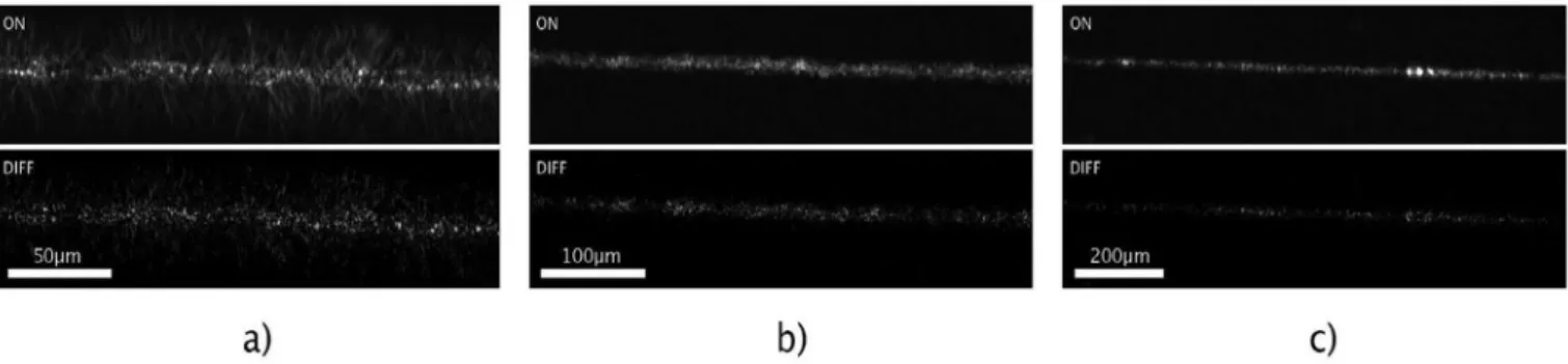
During the follow-up tests, objectives of different magnifications (x4.7, x10, x20) were used for image capturing of the scattered light, in order to define the applicable resolution where the change in the scat- tered light intensity image is significant. For demonstration, light- intensity difference images were calculated for a diluted (104CFU × mL−1) bacterium suspension, showing the change in the scattered light pattern (Fig. 4).
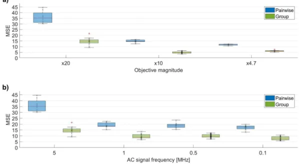
For making these measurements quantitative, image processing methods were applied, in order to determine the similarities and dif- ferences between the captured scattered light patterns. To achieve this goal, a script and a function was written in MATLAB2017b, in order to calculate appropriate variables to describe the similarities between the images. Hence, correlation and mean-squared error (MSE) values were calculated for every captured image pair, based on image processing functions of MATLAB, e.g. corr2() or immse(). To determine whether the scattered light pattern was changed significantly between the OFF and ON states of the system, the same calculations were performed also for different images recorded in the same state (OFF-state and ON-state images), which served as control groups. The results of the image analysis (number of image pairs: n =5–12, Supplementary Experimental Data - Tables: TableS1-Optimization) clearly show that there was sig- nificant difference in the MSE values between the image pairs (OFF-ON images) compared to the fluctuations within control groups (Fig. 5a)-b).
It could be established that significant differences for MSE values were observed in those cases, too, where the detection was carried out by objectives with less magnification (x4.7, x10) (Fig. 5a, and Supple- mentary Experimental Data – Tables: TableS1-Optimization).
Thereafter, a second set of experiments was carried out to optimize the collecting process in the DEP cell by determining the ideal frequency of the applied alternating electric field, where most bacteria cells can be collected (Supplementary Experimental Data – Videos: VideoS3- Frequency-test). For this purpose, the frequency range of 100 kHz to 5 MHz was applied, and, using the above protocol for quantitative image processing, it was established that the 5 MHz frequency yielded the best results for dielectrophoretic cell-collecting (Fig. 5b), and Supplementary Experimental Data – Tables: TableS1-Optimization), a process crucial from the point of view of sensitivity.
3.2.2. Determination of the sensitivity of the method
After optimizing the AC frequency and the optical magnification,
further experiments aiming to determine the detection limit of this sensing system were carried out. To this end, we used a serial dilution of samples of 102 − 106CFU ×mL−1 concentration, to collect and detect bacteria cells from fluid samples, using the optimal measuring condi- tions (the objective of x20 magnification and the optimized AC param- eters (30 Vp-p, 5 MHz, sinusoid signal)). Moreover, experiments revealing the kinetics of the dielectrophoretic cell-collection were also performed to reduce the time period required for determining the most significant scattered-light pattern changes. For this purpose, capturing of the scattered light intensity images was performed for each of the serial diluted bacteria suspensions, with a collecting period time of 0 (n
=5), 1 (n =10), 3 (n =6–10), 10 (n =19–20) and 30 (n =20) minutes (Supplementary Experimental Data – TableS2-Sensitivity). Note, that here the 0-time values correspond to reference measurements. In these cases, mean-squared-error image similarity values were calculated for each image pairs (OFF and ON state), and for each group images. Based on the image processing results, an optimal cell-collecting period time of 10 mins was estimated. Fig. 6a) shows the results (n =19–20) of the scattered light intensity image processing for the serial diluted bacteria suspensions with 10-min long cell-collecting. (Further details are found in the Supplementary Experimental Data – Tables: TableS2-Sensitivity) The resulting data clearly shows that a significant difference can be found in the MSE values of the pairwise images compared to the group ones even for the lowest, 102CFU ×mL−1 bacteria concentration. The tendency of this difference in the MSE values between the pairwise and group data for the bacteria samples is indicative of the collected number of bacteria, which can be used for the calibration of the sensor system.
For this purpose, this difference was calculated utilizing the mean MSE values of the pairwise and group data. Since this experiment was per- formed on the same biosensor, a reference MSE difference value was calculated using the images from the first detection step of the process, where no bacteria cells were collected. Then this value was extracted from every MSE difference value, and the resulting differences between the MSE values of the pairwise images and the group ones are shown in Fig. 6b). A power-law function could be fitted to these values, with a multiplication factor of 0.6152, and an exponent of 0.2228. Taking into account the high goodness-of-fit value (R2 =0.91), this function can be considered to define the calibration curve for this experiment.
3.3. Experiments with artificial urine containing bacteria and somatic cells
As a pilot test focusing on the selectivity of the cell-collecting pro- cess, an artificial urine sample containing a mixture of E. coli and hCMEC/D3 endothelial cell suspensions at the concentration of 104CFU
× mL−1 was used to mimic an environment of inflammatory urine, infected by bacteria, and containing other cell types, too. During the experiment, an alternating electric field (30 Vp−p 5 MHz) was applied. At
Fig. 4.Scattered light intensity images at the same region of the biosensor system are shown after cell-collecting (104 CFU ×mL−1 E. coli suspension) at given alternating electric field parameters detected by objectives of x20 (a), x10 (b), and x4.7 (c) magnifications. The upper inserts show the scattered-light intensity pattern when the electric field is applied to the electrodes (ON), the lower ones represent the scattered intensity difference between the ON and OFF states (DIFF).
The images were evaluated by image processing.
first, the fluid sample was pumped at a flow rate of 0.1 μL ×min−1 for a couple of minutes, to observe the effect of the dielectrophoresis on the individual cells, while the sample was flowing through the channel. Due to the size-dependent behavior of the dielectrophoresis at the chosen frequency and ionic strength, collection of bacteria (~2 μm) and repel- ling of endothelial cells (~10 μm) was observed in the region of the electrode system, due to the size difference between the two cell types.
Next, a selective bacteria collecting was performed while the suspension was pumped at a higher, 3 μL ×min−1 flow rate. During the process no endothelial cell was observed to be collected on the surface of the waveguide whereas many bacterial cells were adhered on the gap be- tween the tilted-finger electrode pairs (Supplementary Experimental Data – Videos: VideoS4-Selectivity). The results of the pilot test proved a sort of selectivity of our method: bacteria were collected on the sensor Fig. 5. Image analysis of pairwise and group results (n =5–12) of experiments applying various objective magnifications (a)) and AC frequencies (b)) at a given E.
coli concentration (104CFU ×mL−1). As a quantitative descriptor of the effects, the mean-squared errors (MSE) of the scattering patterns (“pairwise” and “group”
images) were taken at the same region of the intensity images (x20 objective). The images were captured applying AC signal of 30 Vp−p amplitude and various frequencies in the range of 0.1–5 MHz. In the experiment aimed to optimize objective magnification, the applied electric field parameters were 30 Vp−p and 5 MHz.
Fig. 6. Fig. 6.a) Image analysis results of pairwise and group images (n =19–20) registered during the experiments with serial diluted bacteria suspension (102 − 106 CFU ×mL−1). As a quantitative descriptor of the image differences, mean-squared error (MSE) values between the scattering patterns were taken at the same region of the biosensor device (x20 objective). Fig. 6.b) shows the difference of the MSE values (mean±standard deviation) of the pairwise images compared to the control group ones. 6c) shows the same difference, but on a dual-logarithmic scale. 6b) and 6c) also shows that even at an extremely low bacteria concentration (102 CFU × mL−1) a significant difference can be observed between the corresponding MSE values, defining the detection limit of this novel biosensing method. A power-law function could be fitted to the data (R2 =0.91), providing the calibration curve of the method, as well.
surface between the electrodes, while endothelial cells were flowing through the microchannel above the sensor system, not interfering with the detection of pathogens.
4. Conclusions
We presented an image-analysis assisted, label-free, rapid bacterium- detecting method, and we could demonstrate its working principle with a suspension of real, living E. coli bacterial cells. Applying this detection method and choosing the optimal statistical analyzing tools (e.g.
determination of correlation, mean-squared error), a proper calibration of image similarities could be realized. The mean-squared error variable proved to be the most appropriate for this purpose. Using image pro- cessing methods, the optimization of the applied alternating current frequency was performed. Based on the image similarity results, we established that the biosensor construction can be used with a less sensitive detector (e.g., by a cheap camera). Note that, it was not necessary to observe individual cells utilizing this method, still, the change in the scattered light pattern seemed to be a good indicator of the presence of the analytes based on the results of the detection limit ex- periments. The sensitivity of the method was found to be ca. 102 CFU × mL−1. The new technique outperforms a previous interferometric biosensor construction of our working group [19], and is relevant to characteristic pathogen concentrations in, e.g., urine [31]. Moreover, this sensitivity is comparable with other label-free optical – OWLS, MZI, SPR techniques – detection methods listed in the introduction [32,33].
The detection time of the sensor was optimized in 10 min and was found to be considerably less than the ones of traditional bacterium-detecting laboratory techniques, e.g. ELISA or PCR [34]. However, the present form of the measuring technique is restricted to monitor unspecific bonding of the analyte cells on the surface of the waveguide. Still, a pilot test with artificial urine, containing a mixture of bacterial E. coli cells and hCMEC/D3 endothelial cells, proved that our sensing technique is selective for the detection of bacterial cells over somatic cells, due to the frequency- and cell-size dependent sign change of the collecting die- lectrophoretic force. In forthcoming studies, we plan to functionalize the sensor surface to reach specific bacterium cell sensing and test the sys- tem under conditions where a mixture of different pathogens is present, such as in case of body fluids. However, we believe that even in its proof- of-concept form, this detection method is very promising from the point of view of its sensitivity, low cost of fabrication, and rapid detection process. Improving the image analyzing methods and optimizing the applied codes are expected to further reduce the detection limit of our technique. We hope that in the future this detecting technique can be utilized in point-of-care diagnostics.
Supplementary data to this article can be found online at https://doi.
org/10.1016/j.mee.2021.111523.
Declaration of Competing Interest
The authors declare that they have no known competing financial interests or personal relationships that could have appeared to influence the work reported in this paper.
Acknowledgements
The authors are indebted to Drs. Andr´as Borbír´o, M´at´e Varga, K´aroly Kunst´ar, Dafni Charalambous, researchers of the 77 Elektronika Ltd., for helpful discussions and for careful reading of the text. The research was supported by Hungarian grants VEKOP-2.2.1-16-2017-00001, NKFI-6 124922, EFOP-3.6.3-VEKOP-16-2017-00009 and Laserlab-Europe, H2020-ECGA 654 148. We thank Dr. P´eter Galajda and his working group members for the usage of the laboratory and equipment, as well as to Dr. M´aria Deli and Ana-Raquel Santa Maria for providing the endo- thelial cells.
References
[1] B. Nasseri, N. Soleimani, N. Rabiee, A. Kalbasi, M. Karimi, M.R. Hamblin, Point-of- care microfluidic devices for pathogen detection, Biosens. Bioelectron. 117 (2018) 112–128, https://doi.org/10.1016/j.bios.2018.05.050.
[2] D.T. Chiu, A.J. deMello, D. Di Carlo, P.S. Doyle, C. Hansen, R.M. Maceiczyk, R.C.
R. Wootton, Small but perfectly formed? Successes, challenges, and opportunities for microfluidics in the chemical and biological sciences, Chem 2 (2017) 201–223, https://doi.org/10.1016/j.chempr.2017.01.009.
[3] C.D. Chin, T. Laksanasopin, Y.K. Cheung, D. Steinmiller, V. Linder, H. Parsa, J. Wang, H. Moore, R. Rouse, G. Umviligihozo, E. Karita, L. Mwambarangwe, S.
L. Braunstein, J. Van De Wijgert, R. Sahabo, J.E. Justman, W. El-Sadr, S.K. Sia, Microfluidics-based diagnostics of infectious diseases in the developing world, Nat.
Med. 17 (2011) 1015–1019, https://doi.org/10.1038/nm.2408.
[4] C. Adley, Past, present and future of sensors in food production, Foods. 3 (2014) 491–510, https://doi.org/10.3390/foods3030491.
[5] P. Mehrotra, Biosensors and their applications - a review, J. Oral Biol. Craniofacial Res. 6 (2016) 153–159, https://doi.org/10.1016/j.jobcr.2015.12.002.
[6] Y. Wang, L. Yu, X. Kong, L. Sun, Application of nanodiagnostics in point-of-care tests for infectious diseases, Int. J. Nanomedicine 12 (2017) 4789–4803, https://
doi.org/10.2147/IJN.S137338.
[7] F. Gaits, K. Hahn, Shedding light on cell signaling: interpretation of FRET biosensors, Sci. STKE 2003 (2003) 1–6, https://doi.org/10.1126/stke.2003.165.
pe3.
[8] G. Kim, J.H. Moon, C.Y. Moh, J. Guk Lim, A microfluidic nano-biosensor for the detection of pathogenic Salmonella, Biosens. Bioelectron. 67 (2015) 243–247, https://doi.org/10.1016/j.bios.2014.08.023.
[9] E.B. Bahadir, M.K. Sezgintürk, A review on impedimetric biosensors, Artif. Cells Nanomed. Biotechnol. 44 (2016) 248–262, https://doi.org/10.3109/
21691401.2014.942456.
[10] C. P´aez-Avil´es, E. Juanola-Feliu, J. Punter-Villagrasa, B. Del Moral Zamora, A. Homs-Corbera, J. Colomer-Farrarons, P.L. Miribel-Catal`a, J. Samitier, Combined dielectrophoresis and impedance systems for bacteria analysis in microfluidic on- chip platforms, Sensors (Switzerland) 16 (2016), https://doi.org/10.3390/
s16091514.
[11] C.D. Chin, V. Linder, S.K. Sia, Lab-on-a-chip devices for global health: past studies and future opportunities, Lab Chip 7 (2007) 41–57, https://doi.org/10.1039/
b611455e.
[12] B.H. Lapizco-Encinas, B.A. Simmons, E.B. Cummings, Y. Fintschenko, Dielectrophoretic concentration and separation of live and dead bacteria in an array of insulators, Anal. Chem. 76 (2004) 1571–1579, https://doi.org/10.1021/
ac034804j.
[13] P.R.C. Gascoyne, J. Noshari, T.J. Anderson, F.F. Becker, Isolation of rare cells from cell mixtures by dielectrophoresis, Electrophoresis. 30 (2009) 1388–1398, https://
doi.org/10.1002/elps.200800373.
[14] S.M. Yoo, S.Y. Lee, Optical biosensors for the detection of pathogenic microorganisms, Trends Biotechnol. 34 (2016) 7–25, https://doi.org/10.1016/j.
tibtech.2015.09.012.
[15] P. Kozma, F. Kehl, E. Ehrentreich-f¨orster, C. Stamm, F.F. Bier, Biosensors and bioelectronics integrated planar optical waveguide interferometer biosensors : a comparative review, Biosens. Bioelectron. 58 (2014) 287–307, https://doi.org/
10.1016/j.bios.2014.02.049.
[16] B. Chocarro-Ruiz, A. Fern´andez-Gavela, S. Herranz, L.M. Lechuga, Nanophotonic label-free biosensors for environmental monitoring, Curr. Opin. Biotechnol. 45 (2017) 175–183, https://doi.org/10.1016/j.copbio.2017.03.016.
[17] R. Horv´ath, H.C. Pedersen, N. Skivesen, D. Selmeczi, N.B. Larsen, Optical waveguide sensor for on-line monitoring of bacteria, Opt. Lett. 28 (2003) 1233, https://doi.org/10.1364/ol.28.001233.
[18] I.R. Cooper, S.T. Meikle, G. Standen, G.W. Hanlon, M. Santin, The rapid and specific real-time detection of Legionella pneumophila in water samples using optical waveguide lightmode spectroscopy, J. Microbiol. Methods 78 (2009) 40–44, https://doi.org/10.1016/j.mimet.2009.04.004.
[19] A. Mathesz, S. Valkai, A. Újv´arosy, B. Aekbote, O. Sipos, B. Stercz, B. Kocsis, D. Szab´o, A. D´er, Integrated optical biosensor for rapid detection of bacteria, Optofluid Microfluid. Nanofluidics 2 (2015) 15, https://doi.org/10.1515/optof- 2015-0002.
[20] M. Angelopoulou, P.S. Petrou, E. Makarona, W. Haasnoot, I. Moser, G. Jobst, D. Goustouridis, M. Lees, K. Kalatzi, I. Raptis, K. Misiakos, S.E. Kakabakos, Ultrafast multiplexed-allergen detection through advanced fluidic design and monolithic interferometric silicon chips, Anal. Chem. 90 (2018) 9559–9567, https://doi.org/10.1021/acs.analchem.8b02321.
[21] Z. Liao, Y. Zhang, Y. Li, Y. Miao, S. Gao, F. Lin, Y. Deng, L. Geng, Microfluidic chip coupled with optical biosensors for simultaneous detection of multiple analytes: a review, Biosens. Bioelectron. 126 (2019) 697–706, https://doi.org/10.1016/j.
bios.2018.11.032.
[22] D. Sarkar, N.S.K. Gunda, I. Jamal, S.K. Mitra, Optical biosensors with an integrated Mach-Zehnder interferometer for detection of listeria monocytogenes, Biomed.
Microdevices 16 (2014) 509–520, https://doi.org/10.1007/s10544-014-9853-5.
[23] G. Steiner, Surface plasmon resonance imaging, Anal. Bioanal. Chem. 379 (2004) 328–331, https://doi.org/10.1007/s00216-004-2636-8.
[24] M. Zourob, S. Mohr, B.J. Treves Brown, P.R. Fielden, M.B. McDonnell, N.
J. Goddard, An integrated optical leaky waveguide sensor with electrically induced concentration system for the detection of bacteria, Lab Chip 5 (2005) 1360–1365, https://doi.org/10.1039/b504938e.
[25] N. Tawil, E. Sacher, R. Mandeville, M. Meunier, Surface plasmon resonance detection of E. coli and methicillin-resistant S. aureus using bacteriophages,
Biosens. Bioelectron. 37 (2012) 24–29, https://doi.org/10.1016/j.
bios.2012.04.048.
[26] C. Yu, J. Vykoukal, D.M. Vykoukal, J.A. Schwartz, L. Shi, P.R.C. Gascoyne, A three- dimensional dielectrophoretic particle focusing channel for microcytometry applications, J. Microelectromech. Syst. 14 (2005) 480–487, https://doi.org/
10.1109/JMEMS.2005.844839.
[27] C.P. Jen, C.H. Weng, C. Te Huang, Three-dimensional focusing of particles using negative dielectrophoretic force in a microfluidic chip with insulating microstructures and dual planar microelectrodes, Electrophoresis 32 (2011) 2428–2435, https://doi.org/10.1002/elps.201100085.
[28] A.M. Hutchinson, Evanescent wave biosensors, Mol. Biotechnol. 3 (1995) 47–54, https://doi.org/10.1007/bf02821334.
[29] S.G. Dastider, A. Abdullah, I. Jasim, N.S. Yuksek, M. Dweik, M. Almasri, Low concentration E. coli O157:H7 bacteria sensing using microfluidic MEMS biosensor, Rev. Sci. Instrum. 89 (2018), https://doi.org/10.1063/1.5043424.
[30] L.B. Khan, H.M. Read, S.R. Ritchie, T. Proft, Artificial urine for teaching urinalysis concepts and diagnosis of urinary tract infection in the medical microbiology laboratory †, J. Microbiol. Biol. Educ. 18 (2017) 1–6, https://doi.org/10.1128/
jmbe.v18i2.1325.
[31] J.G. Bartlett, Laboratory diagnosis of urinary tract infections in adult patients, Infect. Dis. Clin. Pract. 12 (2004) 360–361, https://doi.org/10.1097/01.
idc.0000144910.19687.1f.
[32] N. Massad-Ivanir, G. Shtenberg, E. Segal, Optical detection of E. coli bacteria by mesoporous silicon biosensors, J. Vis. Exp. (2013) 6–13, https://doi.org/10.3791/
50805.
[33] Y. Chen, J. Liu, Z. Yang, J.S. Wilkinson, X. Zhou, Optical biosensors based on refractometric sensing schemes: a review, Biosens. Bioelectron. 144 (2019) 111693, https://doi.org/10.1016/j.bios.2019.111693.
[34] O. Lazcka, F.J. Del Campo, F.X. Mu˜noz, Pathogen detection: a perspective of traditional methods and biosensors, Biosens. Bioelectron. 22 (2007) 1205–1217, https://doi.org/10.1016/j.bios.2006.06.036.