Identification of Energy Distribution for Crash Deformational Processes of Road Vehicles
István Harmati, Péter Várlaki
Department of Chassis and Lightweight Structures Budapest University of Technology and Economics Bertalan L. u. 2, H-1111 Budapest, Hungary harmati@sze.hu, varlaki@kme.bme.hu
Abstract: Car body deformation modelling plays a very important role in crash accident analyses, as well as in safe car body design. The determination of the energy absorbed by the deformation and the corresponding Energy Equivalent Speed can be of key importance;
however their precise determination is a very difficult task. Although, using the results of crash tests, intelligent and soft methods offer an automatic way to model the crash process itself, as well as to determine the absorbed energy, the before-crash speed of the car, etc. In this paper a model is introduced which is able to describe the changing of the energy distribution during the whole deformational process and to analyze the strength of the different parts without any human intervention thus significantly can contribute to the improvement of the modelling, (automatic) design, and safety of car bodies.
Keywords: car-crash, deformational energy
1 Introduction
Accident analysis and design of safety car become rather important task. In safety vehicle design one of the most important problems is the reconstruction of the deformation. The base of this method usually a classical model of a simpler dynamical system [4] [7], which can be completed with computer based numerical solutions [8] [11]. Unfortunately these models in most of the cases become unsolvable difficult, if we apply them in a very difficult real system such as a vehicle. A possible way to solve this problem is application of soft computing methods which are very useful for example in the determining the before crash speed of the crashed car [1] [2] [3].
For construction of the optimal car-body structures, a lot of data, so a lot of crash- tests were needed. These tests are quite expensive, thus only some hundred tests per factory are realized annually, which is not a sufficient amount for accident safety. Therefore, real-life tests are supplemented by computer based simulations
which increase the number of analyzed cases to few thousands, so there is an ever- increasing need for more correct techniques, which need less computational time and can more widely be used. Thus, new modelling and calculating methods are highly welcome in deformation analysis.
Through the analysis of traffic accidents we can obtain information concerning the vehicle which can be of help in modifying the structure or the parameters to improve its future safety. The energy absorbed by the deformed car body is one of the most important factors affecting the accidents thus it plays a very important role in car crash tests and accident analysis [5] [6]. The method of the finite elements can be usefully used for simulating the deformation process, but this kind of simulation requires very detailed knowledge about the parameters and energy absorbing properties, besides this it has high complexity and computational cost. The main aim of our experiment is to develop such method, which is able to simulate the deformation process more quickly as the recently used ones. For this purpose rough estimated parameters are used which enable to decrease the complexity and the computational cost.
2 The EES Method
In the following we briefly summarize how one can deduce the before crash speed of the vehicle from the absorbed (deformational) energy. From this it is clear that more accurate estimation of the absorbed energy yields more exact estimation of the speed. This method is based on the conservation of energy. It examines the equality of the sum of different kind of energies (kinetic, deformational, heat, etc.) before and after the crash.
Let we use the following usual notations:
m: mass of the vehicle v: speed of the vehicle Θ: moment of inertia ω: angular velocity EES: Energy Equivalent Speed
Kinetic energy: 2
2 1 mv
E
K=
Rotational energy: 22 1 Θ ω
R
= E
Deformational energy. 2
2 1 mEES E
DEF=
The energy conservation law for the crash is the following:
H DEF DEF
R R K K R K R
K
E E E E E E E E E E
E
1+
1+
2+
2=
'1+
' 2+
'1+
12+
1+
2+
From this general equation the before crash speed of the vehicle can be estimated.
Of course in special cases (for example crashing into a rigid wall) the equation
3 Preliminaries
Analysing the accident statistics it is clear that the most frequently occurring accident is a kind of head-on collision. According to these data the deformational models concentrate usually on the energy absorbed by the deformation of the frontal part of the car-body. The simplest method is to compare the damaged car body being under examination with other similar type of cars damaged under known conditions. In this case the examination is based on the experiences of the human experts. For this approach the required information about the car damaged in known circumstances: standard environments, detailed data of the car, photos, geometrical parameters, etc. Necessary data form the accident’s photos, circumstances and environments of the accident, etc.
In the following we give a short historical overview on the energy net approach.
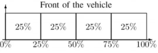
3.1 Campbell Model
The first model using energy net is related to K. Campbell (1974). It was based on the assumption that the absorbed deformational energy uniformly distributed on the whole width and height of the vehicle. Further assumption was that under low speed (4-5 km/h) the vehicle is able to tolerate the impact without deformation, and above this limit the deformation is almost linear.
Figure 1 The Campbell model
3.2 Röhlich Model
Figure 2 The Röhlich model
This model is a further development of Campbell’s model. The model doesn’t assume uniform distribution about the deformational energy along the width of the vehicle, but deal with a mathematical model based on crash-tests results. This method yields more accurate estimations, for example for the speed of the vehicle before the crash.
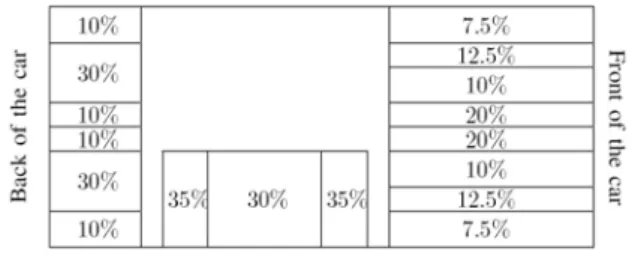
3.3 Schaper Model
The method worked out by Schaper based on the assumption that vehicles satisfying the prescriptions of FMVSS (Federal Motor Vehicle Safety Standards) have similar deformational characteristics. Using numerous crash-tests results few characteristic fields were defined in the car-body and the distribution of the absorbed deformational energy was examined in these regions.
Figure 3 The Schaper model
4 The Basic Concept
In the following we introduce the most important points of the suggested model [9] [10]. We assume having a 2 or 3 dimensional rectangular grid on the car body.
The most important thing which we have to know by a detailed analysis of the car body from the point of view of its deformation energy absorbing properties, is the inside structure of the car body. In most of the cases such detailed data about the car-body structure are not available, therefore it is proposed to approximate them from known discrete data. The introduced method is starting from the so-called energy cells. These energy cells are got by discretization of the car-body, to each of which a value for describing its energy absorbing properties is assigned. Other characteristic of these cells is, that each of them can absorb and transmit energy, which depends on the amount of the absorbed energy, e.g. as the stiffness property of a cell is changing during the deformation process proportionately to the absorbed energy. As higher the stiffness of the cells is, as more amount of energy is necessary to achieve the same rate of deformation.
4.1 Absorbing Functions
The energy absorbing property of a cell is not a constant value, but changes during the deformational process. Characteristically cells become saturated in a certain sense, so they are able to absorb less and less from the deformational energy.
Because of this the energy absorbing property is described by a monotone non–
increasing function, instead of a constant value. The simplest is the following piecewise linear function:
⎪⎩
⎪⎨
⎧
>
≤
− ≤
− <
=
b x
b x a
a x 0 1 )
( b a
x x b
f
Figure 4
Energy absorbing function and the absorbed energy: simple case
For better approximation one can take a convex linear combination of these kinds of functions:
) ( )
(
1
x f x
f
ni i i
∑
== λ
whereλ
i≥ 0
and∑
= n
=
i i
1
λ 1
If the input energy is E, then the absorbed energy is:
∫
=E
abs f x dx
E
0
) (
and the transmitted energy is
∫
− = −∫
=E E
trans f x dx E f x dx
E
0 0
) ( )
( 1
Figure 5
Energy absorbing function and the absorbed energy: convex combination
Principle of conservation of energy is fulfilled, so for absorbed and transmitted energy we have:Eabs+Etrans=E. Subsequently distribution of the transmitted energy between neighbours of the cell will play an important role.
4.2 Decomposition of the Impact
The deformational energy appears as kinetic energy (EES). According to this fact decomposition comes from the decomposition of the speed, according to a coordinate system with axes parallel with the grid applied on the car body. The orthogonal components of the velocity are vsinϕ and vcosϕ in two dimensional case, andvsinϑcosϕ, vsinϑsinϕ and vcosϑ in three dimensional case. So the decomposition of the deformational energy is:
• In case of 2D:Ecos2ϕ and Esin2ϕ
• In case of 3D:Esin2ϑcos2ϕ, Esin2ϑsin2ϕ and Ecos2ϑ
4.3 Direction Depending Properties
Deformational characteristics of the parts are depending on the direction of the outer impact: a certain part is easy to deform in a certain direction and sometimes very difficult (demands more energy) to deform in other direction (esp. orthogonal direction). Because of this it seems practical to assign different absorbing functions to different orthogonal directions.
Using decomposition in the following we deal with outer impacts parallel with one of the axis of the grid. The final energy distribution will be the sum of the partial energy distributions got by computing with components of the outer impact.
5 Deformational Models
We could distinguish at least two models, according to what happens with the transmitted energy. If the transmitted energy is the input of the following cell in the ‘tube’ then we get a simple model (1st order model). In some cases it gives a right approximation, but in other cases we should determine weighted interconnections between the neighbouring cells (2nd order model).
Figure 6
Schematic map of the deformation for the first and second order models
5.1 First Order Model
In this case the energy transmitted by the cells is assumed spreading in the direction of the original impact (as we mentioned above, we think of a component of the decomposed impact). It means that forces (screwing forces) between neighbouring cells are ignored; a cell can’t deform or drag its neighbours. One can imagine this case as the deformational energy spreads in parallel, but independent
’tubes’ along the car-body. This model can be applied cases in which the crash takes place in the whole width of the vehicle (frontal crash), but doesn’t give satisfying result for partially overlapping crashes (for instance bumping against a tree).
Figure 7
Energy transmission: first order model
5.2 Second Order Model
For applications, modelling of the energy spreading process between neighbouring cells not only in the direction of the original impact, but in orthogonal directions, is very important. A possible solution for this task is if we assume that the
transmitted energy is distributed in a certain proportion between all of the neighbours (but usually the next in the ’tube’ get the most of the energy).
Let’s see the following example. The crash meets the edge of the vehicle (for instance bumping against a pole), and then the deformational energy spreads from here into each directions (see Fig. 8). In the upper row every cell give the si1times of the transmitted energy to the next cell, and si2 times to the cell bellow (in real beside). The latter case models the energy spreading caused by internal forces between the cells. The energy from this process is interpreted as result of an impact parallel with the original, so we deal with absorbing functions assigned to this direction. In the upper row the inputs are computed similar to the first order model, but in this case we calculate with the si1times of the transmitted energy.
There is a difference in the lower row: the input of cell (2, 1) is s12 times of the output of cell (1, 1), and the output is distributed between different directions (p11, p12). Here we assume that there is no reaction: there is no energy transmission from the lower row to the upper. The input of cell (2, 2) is the sum of p11times of the output of cell (2, 1) and s22times of the output of cell (1, 2). In general, the input of cell (2, i) is the sum of pi−1,1times of the output of cell (2, i − 1) and si,2
times of the output of cell (1, i). The 3rd, 4th . . . row can be computed in a similar way.
In general, the computational method is the following:
1 Determine the absorbed and transmitted energy in the first row.
2 Determine the absorbed and transmitted energy at the first element of the second, third ... row applying the input energy assigned to the first element of the second row.
3 Determine the energy transmitted by cell (2, 2) with the sum of its inputs.
4 Using this result determine the same for the third, fourth ... row.
5 Execute the procedure on the whole cell matrix.
Figure 8
Energy transmission: second order model
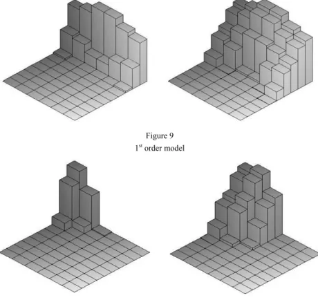
6 Illustrative Examples
In this section we show some examples for models introduced in the previous section. There are 6×10 cells in the model, but the parameters of the absorbing functions and the parameters describing the interactions between the cells are not real, just for the demonstration. In both of the cases we show two snapshots, with lower and higher input energy.
Figure 9 1st order model
Figure 10 2nd order model
Conclusions
A new theoretical approach was introduced for describing the changing of the energy distribution during the whole deformational process of the vehicle body.
As can be seen from the simulation results, applying this treatment more sophisticated estimations can be made than with using the preliminary methods.
The crucial point of the suggested method is the right determination or estimation of the parameters of the absorbing functions. This problem can be solved by analysing crash test results, crash data, digital photos and digital sequences with human experts and intelligent expert systems.
Acknowledgement
This work was supported by the Hungarian National Science Research Found (OTKA) under grants T048756 and T042896.
References
[1] A. Rövid, A. R. Várkonyi-Kóczy, P. Várlaki, P. Michelberger: Soft Computing Based Car Body Deformation and EES Determination for Car Crash Analysis, In Proceedings of the Instrumentation and Measurement Technology Conference IMTC/2004, Como, Italy, 18-20 May, 2004 [2] A. Rövid, A. R. Várkonyi-Kóczy, P. Várlaki: Intelligent Methods for Car
Deformation Modeling and Crash Speed Estimation, In Proceedings of the 1st Romanian-Hungarian Joint Symposium on Applied Computational Intelligence, Timisoara, Romania, May 25-26, 2004
[3] A. R. Várkonyi-Kóczy, P. Baranyi, Soft Computing Based Modeling of Nonlinear Systems, 1st Hungarian-Korean Symposium on Soft Computing and Computational Intelligence, Budapest, Hungary, Oct. 2-4, 2002, pp.
139-148
[4] G. Molnárka: On the Buckling of a Viscoelastic Rood, Numerical Analysis and Mathematical Modeling Banach Center Publications,Warsaw, Poland, 1990, Vol. 24, pp. 551-555
[5] H. Steffan, B. C. Geigl, A. Moser, H. Hoschopf: Comparison of 10 to 100 km/h Rigid Barrier Impacts, Paper No. 98-S3-P-12
[6] P. Griškevičius, A. Žiliukas: The Crash Energy Absorption of Vehicles Front Structures, Transport Vol. 18, No. 2, 2003, pp. 97-101
[7] T. Péter: Reduction of Parameters of Spatial Nonlinear Vehicle Swinging Systems, for Identification and Purposes, Periodica Polytechnica, Vol. 36, No. 1, 1992, pp. 131-141
[8] T. Péter, E. Zibolen: Model Analysis in Vehicle Dynamics in Computer Algebraic Environment, Symposium on Euroconform Complex Pretraining of Specialists in Road Transport, Budapest, June 9-15, 2001, pp. 319- 331 [9] I. Harmati, P. Várlaki: Estimation of Energy Distribution for Car-Body
Deformation, In. Proc. of the 3rd International Symposium on Computational Intelligence and Intelligent Informatics, March 28-30, 2007, Agadir, Morocco
[10] I. Harmati, A. Rövid, P. Várlaki: Energy Absorption Modelling Technique for Car Body Deformation, In Proc. of the 4th International Symposium on Applied Computational Intelligence and Informatics, Timisoara, Romania, May 17-18, 2007, pp. 269-272
[11] E. Halbritter, G. Molnárka: Simulation of Upsetting. Proc. of the 10th International DAAAM Symposium, Vienna University of Technology, October 21-22, 1999. L, R.