element method
Laszlo Porkolab
pand Istvan Lakatos
Department of Road and Rail Vehicles, Faculty of Mechanical Engineering, Informatics and Electrical Engineering, Szechenyi Istvan University, Egyetem ter 1, H-9026 Gy}or, Hungary
Received: November 25, 2020 • Revised manuscript received: January 18, 2021 • Accepted: January 19, 2021 Published online: May 3, 2021
ABSTRACT
Crash tests of vehicles are specified by government programs. This laws are includes only minimum requirements for individual components. Therefore additional consumer protection load cases have been developed by independent private institutes. Finite element method simulations can reduce development periods and the number of cost-intensive real crash tests. The goals of the calculations are that the early detection of component failure, the protection of occupants or pedestrians. The biggest challenge of the future, in the field of vehicle occupant safety is the interaction of the airbags and belt system with dummy by the electric vehicles, which have the concept of autonomous driving function.
The aim of the research is to investigate this area using a simulation model.
KEYWORDS
crash test, occupant safety, finite element method, electric vehicles, autonomous driving
1. INTRODUCTION
In recent time, the issue of occupant safety has become more and more important in the automotive industry. Customers are also consciously monitoring the value of a given model in the crash test, how many airbags as a standard equipped the car and how safe the car is. As a result of the specified government vehicles safety programs, the vehicle occupants more likely will survive moderate and severe crashes. The latest accident statistics show that tremendous progress has been made to protect occupants.
Nowadays, the unstoppable rise of electric cars is becoming more and more noticeable.
An electric car in the same category behaves differently in a crash test than a car equipped with an internal combustion engine. There are several differences, but one of the most obvious is that the passenger cell in the electric car has no rigid block like in the internal combustion variant, which only minimally capable of deformation.
Another trend can also be observed at large automotive industry companies, which would lead the future towards autonomous, self-driving cars. A self-driving car raises a number of questions from a vehicle safety perspective. While the car is driving itself, occupants can move and talk freely, so in the event of a crash, the car’s passive pro- tection system, seat belt and airbags must be able to protect occupants in this situation as well.
The research problem is therefore the passive safety of the occupants in a fully self- driving car. What are the new possibilities for airbag deployment for self-driving vehicles?
In a vehicle without a steering wheel, airbags to protect the driver will be conceivable in a radically new position, size and shape. Another research problem is the extent to which the seating position of passengers in the event of a crash affects their injuries in the event of a crash. Therefore, the effect of non-conventional seating positions on the extent of injuries, from the case of a rotated driver’s seat to the case of a fully reclined driver’s seat, must be examined.
Pollack Periodica • An International Journal for Engineering and Information Sciences
16 (2021) 2, 30–35
DOI:
10.1556/606.2021.00306
© 2021 The Author(s)
ORIGINAL RESEARCH PAPER
pCorresponding author.
E-mail:porkolab.laszlo@sze.hu
2. LAWS AND CONSUMER PROTECTION REQUIREMENTS FOR VEHICLE OCCUPANT SAFETY
2.1. Crash-regulations in United States and in Europe
Crash tests of vehicles are specified by Government programs for instance North America Federal Motor Vehicle Safety Standards (FMVSS) or in Europe the Economic Commission for Europe (ECE) regulations. The laws are included only minimum requirements for individual components therefore additional consumer protection load cases have been developed by inde- pendent private institutes. The New Car Assessment Program (NCAP) institutes and the Insurance Institute for Highway Safety (IIHS) are among the most important organizations.
InFig. 1the most important types of crash tests can be seen. Vehicles have to comply with a wide range of requirements from all directions. The most important areas are frontal and side impact. But there are also many other areas like steering wheel or the other interior investigations (with door, seat belt, seat and so on).
2.2. Europa – new car assessment program
Euro-NCAP contains two front-crashes and also two side- crashes and a pedestrian crashes. The front-crashes are shown on the left side inFig. 2,firstly the full width frontal crash with 50 km/h 08100% overlap. In this case, hybrid III 50% dummy sits on the driver side and hybrid III 5%
dummy on the passenger’s side. The hybrid III 50th male crash test dummy is the most widely used crash test dummy in the world for the evaluation of automotive safety restraint system in frontal crash testing. 50% is a male 5% is a female dummy [1, 2]. Below is the offset frontal crash with 64 km/h 0840%. In this case, hybrid III 50% dummy sits on the driver side and hybrid III 5% dummy on the passenger’s side.
Euro-NCAP will change this crash test in the future, this new test called Mobile Progressive Deformable Barrier (MPDB) test, in this test the test car is driven at 50 km/h and with 50 percent overlap into a deformable barrier mounted on an oncoming 1,400 kg trolley, also traveling at 50 km/h.
The barrier represents the front end of another vehicle, getting progressively stiffer the more it is deformed. The test replicates a crash between the test vehicle and a typical mid- size family car [3].
In the middle inFig. 2the two side-crashes can be seen, above the barrier side crash test with 50 km/h 90 with 950 kg Mobile Deformable Barrier (MDB) trolley. In this case, ES-2 dummy sits on the driver side. Below is the pole side crash test with 32 km/h 758against the 254 mm pole, in this case the word sid 50% dummy sits on the driver side. And is shown at the bottom right of the slide the pedestrian crash test, those are leg and head impacts with 40 km/h.
Euro-NCAP included also active safety regulations.
Active safety means that all safety systems are active prior to an accident (for example Anti-lock Braking Systems (ABS), Electronic Stability Control (ESC), Tire Pressure Monitoring System (TPMS), Lane Departure Warning System (LDWS), Adaptive Cruise Control (ACC), Driver Monitoring System (DMS), Blind Spot Detection (BSD) and Night Vision System (NVS)). Passive safety means that all components of the Fig. 1.Crash-regulations
(Source:Author's plot)
Fig. 2.Euro-NCAP crash tests (Source:Author's plot)
vehicle (primarily airbags, seat-belts and the physical struc- ture of the vehicle) help to protect occupants during a crash.
3. THE IMPACT OF OCCUPANT SAFETY ON THE INTERIOR AND EXTERIOR OF VEHICLES
InFig. 3few examples for how occupant safety influences the interiors and exteriors of the vehicles can be seen. Thefigure on the left shows the possible areas for exterior changes. The most important thing here is to protect pedestrians and meet the requirements of a side collision. The images on the right show the interior change areas. There can be seen that the steering wheel is often reworked for vehicle safety requirements due to the driver airbag module. On the pas- senger side, the instrument panel geometry may change due to the passenger airbag module. The area of the lower instrument panel shall provide for the possibility of parallel contact of the knees on the instrument panel in accordance with the front crash requirements. The center console also often requires modifications due to side accident regulations [4].
The purpose of occupant safety development is to reduce the severity of injuries. Analysis of injury symptoms shows that head, neck, chest, abdomen, and leg injuries are the most common and long-lasting in terms of recovery for different types of accidents. A modern car is also equipped with driver and passenger airbags, side airbags, head and knee airbags. In addition, where the head may be struck, permanent damage to the head can be avoided by proper design, foam upholstery or deformation elements. Similarly, to prevent foot injuries, deformation elements can be formed in the instrument panel that are able to absorb the bulk of the energy [5].
The seat belt is the most important restraint system because it is in direct contact with the occupant and prevents the contact of the upper extremities with the vehicle interior and this reduces the severity of the injury. The seat belt was one of the very first safety devices in cars, first with two points, which fastened the passenger at two points on either side of the waist, and then the traditional three-point belt spread. The third point of the three-point belt is attached to the top of the car body and is it already able to hold the shoulders. Another occupant protection system is the airbag.
The air cushion is inflated explosively and intercepts the occupant. Not to be ignored is the restraint effect achieved by the airbag. It is important that the airbag can only provide adequate protection with a seat belt together for a passenger.
4. OCCUPANT SAFETY SIMULATION
4.1. Finite element method in general and the necessary components
Finite Element Method (FEM) simulations can reduce development periods and the time-to-market for a product.
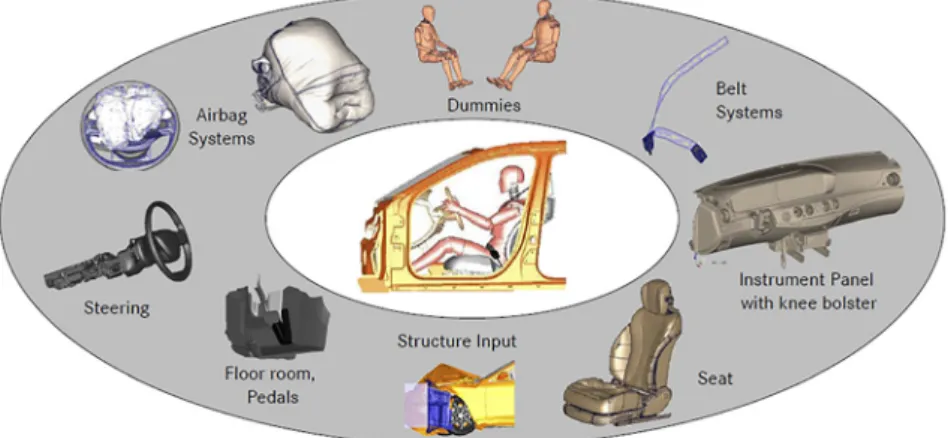
The goals of the calculations are the early detection of component failure, the protection of occupants or pedes- trians and the reduction of cost-intensive real crash tests. In Fig. 4the most important components, which are necessary to make a simulation can be seen, these are all interior components like dashboard, seats, seatbelts, steering column and steering wheel, airbags of course, foot-well, the pedals and of course the dummys.
The finite element method is a numerical method for the approximate solution of partial differential equations. The finite element method is not suitable for manual calculations, as a lot of elementary operations would have to be solved for it. However, today’s high-performance personal computers are capable of solving a number of important tasks. Not only the solution of the actual mathematical problem (solution of the system of equations, eigenvalue problem) is labor- intensive, but also the preparation of the data itself and the evaluation of the results take a lot of time. Therefore, a preprocessor and a postprocessor are part of modern com- puter programs. Based on the Computer Aided Design (CAD) model, the preprocessor automatically generates the finite element mesh with human correction and post-pro- cessing. The postprocessor helps visualize the results [6, 7].
In this research LS-DYNA professionally finite element solution program, supplemented with ANSA preprocessor and Animator postprocessor program are used. As a starting point, a complete vehicle model is used that is available free and includes all important components (body, dashboard, seat, seat belt, dummy, etc.). This basic model will be further developed [8, 9].
Fig. 3.Examples how can occupant safety influence the interior and exterior design (Source: Author's plot)
4.2. Types of airbags
InFig. 5the most common types of airbags can be seen. On the left side above is the driver airbag which is usually be- tween 45 and 60 L, Time To Fire (TTF) is usually between 10 and 20 ms. At this moment the airbag starts to open, 0 ms means the moment when the signal come from the crash sensor [8]. On the right side above is the passenger airbag which is usually between 80 and 130 L so is it much bigger than a driver airbag, TTF is usually between 20 and 30 ms, so starts about 10 ms later than a driver airbag.
Frontal airbags have been standard equipment in all pas- senger cars since model year 1998. Many new cars have a weight sensor for the front passenger seat that will prevent the airbag from deploying if a small child is sitting there. For older cars without a weight sensor, the airbag’s force can cause injury in younger children, so the government sug- gests that children under 13 should ride in the back seat. On the left side down is the head and side airbag, which are usually between 15 and 20 L, TTF is usually between 5 and 10 ms. On the right side down is the knee airbag, which is usually between 15 and 20 L, TTF is usually between 10 and 20 ms [10].
4.3. Dummy kinematic during a crash
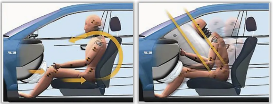
InFig. 6the dummy kinematics during a crash can be seen. The whole dummy moves forward then the seat belt brakes further forward movement of the pelvis at the same time the knees come into the contact with the dashboard and the upper body rotated forward and down [11]. The primary goal of course, is to avoid head contact with the steering wheel or the dashboard on the driver’s and passenger’s side, airbags can help with this.
The simulation goals are optimize the size of the airbags and the restraining force effect of the seat belt that the distance of the head remains at least 50 mm from the interior components.
5. FUTURE CHALLENGES FOR OCCUPANT SAFETY
5.1. Generally challenges
The biggest challenge of the future is the interaction of airbags and belt system with dummy by the electric vehicles what has the concept of autonomous driving function. There are new opportunities to build airbags for self-driving Fig. 4.Occupant safety simulation components
(Source: Author's plot)
Fig. 5.Types of airbags (Source: Author's plot)
vehicles. In a vehicle without a steering wheel, airbags to protect the driver will be possible in a radically new position, size and shape [12]. Another research problem is the extent to which the seating position of occupants affects their injuries in the event of an accident, while cars typically have their seats facing one way. Self-driving vehicle system could potentially allow all of the seats to face the middle of the vehicle, as if it is a room and everyone is able to talk to each other. Along with the airbags, it is possibility of passengers colliding with each other if facing each other in a collision.
With a reverse-mounted front seat and a conventional rear seat, an impact at the front could force the rear passenger into contact with the front passenger’s feet or knees.
5.2. Non-traditional seating positions
The research examines the impact of non-traditional seating on injury rates, from the case of a rotated driver’s seat to the case of a fully reclined seat. InFig. 7the cases, which research focuses, these are 08, 308, 608, 908, 1358and 1808can be seen.
6. CONCLUSION
It has been noticeable since 1970 that the number of deaths from vehicle accidents has been falling. Due to the steadily stricter requirements in regard of the legal and consumer protection requirements, several improvement and studies in the area of occupant protection have been carried out.
Nowadays, the transition from conventional driving to full
automation of driving is in an advanced phase. As a result of this development, the driver in an autonomous vehicle only finds himself as a passenger. The requirements for the seating position of the occupant will also change. The typical upright and straight sitting position is no longer absolutely necessary and desirable for reasons of comfort.
The development of driverless vehicles by the automotive industry is changing driving behavior. The driver becomes a passenger and can perform activities and no longer need to pay attention to controlling the vehicle. Thanks to the freedom gained, it is no longer necessary for the driver to remain in an upright sitting position facing straight ahead.
An important research direction can be the influence of a rotating seat in the first row of seats in a car on future re- straint system is shown.
The aim of the research is to build a computer simulation model that can be used to investigate the new possibilities of airbag placements in a self-driving vehicle. In a vehicle without a steering wheel, an airbag to protect the driver will be conceivable in a radically new position, size and shape, all three options to be considered. Relying on the constructed simulation model, the next phase of the research can reveal the effect of non-traditional seating positions of a self-driving vehicle, from the case of a rotated driver’s seat to the case of a fully reclined driver’s seat.
REFERENCES
[1] K. Fung, R. Xu, S. Jung, and J. Sobanjo,“Development and testing of a simplifed dummy for frontal crash,” Exp. Tech., vol. 43, pp. 7–14, 2019.
[2] Y. Kurano, K. Hikida, S. Hibara, Y. Kawamura, K. Maehara, and T. Narukawa, “Two-dimensional degenerated model of next- generation crash test dummy THOR 5F,” Int. J. Automot. Eng., vol. 11, no. 3, pp. 94–100, 2020.
[3] A. Kullgren, A. Lie, and C. Tingvall,“Comparison between Euro NCAP test results and real-world crash data,”Traffic Inj. Prev., vol. 11, pp. 587–593, 2010.
[4] R. Setiawan and M. R. Salim, “Crashworthiness design for an electric city car against side pole impact,”J. Eng. Technol. Sci., vol.
49, no. 5, pp. 587–603, 2017.
Fig. 6.Dummy kinematic during a crash (Source:Author's plot)
Fig. 7.Different non-traditional seating positions (Source:Author's plot)
[5] W. M. Choi and H. Y. Jeong,“Design methodology to reduce the chest deflection in us ncap and euro ncap tests,”Int. J. Automot.
Technol., vol. 13, pp. 765–773, 2012.
[6] J. S. Wright, and L. M. Hughes,Computer Animation. Nova Sci- ence Pub. Inc. England, 2011.
[7] P. Ivanyi,“Parallel conversion offinite element meshes,”Pollack Period., vol. 9, no. 3, pp. 89–102, 2014.
[8] J. O. Hallquist, LS-DYNA R Theory Manual. Livermore, CA:
Livermore Software Technology Corporation, 2006.
[9] P. Ivanyi,“Numerical investigation of the pullout phenomenon of a bolt from a steel plate,”Pollack Period., vol. 3, no. 2, pp. 35–50, 2007.
[10] C. R. Bass, J. R. Crandall, J. R. Bolton, W. D. Pilkey, N. Khaewpong, and E. Sun,“Deployment of air bags into the thorax of an out-of-position dummy,”SAE Tech. Paper, Paper no. 1999-01-0764, pp. 1–17, 1999.
[11] D. Poulard, Q. Zhang, J. R. Cochran, B. Gepner, and J. Kerrigan,
“Quantitative evaluation of the occupant kinematic response of the THUMS 50TH-percentile male model relative to PMHS lab- oratory rollover tests,”Traffic Inj. Prev., vol. 17, Supplement 1, pp. 101–108, 2016.
[12] K. Golowko, V. Zimmermann, and D. Zimmer, “Automated driving influences on the restraint system,” (in German) ATZ- Automobiltechnische Z., vol. 119, pp. 26–33, 2017.
Open Access. This is an open-access article distributed under the terms of the Creative Commons Attribution 4.0 International License (https://creativecommons.org/
licenses/by/4.0/), which permits unrestricted use, distribution, and reproduction in any medium, provided the original author and source are credited, a link to the CC License is provided, and changes–if any–are indicated. (SID_1)