Control of LED Lighting Equipment with Robustness Elements
Alexander Baklanov, Svetlana Grigoryeva
D. Serikbayev East Kazakhstan State Technical University Faculty of Information Technology and Power Engineering A. K. Protazanov Str. 69, 070004, Ust-Kamenogorsk, Kazakhstan e-mail: {ABaklanov, SGrigorieva}@ektu.kz
György Györök
Óbuda University, Alba Regia Technical Faculty Budai út 45, H-8000 Székesfehérvár, Hungary gyorok.gyorgy@amk.uni-obuda.hu
Abstract: This paper presents the results of the study into the control of light-emitting-diode lighting equipment. It also deals with the issues of robustness in the organization of controlling key parameters of a lighting system. An experimental facility for research of using high-power LEDs and controlling them with compensation of uncertainties was developed. The results of that development allows for showing the effectiveness of the use of additional control loops with elements of robust control. Additionaly, there are suggestions to improve systems both of indoor and outdoor led lighting devices of increased power.
Keywords: robustness; high power LED; control system; controller; Peltier element;
SCADA system
1 Introduction
Modern control systems are characterized by a high degree of complexity of a control object resulting from the incomplete priori information about, object parameters, properties of external acting disturbances and the presence of non- stationary and nonlinear dynamic characteristics of the object.
Classical methods of synthesis of control systems assume that the object and controller models are known, and have constant parameters. However, the model of a real physical system will always be inaccurate for the following reasons:
change of parameters due to certain circumstances; dynamic properties not included in the model; time lag not accounted for; change of the operating point location; sensor background noise and unpredictable external disturbances.
The development of electronic engineering requires development of reliable electronic systems that are implemented by way of expanding adaptivity to external and internal factors. The development of systems with a high degree of adaptation can be implemented with the use of robust control, i.e. control with a certain margin of stability.
The problem of adaptive and robust control under restrictions of external and internal uncertainties is a major issue in modern control theory. The most common methods of robust control are based on the use of regulators that ensure a certain stability margin of the closed-loop system [1, 2], various types of observers [3, 4], etc. One of the effective ways of controlling uncertain objects is through compensation of disturbances. The problem of compensating for uncontrolled disturbances is discussed in a series of papers [5, 6, 7, 8], in which various schemes of control systems architecture are considered.
2 Application of the Theory of robustness in Electronic Control Systems
In a general case a synthesized (according to the criteria of the sustainability) control system may have either a low sensitivity to changes of parameters of a control object or, conversely, a greater one. In the first case we speak of the system structural or its robustness, while in the second case, the system is almost inoperative as the slightest parameter drift leads to the loss of stability. The implementation of such systems is based on designing an electronic circuit which allows for maintaining the efficiency of the whole control system provided there are uncertainties in its description [9, 10].
The general diagram of the electronic system of controlling with uncertainties associated with the internal and external factors is shown in Figure 1. The internal factors include errors connected with the operation of the circuit, changing parameters of circuit components, engineering errors, errors in the firmware of the scheme, the increase in internal noise, etc. External factors include environmental influences and human errors related to improper operation of the electronic system, high ambient temperature and exposure to different radio waves and other types of electromagnetic radiation. The interaction of control systems with parameter change uncertainties is carried out by means of tracking system performance errors and controlling the correct operation of each element of the system.
Figure 1
An overall view of the electronic control system with account for external and internal uncertainties The system shown in Figure 1, may be presented by a general scheme describing robust control systems in Figure 2 [11], where P is the nominal control system; C is the synthesized controller; ∆ is the set of all possible uncertainties in the description of the system; w is the vector of a signal including noises, disturbances and reference signals (external input of the system); z is the vector of the signal including controlled signals and tracking errors (the system output); u is the control signal, and y is the monitor signal; the signals η and v are uncertainty input and output respectively.
Figure 2
General scheme of a robust control system
The papers [12, 13, 14] investigate the robust control system using different architectures of control circuits. Let us consider a system with a parallel architecture of robust control.
Figure 3 presents the diagram of a system with robust control based on the parallel architecture of monitoring and control. System input w(t) includes the reference signal and all the sum signals of noise and interference of the whole system. The output signal z(t) includes the monitored signal and the tracking error signal. The uncertainty system ∆n is supplied by the contours of processing and controlling input signals vn(t) and output ηn(t) control signals. This system allows implementing robust control on account of compensating for uncertainties and thereby increases the stability of the system in the optimal mode. In other words, it extends the control range of the overall system. This scheme has a parallel architecture and allows for controlling the compensation of uncertainties independently.
Figure 3
The control system based on the parallel architecture
In the implementation of schemes of LED lighting automatic control there are both external and internal perturbing factors (uncertainties) affecting the quality of lighting and the operation time of a lighting device. For example, the current oscillations lead to scintillation and degradation of the crystal associated with the current instability within the crystal [15]. The increase of the temperature of the crystal also leads to the loss of optical power of the LED and at the end, to its complete degradation [16].
In real LED lighting systems these factors do not allow for ensuring, specified by the manufacturer, resources of 50 thousand hours of continuous operation with retention of the original optical characteristics.
In real conditions of premise lighting there is an additional light bias associated with natural light. At that this illumination may change over time within a significant range, and also have unpredictable, fast changing light conditions changes. Taking into account that the external natural light can improve the stability of the automated system and provide the required light level.
3 Description of the LED Lighting System Regulation Scheme
In order to implement an automation system which takes into account the above listed uncertainties there was developed the scheme [17] shown in Figure 4. Due to the first control loop this scheme maintains the desired temperature of the LED crystal. The second control loop provides the necessary light intensity due to changes of the driver operation modes.
Let us consider the operational procedure for this scheme. The first control loop maintains the desired temperature in the range which provides stable performance of the LED 4, and ensures its non-degradable operation within the asserted according to the manufacturing company period of time. The adjustment is carried out automatically by modifying the operating voltage of Peltier element 3 with the help of the designed power source 2. A thermally sensitive resistor 5 serves as the temperature sensor.
The second regulation loop provides a constant level of light intensity by controlling the LED 4 power by using the PWM regulation of driver 1. The operation of the driver is controlled by a STM32 microcontroller. A monitor signal for control is transmitted from the photoresistor 6 to the controller 7 which executes the program with the necessary LED operational scenario. The control of sunlight is carried out by using the photoresistor10. The signal from the photoresistor enters the analog input of the microcontroller and allows for maintaining the total light intensity of the premises constantly. This loop provides compensation of the natural light, as well as taking into account the combined illumination of the working area.
The disturbances associated with LED current changes can be controlled using the analog input of the controller and are displayed on the personal computer monitor screen. The signal of the current related uncertainty compensation is obtained by inverting the input signal and is added to the LED driver 1 control signal.
To ensure the operation of the lighting system only in the presence of people the motion sensor 8 is used. The signal from the sensor is communicated to the controller and provides enabling or disabling the system depending on the presence of people. The recording of the intelligent system algorithm of the microcontroller operation is carried out by a personal computer 9 with the necessary software.
1 – LED control driver; 2– the power source of the Peltier element temperature control; 3 – Peltier element; 4 – LED; 5 – thermally sensitive resistor; 6, 10 – photoresistor; 7 – STM32 microcontroller; 8
– motion sensor; 9 – PC with the intelligent control software Figure4
The LED lighting system regulation scheme
The study of this system operation (Figure 4) may be performed using a structural diagram shown in Figure 5. This diagram shows the three control loops for optimum operation of a lighting device (an object of control P(s)), while the main control loop provides regulation of the light intensity level due to the controller C1(s) (LED driver) control. The instabilities of temperature occurring in the system are monitored by the temperature sensor HT(s) and controlled by the controller C2(s) based on the use of the Peltier plate. The current fluctuations present in the system are compensated using the controller C1(s).
Figure 5
Block diagram of the automated control system for the LED lighting system
To ensure that robust control is implemented using the principles of parallel architecture (Figure 3) the discussed above block diagram (Figure 5) can be transformed into a system of control with elements of robustness (Figure 6). The changes in temperature, current and light intensity can be represented in the form of uncertainties, i.e. not predicted changes.
Figure 6
The robust control of a lighting system using LEDs
The following block diagram shows the system with the compensation for uncertainties vТ(t), vI(t), vE(t), the uncertainties of the temperature, current and light intensity respectively. With a robust control the compensation for uncertainties irrespective of the main control loop is controlled by controller C1(s).
The output signals of the uncertainties ηI(t), ηE(t), ηT(t) are necessary for controlling compensation. The information about the compensation quality is obtained by comparing the input signal vi(t) to the output signal ηi(t).
The compensation for the temperature uncertainty controlled by sensor HT(s), is performed on account of maintaining a constant temperature of the LED crystal with the help of the controller C2(s).
The disturbances associated with current and light intensity are eliminated by using controller C1(s) where the disturbance signals coming from sensors HI(s) and HE(s) are summed. Thanks to this, the LED lighting control stabilization system becomes more stable. This allows maintaining an operating life of the LED crystal and, as a consequence, increasing the operation time of both the LED and the system as a whole.
It is shown in Figure 7 the model made in program Simulink of bypass of robust control LED element, compensating thermal uncertainty.
Figure 7
The model of robust control LED element
The voltage control loop is selected on the Peltier element to calculate the local automatic control system. Where there is temperature sensing of the LED. The temperature should be maintained at a level of 400C. The resulting transition process is shown in Figure 8.
In the absence of voltage the Peltier element LED is heated to 850C for 40 seconds. This process exceeds the optimum temperature of the LED operation.
After applying voltage to the Peltier element the LED returns to normal operating mode with the corresponding nominal temperature of 400C for 60 seconds, at the same time the voltage at the Peltier element corresponds to 4.5 V (Figure 12).
Figure 8
Graph of the transition process in the system of automatic regulation of the LED temperature
4 Description of the Experimental Unit
For the study of automated control system for a LED lighting device we developed an experimental unit with elements of robustness (Figure 9).
Figure 9
General view of the experimental unit for the LED automated control
It consists of two blocks: Block 1 – a lighting module, which is a cased LED with a light intensity sensor. Position 1 in Figure 9 shows the lower part of the housing;
Block 2 – the LED controller and power elements and the Peltier plates (Figure 9, Position 2).
Communication between the blocks is carried out by means of the RS32 bus, Block 2 also has a connection to the PC through the USB port. There is SCADA system TRACE MODE 6 installed on the host PC; it is supplied with a specially developed application for monitoring the controller, receiving data from it and adding them to the archive using the ACCESS database management system.
The lighting module consists of a light-tight box where the following are installed:
the Nichia NСSL219B LED [18], the system of supporting the LED crystal necessary temperature, the light intensity control system, and a source of additional lighting.
The LED is mounted on an aluminum plate along with the temperature sensor for the crystal temperature control. The plate is mounted to one side of the Peltier element through an organic-silicon heat-conducting paste with the aid of spring clips. To the other side of the element, with the help of organic-silicon heat- conducting paste, there is mounted a massive heat sink with a fan for removing or applying heat, depending on the function of heating or cooling, respectively. The temperature sensor placed on the radiator is necessary to prevent overheating of the Peltier element. This design is shown in Figure 10.
1 – LED; 2, 5 – aluminum plate; 3 – temperature sensors; 4 – Peltierplate; 6 – copper radiator; 7 – fan Figure 10
The LED crystal temperature demonstrating construction
Across the LED, on its axis, there is a light intensity sensor – a calibrated light meter that measures the total luminous density from an artificial (tested) and a natural lighting source. To simulate natural lighting we used an additional LED mounted in the casing and powered from the IT-300 power source.
The controller module is functionally composed of the main board on a 32-bit microprocessor ARM Cortex M4 STM32F401 [19] connected to the LED control block and the heater control block (Figure 11).
This microcontroller performs measurement processes of the feedback signal and the calculation of the manipulated variable according to the algorithm of PID- regulator operating. The feedback signal from the temperature sensor is fed to an analog-digital converter of the microcontroller. Selection of PID coefficients was carried out by successive changes in these factors and measuring the response of the system with their values. Thus, we have the system response to external factors, shown in Figure 14.
1 –controller block; 2 – heater control block; 3 – LED control block Figure 11
The exterior appearance of the controller board and the blocks of controlling the LED The LED control block regulates the LED current depending on the task, monitors the temperature of the crystal, measures light density and sends data to the controller main board. The heater control block controls the LED crystal temperature using the Peltier element, controls the radiator temperature, and controls the air flow fan. The heater control block is connected to the main board in the same way as the LED control block. The main controller board receives data from the LED control block and the heater control block. On the basis of these parameters it controls the LED current and temperature regulators, sends the data to the SCADA system via USB for archiving and further processing.
To control the operation of the whole system we developed the software the interface of which is shown in Figure 12.
In real-time the interface switches to the working mode which shows the ongoing processes (Figure 13). This interface shows the behavior of temperature and light intensity (temperature – Line 1, light intensity –Line 2, power – Line3).
Figure 12
The main window of the custom application
Figure 13
Dialog box of the analysis of LED characteristics through time
5 Results of the Experiment
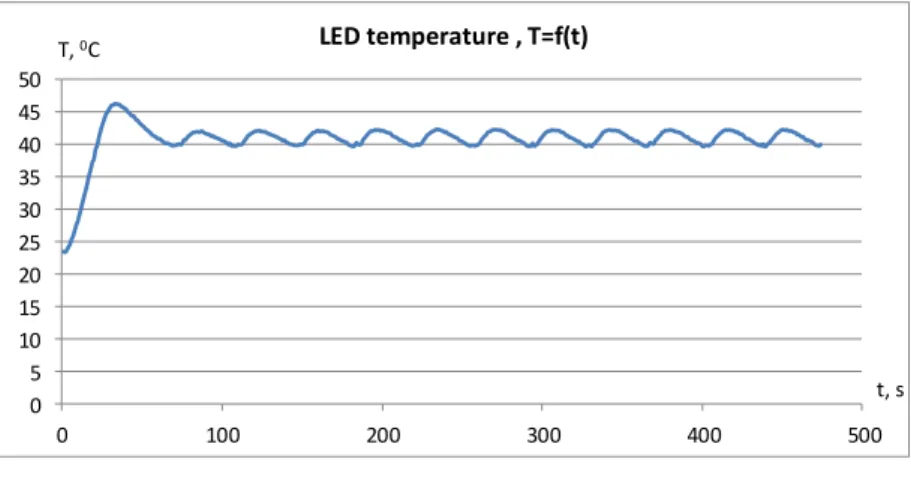
As a result of the study of the LEDs operational modes it was found that such a control system with compensation for temperature and current uncertainties (using robustness) makes it possible to obtain a stable operation mode (in a wide range of changes in the environment parameters) of a LED at the temperature of 400C. This mode allows for eliminating the degradation of the LED matrix, and providing the highest light intensity values.
Figure 14 shows the transient process of setting a certain temperature with the help of the developed automation system, i.e. it actually shows the additional control loop that ensures the robustness of the system. The parameters were taken at LED I = 350 mA, LED T = 400C.
0 5 10 15 20 25 30 35 40 45 50
0 100 200 300 400 500
T, 0С
t, s LED temperature , T=f(t)
Figure 14
Transient process of temperature setting with the help of the designed system of regulation When the temperature stabilizes (the uncertainty of temperature fluctuation is eliminated) the output power of LEDs has a more stable character. The power does not change through time, either upward or downward. The only change in the power is associated with the white noise at the output of a stabilized power supply.
This dependence of the power on time is shown in Figure 15. The parameters were taken at LED I = 350 mA , LED T = 400C.
500 600 700 800 900 1000 1100 1200 1300 1400 1500
0 100 200 300 400 500
P, mW
t, s LED power, P=f(t)
Figure 15
Dependence of the LED power on time at the stabilized temperature
Despite the fact that there is a main power control loop at significant temperature changes that occurs under natural conditions of lighting device exploitation, the control range is not enough to support the target power. As stated above in our case, using a robust approach (maintaining constant LED crystal temperature), we obtain stabilized power during the LED long-term exploitation.
Conclusion
The results of the experiment showed that the use of current approaches to control complex systems allows ensuring the stability of system operational modes. In this case, using the theory of robustness and on this basis creating additional control loops led to eliminating the factors that negatively affect the operation of the system. On this account the system, as seen in Figures 14, 15, becomes more stable and provides long-term stable operation of high power lighting LEDs. The application of proposed method for high power lighting equipment will significantly increase its service life, and also help to avoid degradation of LED crystals. The lighting equipment can be used for multiple purposes: in offices, industrial premises and for outdoor lighting.
This technique eliminates both external and internal uncertainties, adding the control loops in accordance with the robust approach (Figure 3). The further development of the methodology is related to the study of robust stability and its influence on the regulation of light intensity in aggressive conditions of high temperature and high humidity.
References
[1] K. Zhou, J. C. Doyle. Essentials of Robust Control. Upper Saddle River, NJ: Prentice Hall, 1998, p. 411
[2] Vincent J. Ginter, Jeff K. Pieper. Robust Gain Scheduled Control of a Hydrokinetic Turbine. IEEE Transactions on Control Systems Technology, 2011, Vol. 19, No. 4, pp. 805-817
[3] B. T. Polyak, R. Tempo. Probabilistic Robust Design with Linear Quadratic Regulators. Systems & Control Letters, 2001, Vol. 43, pp. 343- 353
[4] I. Furtat, A. Tsykunov. Robust Control of Time-Varying Plants with Unknown Variable Relative Degree. Large-scale Systems Control ICS RAS, Vol. 33, 2011, pp. 91-112
[5] A. M. Tsykunov. Robust Tracking System with Compensation of Perturbations and Noises. Vestnik AGTU, 2014, Vol. 1, pp. 54-61
[6] A. A. Bobtsov. An Algorithm of Robust Output-based Control of Linear Object with Compensation of an Unknown Deterministic Disturbance.
Journal of Computer and Systems Sciences International, Vol. 42 (2), 2003, pp. 251-256
[7] K. V. Voronov, V. O. Nikiforov. A Dynamic Output Controller with Constant Perturbation Compensation. Automation and Remote Control, 2003, Vol. 64:2, pp. 181-190
[8] P. Kucsera, Z. Béres. Hot rolling mill Hydraulic Gap Control (HGC) thickness control improvement. Acta Polytechnica Hungarica, 2015, Vol.
12, No. 6, pp. 93-106
[9] Gy. Györök, J. Lakner, and M. Makó, Robust Electronic Application by PSoC. 10th IEEE Jubilee International Symposium on Applied Machine Intelligence and Informatics-SAMI 2012, Slovakia, Herlany, pp. 405-409, 2012
[10] Gy. Györök. A Special Case of Electronic Power Controll of Induction Heating Equipment. Acta Polytechnica Hungarica, 2014, 11:(5) pp. 235- 246
[11] K. Zhou and Z. Ren. A New Controller Architecture for High Performance Robust, and Fault-Tolerant Control. IEEE Transactions on Automatic Control, 2001, Vol. 46(10), pp. 1613-1618
[12] Gy. Gyorok. Reconfigurable Control in Robust Systems by FPAA.
Intelligent Systems and Informatics, 2008. SISY 2008. 6th International Symposium on. IEEE, 2008
[13] Gy. Gyorok. The FPAA Realization of Analog Robust Electronic Circuit.
IEEE International Conference on Computational Cybernetics: ICCC 2009, pp. 179-183
[14] Gy. Gyorok. Embedded Hybrid Controller with Programmable Analog Circuit. Intelligent Engineering Systems (INES), 2010 14th International Conference on. IEEE, 2010
[15] M. Meneghini, G. Meneghesso, E. Zanoni, M. D. Lago and N. Trivellin.
Development ofrobust LED lighting sources. Solid-state lighting, 2013, Vol. 5, pp. 61-64
[16] P. Swietoniowski, T. Binkowski. The Influence of Temperature on Optical and Electrical Parameters of Medium and High Power LEDs. Przegląd Elektrotechniczny, 2014, Vol. 5, pp. 200-203
[17] A. Baklanov, S. Grigoryeva, Gy. Györök. Intelligent control of LED luminaries. 9th International Symposium on Applied Informatics and Related Areas - AIS 2014, Székesfehérvár, 2014. pp. 87-91 (ISBN:978- 615-5460-21-0)
[18] Nichia. LED NCSL219B. https://www.nichia.co.jp
[19] STMicroelectronics. STM32F4 Series microcontrollers https://www.st.com