Generative Imaging
Zsolt Korai
Generative Imaging
Zsolt Korai
Copyright © 2014 Typotex Kiadó
Abstract
The Generative Imaging curriculum's main subject is the graphic programming language called VVVV. This is a visual programming language mostly used for art installations and various types of projections. Through these lessons, you will get to know the VVVV program's interface, simple mathematics and the processing of different message types, 2D and 3D imaging and transformations, picture and video detection, the controlling of external peripheries (like cameras, Kinect, MIDI controllers, Wacom tablets, Arduino and DMX) and the OSC communication with Android and IOS. Advanced programming knowledge is not required for the use of VVVV, only the basics of computer usage and graphic-video editing.
Budapesti Kommunikációs és Üzleti Főiskola
Copyright: 2014-2019, Zsolt Korai, University of Applied Sciencies, Budapest
Creative Commons NonCommercial-NoDerivs 3.0 (CC BY-NC-ND 3.0) This work can be reproduced, circulated, published and performed for non-commercial purposes without restriction by indicating the author's name, but it cannot be modified.
Reader: Péter Dunajcsik ISBN 978 963 279 220 0
Prepared under the editorship of Typotex Kiadó Responsible manager: Zsuzsa Votisky
Made within the framework of the project Nr. TÁMOP-4.1.2/A/1-11/1-2011-0010 entitled „Digitális és kollaboratív művészet”.
Table of Contents
1. This material is about learning how to use VVVV ... 1
2. User interface, language, menu system, the Inspektor and the use of help files ... 20
2.1. First steps, installation and useful tips ... 20
2. Video Lesson ... 28
3. Message types, inlets and outlets ... 29
1. Video Lesson ... 34
4. Komplexebb matematikai feladatok, fájlba írás és olvasás ... 35
1. Video Lesson ... 46
5. Rendering types ... 47
1. Video Lesson ... 51
6. Layers ... 52
1. Video Lesson ... 57
7. Rendering 3D Objects ... 58
1. Video Lesson ... 62
8. Transformation and grouping ... 63
1. Video Lesson ... 70
9. Effects and Plug-ins ... 72
1. Video Lesson ... 80
10. Audio Analysis ... 81
1. Video Lesson ... 85
11. Video and tracking ... 86
1. Video Lesson ... 95
12. External controllers ... 96
1. Video Lesson ... 105
13. Arduino and some basic electronics ... 106
1. Video Lesson ... 127
14. Communication between computers and different control methods ... 128
1. Video Lesson ... 143
15. User interface design ... 144
1. Video Lesson ... 157
2. Node list ... 157
List of Figures
1.1. max ... 2
1.2. PD ... 2
1.3. Eyesweb ... 3
1.4. Touchdesigner ... 3
1.5. VVVV ... 4
1.6. Cybear_screenshot ... 4
1.7. Lightmare_screens ... 5
1.8. Lanvideosource ... 6
1.9. Microdee_screens ... 6
1.10. u7angel_still ... 7
1.11. Unc_sreenshot13 ... 7
1.12. Mr_prudence_Parhelia ... 8
1.13. Elliotwoods_Asse ... 8
1.14. Patxi7 Ehime Daruma ... 9
1.15. Unc_screenshot 13 ... 10
1.16. Unc_screenshot 13 ... 11
1.17. Lecloneur_screens ... 11
1.18. Sebl ... 12
1.19. Lecloneur_screens ... 12
1.20. Lorenz_2 ... 13
1.21. Brozzmical_screen ... 13
1.22. Lechloneur_screens ... 14
1.23. Lechloneur_screens ... 14
1.24. Vux_screenshot ... 15
1.25. Vux_screenshot ... 15
1.26. WirmachenBunt, Mutabor Design G ... 16
1.27. Stain_MIMPI ... 16
1.28. Eletromeier_screens ... 17
1.29. Vux_sreenshot ... 17
1.30. Dottore_screensh ... 18
1.31. mr prudence_Isograms ... 18
2.1. Downloading VVVV ... 20
2.2. crack .exe ... 20
2.3. Administrator mode ... 21
2.4. Running VVVV.exe in administrator mode ... 21
2.5. VVVV after launching ... 22
2.6. Two left clicks ... 23
2.7. Two left clicks + a right click ... 24
2.8. Two right clicks ... 24
2.9. Main menu ... 25
2.10. Lfo + Inspektor ... 26
2.11. Lfo help file ... 27
3.1. The Message menu ... 29
3.2. Bang and Toggle ... 30
Generative Imaging
4.4. Resize ... 37
4.5. Inlet and outlet switches ... 37
4.6. Switches with multiple inlets and outlets ... 37
4.7. The InputMorph ... 38
4.8. Filters ... 39
4.9. Decay and ADSR ... 40
4.10. B-Spline ... 41
4.11. Vector types ... 42
4.12. Vector, Zip, Cons and Stallone ... 43
4.13. I ... 44
4.14. LinearSpread and RandomSpread ... 44
4.15. CircularSpread ... 45
5.1. Full Screen Quad Render ... 47
5.2. Quad Render ... 47
5.3. SVG Render ... 48
5.4. TTY Render ... 49
5.5. GDI Render ... 49
5.6. Flash Render ... 49
5.7. Flash EX9 Render ... 50
5.8. HTML Render String ... 50
5.9. HTML Render ... 51
6.1. The FileTexture ... 52
6.2. The Filestream ... 52
6.3. Textured layers ... 53
6.4. HSL and LinearSpread ... 54
6.5. Text texture ... 54
6.6. Text layers ... 54
6.7. Transform with LinearSpread ... 55
6.8. Layers in Perspective ... 55
6.9. Cross2d and a 20x20 Quad ... 56
6.10. The Points2Vector controlled Quads ... 56
6.11. The Final Render ... 57
7.1. A Scene file loader ... 58
7.2. A Collada file loader ... 59
7.3. Xfile module ... 59
7.4. 3d Render ... 59
7.5. DepthBuffer setup ... 60
7.6. A Grid ... 60
7.7. Grid transformed with Pipet ... 61
8.1. Normal Transform ... 63
8.2. Parental Transform ... 63
8.3. Transform Multiplication ... 64
8.4. Decompose vector ... 65
8.5. GetSlice Transform ... 65
8.6. SetSlice Transform ... 66
8.7. Apply Transform ... 66
8.8. Spread Transform Multiplication ... 67
8.9. BOX2D Interface ... 67
8.10. BOX2D file load ... 68
8.11. Bullet in OpenCL ... 69
8.12. Bullet BVH Mesh ... 69
8.13. Soft rigid ... 70
9.1. Effect list ... 72
9.2. Brush plug-in ... 72
9.3. Blend and Buffer ... 73
9.4. Cursor and Pipet ... 74
9.5. Brush patch ... 75
9.6. DX9 Texture ... 75
9.7. Hidden Render without resolution setting ... 76
9.9. Resolution setup in DX9Texture ... 77
9.10. Alpha texture out ... 77
9.11. Sample effect ... 77
9.12. Contribution site ... 78
9.13. Root patch ... 79
10.1. AudioAnalysis ... 81
10.2. Recording device ... 81
10.3. Windows audio recording settings ... 81
10.4. AudioIn and FFT ... 82
10.5. TagPoint plug-in ... 83
10.6. Mouse and MouseState for TagPoint ... 84
10.7. FFT patch ... 84
11.1. VideoIn DirectShow ... 86
11.2. VideoIn Property page ... 86
11.3. VideoIn Ueye ... 87
11.4. VideoIn OpenCV DirectShow ... 87
11.5. VideoIn OpenCV Ueye Property page ... 88
11.6. IDS Ueye ... 89
11.7. Imaging Source ... 90
11.8. Basler cameras ... 90
11.9. Point Grey Flea ... 91
11.10. Point Grey 3d cameras ... 91
11.11. Asus Xtion, Xtion Pro ... 92
11.12. Microsoft Kinect ... 93
11.13. Contour Tracking ... 93
11.14. Color Tracking ... 94
11.15. Kinect Depth ... 95
11.16. Kinect user detection ... 95
12.1. Behringer BCR Midi interface ... 96
12.2. Korg Nano series ... 96
12.3. Wacom tablet ... 97
12.4. Tablet Switches and Sliders ... 98
12.5. Tablet Tube2d patch ... 98
12.6. Tablet Fluid patch ... 98
12.7. Wiimote ... 99
12.8. Infra pen ... 100
12.9. Wiimote plug-in ... 100
12.10. Miscellaneous Wiimote settings ... 101
12.11. Kontrolleur interface ... 103
12.12. Kontrolleur patch ... 104
12.13. Kontrolleur setting ... 104
13.1. Standard Arduino ... 107
13.2. Standard Arduino back side ... 108
13.3. Arduino Bluetooth ... 108
13.4. Arduino Mini ... 109
13.5. Arduino Mega ... 109
13.6. Lilypad ... 110
Generative Imaging
13.20. Arduino Motor shield ... 118
13.21. Lilypad circuit ... 119
13.22. Lilypad climate dress ... 119
13.23. Lilypad climate dress ... 120
13.24. Arduino robot ... 121
13.25. Arduino Fritz software ... 122
13.26. Arduino circuit ... 122
13.27. Single Led Calculator ... 123
13.28. Serial Led Calulator ... 123
13.29. Arduino interface ... 124
13.30. Arduino and Led ... 125
13.31. Arduino and Switch ... 126
13.32. Arduino and Potentiometer ... 126
14.1. Touch Osc Ipad Interface ... 129
14.2. Touch Osc in Iphone ... 130
14.3. OSC Receiver ... 130
14.4. OSC Sender ... 130
14.5. UDP Sender ... 131
14.6. UDP Receiver ... 131
14.7. Sunlite USB DMX ... 131
14.8. Sunlite USB DMX ... 132
14.9. Enttec USB DMX ... 133
14.10. Enttec USB DMX clone ... 134
14.11. Enttec USB DMX clone ... 135
14.12. Dimmer ... 135
14.13. Compulite Controller ... 135
14.14. High-End Hog Controller ... 136
14.15. DMX PWM converter ... 137
14.16. LED Lamp ... 137
14.17. DL3 Projector ... 138
14.18. Enttec USB DMX receiver ... 138
14.19. Enttec USB DMX interface ... 139
14.20. Cheap Artnet input ... 140
14.21. Cheap Artnet DMX output ... 141
14.22. Enttec Artnet Dmx converter ... 142
14.23. Artnet Sender ... 142
14.24. Artnet Receiver ... 143
14.25. Little Cat Midi software ... 143
15.1. Toggle Button Gui ... 145
15.2. Toggle Button Gui Multitouch ... 146
15.3. XY Slider Gui ... 146
15.4. XY Slider Gui Multitouch ... 147
15.5. Slider Gui ... 148
15.6. Slider Gui Multitouch ... 149
15.7. Rotary Slider Gui ... 150
15.8. Rottary Slider Gui Multitouch ... 151
15.9. Radio Button Gui ... 152
15.10. Button 3D Quad ... 153
15.11. Button 3D Mesh ... 154
15.12. PicPoints ... 154
15.13. TagPoints ... 155
15.14. Write Raw ... 155
15.15. Write String ... 156
15.16. Write and read automatically ... 156
Chapter 1. This material is about learning how to use VVVV
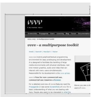
VVVV is a visual programming environment developed in Germany. Sebastian Oschatz and Max Wolf started it in 1998 within the framework of MESO (http://www.meso.net/vvvv). Sebastian Gregor joined a little later, and in 2000 Joreg started to work on the user interface. The first public release was in 2002. Joreg and Sebastian Gregory have been leading the development ever since.
You may have seen other video, animation or 3D software with similar interfaces, like Eyeon Fusion, Blender, 3DS Max, Nuke, UDK, Unity etc. There are other programs that look more like VVVV, including the multiplatform Max/MSP and PureData (PD), Quartz Composer (which is integrated into OS X), EyesWeb and the Windows only TouchDesigner.
Max/MSP (http://cycling74.com/products/max/) and PD (http://puredata.info/) are almost brothers because they are both developed by Miller Puckette. The difference between them is that Max is proprietary software and has a user-friendly interface, while PD is an Open Source application. They are usually used for sound generation and control, but many video devices have been integrated in them over the years (like a node-based Shader editor in Max).
EyesWeb used to be the best software for recognizing and tracking a human shape, so it was mainly used in theatres and dance performances. Its most popular use case was motion detection, with the data transferred to another machine responsible for the visuals, generated in a different environment. Unfortunately this software is often overlooked / has been surpassed by the development of alternatives.
Touch Designer is the closest to VVVV regarding its performance (http://www.derivative.ca/). In contrast with , its user interface is reminiscent of 3D softwares'. It is also more expensive than 0. It costs between 600 and 2200 USD while VVVV is free for private use. Touch Designer's great innovation is the use of Cuda for processing effects which provides for a higher performance than any competitors, since calculations are done on the graphics card rather than on the computer's processor.
VVVV is primarily used for art projects, video-installations, theatre productions, exhibition interfaces, building and object projections (mapping) and projections at concerts. Beyond real time audio and video synthesis, it also serves as a versatile controller for physical objects: motors, relays, LEDs, lights (with Arduino). Moreover, it is useful for controlling theatre and concert lighting, as it is compatible with Artnet and DMX systems. It also has a built-in Timeline, which makes it an ideal tool for music animations, interactive systems, and sound or sensor data reactive installations.
Furthermore, VVVV can be controlled with external devices. These can be internal or external sound (based on volume or frequency changes), tablets, joysticks, Wii controllers, Microsoft Kinect or Primesens 3D cameras, conventional cameras (light or motion detection), MIDI controllers, sensors and many other things. In fact, users are continuously uploading new external software to the forums and to the software's own website, expanding the range of compatible input devices. Additionally, uploads include new effects and simulations (like Bullet Physics which is used in games, physical simulations used in 3D modelling, or the popular GPU Particle Systems). If you are an advanced programmer then you can also write your own nodes and effects in C# or calculate the different transformations on the GPU (similarly to Cuda or Hlsl Shader).
The real advantage of VVVV compared to other 3D software is that it performs the rendering in real time, which makes the development process much faster. Conversely, real time rendering means that the render quality suffers, especially compared to other software which focuses on superior rendering. A lot of features are missing (like shading, blurring and other effects) that we are used to in other programs. However, VVVV is actively developed and constantly improving.
VVVV is currently a Windows only application because it uses the .Net and DirectX9 frameworks for visualization. Interestingly, at the latest developer conference, entitled Node Workshop, an OpenGL-based initiative was presented, which means that VVVV might become multiplatform in the future.
The most important development of recent years, which was started by a user called Vux, is the implementation of DirectX 11 support for VVVV. This is important because the program is based on DirectX 9 at the moment
which is a relatively old visualizing framework. The newest games are all written in DirectX 11, since it can produce more realistic effects, offers better performance and it is more efficient. Unfortunately, the aforementioned VVVV support is still in Alpha state, so we have to wait for it a little longer.
In the attached video you can see the most significant VVVV works of recent years.
Enjoy the movie and have fun learning!
Figure 1.1. max
Figure 1.2. PD
This material is about learning how to use VVVV
Figure 1.3. Eyesweb
Figure 1.4. Touchdesigner
Figure 1.5. VVVV
This material is about learning how to use VVVV
Figure 1.7. Lightmare_screens
Figure 1.8. Lanvideosource
Figure 1.9. Microdee_screens
This material is about learning how to use VVVV
Figure 1.10. u7angel_still
Figure 1.11. Unc_sreenshot13
Figure 1.12. Mr_prudence_Parhelia
Figure 1.13. Elliotwoods_Asse
This material is about learning how to use VVVV
Figure 1.14. Patxi7 Ehime Daruma
This material is about learning how to use VVVV
Figure 1.16. Unc_screenshot 13
Figure 1.17. Lecloneur_screens
Figure 1.18. Sebl
This material is about learning how to use VVVV
Figure 1.20. Lorenz_2
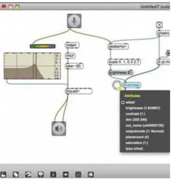
Figure 1.21. Brozzmical_screen
Figure 1.22. Lechloneur_screens
Figure 1.23. Lechloneur_screens
This material is about learning how to use VVVV
Figure 1.24. Vux_screenshot
Figure 1.25. Vux_screenshot
Figure 1.26. WirmachenBunt, Mutabor Design G
This material is about learning how to use VVVV
Figure 1.28. Eletromeier_screens
Figure 1.29. Vux_sreenshot
Figure 1.30. Dottore_screensh
Figure 1.31. mr prudence_Isograms
This material is about learning how to use VVVV
Chapter 2. User interface, language, menu system, the Inspektor and the use of help files
2.1. First steps, installation and useful tips
It is generally recommended to use the most up-to-date version of VVVV because the developers are constantly fixing the known bugs while extending the software. However, in case you find any annoying system errors you should go back to a previous version.
First of all, download the latest release of the software from http://vvvv.org/downloads. It is important to download the addon pack as well because this contains very useful extensions which are used in many patches.
Figure 2.1. Downloading VVVV
It is discouraged to use the built-in compression software of the operating system with the downloaded files, because it can leave some parts of the package unpacked. You should use Winrar, Winzip or 7zip instead. You need to copy the addon pack’s zipped content to the root directory of the VVVV library. When the above is done you need to run the crack.exe file which is in the VVVV library. Without running this, the software will not recognize the *.v4p extension as default. It also shows if any of the necessary software is missing that are needed to run VVVV.
Figure 2.2. crack .exe
User interface, language, menu system, the Inspektor and the use of
help files
There is only one last important step left to do to run the software: setting the Administrator mode. If this is not permitted, the program will still run but it will be useless. This setting exists since Windows Vista and can be activated in two ways:
• Authorizing the whole operation system to be Admin. For this you have to choose the Never notify option under User Accounts within the Control Panel. After restarting the computer, VVVV will run as expected.
Figure 2.3. Administrator mode
• Setting only VVVV as Admin. For this you need to right-click on the VVVV.exe file and under the Compatibility menu within Settings, choose Run this program as administrator. It is important to note that if you use this option you need to do this every time you install a new version of the software.
When everything is set up, launch the VVVV.exe file.
2.2. The interface
User interface, language, menu system, the Inspektor and the use of
help files
Three different kinds of menus can be launched from the user interface:
• The first one is the node list. This can be launched by double-clicking the left mouse button. You can search here with typing or right-clicking. When you start typing, the menu will show only those nodes that start with that particular letter. When you right-click, the nodes will appear grouped by functions. This can be useful when you don't remember the exact name of the node that you are looking for, but you know what it is used for.
Figure 2.6. Two left clicks
Figure 2.7. Two left clicks + a right click
User interface, language, menu system, the Inspektor and the use of
help files
• The main menu can be launched with a middle click or by right-clicking while holding down the Space button. In this menu you can find some familiar functions followed by their shortcuts.
Figure 2.9. Main menu
Finally let's discuss some basic concepts. A program written in VVVV is called a patch and the little boxes that we connect within the program are the nodes. The patches are saved with a *.v4p extension.
These are essentially text files that are slightly similar to *.xml documents. They contain the positions, parameters and the connections of the nodes. Every node has inlets and outlets that are indicated by small grey boxes. Imagine it as if the functions of a conventional text-based programming language were boxed in and its variables and outgoing parameters were the inlets and outlets. The only difference is that here you do not need to declare function; you only have to refer to them.
Now double-click with the left mouse button, choose the lfo function and press enter. You can see five inlets on the top of the box. If you hover your mouse over them, the program shows the names and the variables of the inlets: Period: 1.00s, Pause: 0, Reverse: 0, Reset: 0, Phase: 0.00. The outlets are on the bottom of the box:
Output: 0.xxxx~, Change: 0 (this will change to 1 every second), and you will see a number at the Cycles outlet.
User interface, language, menu system, the Inspektor and the use of
help files
If you want to know more about a node, how it works and what it can be used for, then click on it and press the F1 function button. This opens the node's help file. (In the case of the lfo node it’s called LFO (Animation) help.) Fortunately, VVVV help files are very readable and informative.
If you want to use a patch that you found in a help file, but you don't want to re-create it, then you can copy it after selecting it, pressing Ctrl +c, and pasting it to your own patch with Ctrl + v.
Figure 2.11. Lfo help file
If you want to navigate inside a patch, you can use the mouse scroll or press and hold the right mouse button on an empty grey surface while moving the mouse. The whole patch will move inside its window.
2. Video Lesson
Chapter 3. Message types, inlets and outlets
In VVVV a message box is called an IOBox. There are several different kinds of message boxes, depending on their application. We distinguish number (Value), text (String), colour (Color), data (Node) and drop-down menu (Enumeration) boxes. Each IOBox parameter, i.e., the number of messages that they contain, the font they use, and much more, can be precisely adjusted in the Inspektor - as it is explained later in detail.
Figure 3.1. The Message menu
Let's discuss the most common types of messages, the numerical ones, first! In VVVV you can choose from a number of predefined variations if you double-right-click any free surface on the grey background. This will bring up the message menu, where you'll find a list containing Bang, Toggle, Integer, 2D Vector, 3D Vector and 4D Vector named functions which are all number-based messages.
A Bang megnyomáskor egy pillanatra felvillan, és kiküld egy 1-es üzenetet, majd visszatér 0-ra. Ezt például léptetéshez, törléshez és hasonlókhoz lehet használni.
The Bang and Toggle have similar functions. Both of them are a kind of switch which sends 0 by default. The Bang glows for a moment when pressed and sends the message 1 and then goes back to 0: this can be used for example to scroll, delete etc.
When the Toggle is pressed, the output switches to 1 from 0 and remains there, while pressing it again resets it to 0.
It is easy to tell them apart by looking at their edges. The Bang has rounded edges while the edges of the Toggle are square. It is worth bearing in mind that the messages in VVVV primarily act to right click and not to the left one, as usual. (Double left click changes the message box to keyboard input mode.)
Now, try the buttons! Double-right-click on the grey background and create a Toggle and a Bang. Under both of them (also with right click) create two simple number boxes. In order to see the change, the switches must be connected to the numbers. This can be done by connecting the outlets (the small grey squares found on the bottom of the objects) of the Bang and the Toggle to the inlets (on the top) of the number boxes. If you start
Figure 3.2. Bang and Toggle
The traditional number boxes which are easy to make with a double right click also have some predefined standard versions: these can be found in the message menu among the vector ending ones. These are mainly needed if an inlet needs more than one value; for example in the case of x-y-z coordinates. This can also be set manually in the Inspektor while even more numbers can be added.
Figure 3.3. Vector types
The text box is primarily used for text input, because some nodes can only receive text-based messages.
However, you can also write numbers, but you will not be able to connect them to any number-based inlet. The
Message types, inlets and outlets
The best way to try what we learned so far is for you to choose the text function with a double left click. The program offers all the nodes containing text. You need the very top one, Text (ex9). Hovering your mouse over the inlets of the box, you will see that there are many parameters to change, similarly to the ones found in the interface of text editors.
Figure 3.5. Text module
One of them is called Layer: [Supports: ex9 layer]. This means that the inlet is expecting an ex9 renderer, so to visualise the text module a render window is needed. To open one, you have to write renderer to the node menu and choose the top one called Renderer (ex9). Just click on the outlet of the text that will blink, indicating that it can be connected to the inlet of the Renderer. When you connect them, the text “vvvv” will appear in the system window. This is the default value of the Text object.
Figure 3.6. Hello Renderer
In order to edit it, click on the outlet of the String box and you will see which inlet of the Text you can connect it to, because the right one thickens. Right-click on the String and write something, for example “HELLO”. You could see earlier that amongst the inlets of the Text box there is one called size. If you right-click on this inlet and start dragging your mouse, you see the resolution of the text changing, and not its size. Write “300” after a simple right click and press enter.
Figure 3.7. Resolutions 10 and 300
In order to change the size of the text, you need to connect a transform box as well. Click on the node menu, type transform and choose the Transform 2d function. You can connect the outlet of the transform to the second inlet of the Text. If you hover over the inlets of the transform, you can see parameters like x-y position, scale, rotate etc. You will need the Scale x, Scale y functions. Make a number box and connect its outlet to both of the scales. The text disappears from the Renderer because the size of the scale is set to 0. Change it to 0.5 for instance.
Figure 3.8. Scale X Y
Message types, inlets and outlets
Translate x, y is responsible for the position of the text inside the transform node. To set the position of the text, connect the first two outlets of the Renderer (x and y) to the Translate x, y parameters.
Figure 3.9. Moving text with mouse
You can control the colours with the Color message type. Make two Color boxes, connect one of them to the Renderer and change its colour by right-clicking while dragging the mouse. Connect the other Color to the color inlet of the Text box to change the colour of the text.
Figure 3.10. Hello in colour
In order to control it with mouse position you need a box that transforms the numbers to colour. There are many kinds of nodes that do this, but use HSL (Color Join) for now. As the name implies, colours can be mixed with Hue, Saturation and Lightness parameters. If you connect its outlet to the inlet of the Color box which is connected the Text box, the text will change to white because the Lightness is set to 1 by default. So despite adjusting the Hue, the text will remain white. However, if you change the Lightness to 0.5, then you can get full colours. Next, you can make the colour depend on the position. All you need to do is to connect the x outlet of the Renderer box to the Hue inlet of the HSL (Color Join) box.
Figure 3.11. Adjusting HSL with mouse position
1. Video Lesson
Chapter 4. Komplexebb matematikai feladatok, fájlba írás és olvasás
First let’s look at the most often used basic operations: addition, subtraction, multiplication and division. Create one of each, as the picture shows below! The software recommends many types of basic operations in the node menu, but for now we only need the ones ending with value. Their usage is pretty straightforward. The Spectral Value node adds or multiplies vectors comprised of multiple numbers.
Figure 4.1. Basic mathematical operations
There are two ways to solve a formula. You can either put it together yourself using the operations it contains, or you can use the Expr module to define whole formulas.
Figure 4.2. Complex mathematical operations
Since it is often necessary to let several things interact for starting an operation or triggering and inlet, familiarity with logic gates is a must for the VVVV user. Logic gates are as follows: the outlet of the OR module change to 1 immediately if it receives a 1 on any of its inlets - pretty useful when an inlet (of a module reset for example) gets impulses from many places to implement an action. The outlet of AND only changes to 1 when all its inlets hold 1. The XOR is the exact opposite, as it only sends 1 if its inlets are all different. The NOT module inverts its inlet, meaning if it receives 1 it will output 0.
Figure 4.3. Using logic gates
Komplexebb matematikai feladatok, fájlba írás és olvasás
If the result is not in the proper range, it can be adjusted with further multiplication, division or adding. The Map module makes this a whole lot easier. The range of the incoming data can be adjusted on the 2nd and the 3rd inlet of Map while the range of the outgoing data is adjusted on the 4th and 5th inlet.
Figure 4.4. Resize
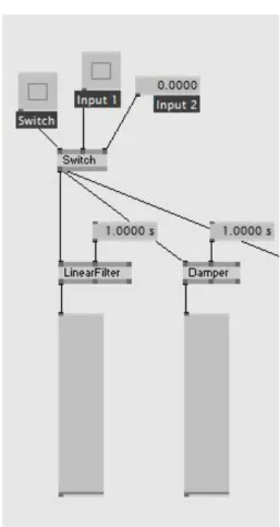
In order to change between two values or to choose between two inlets of origin a Switch is needed. It is really easy to multiply the inlets and outlets of the gates with the help of the Inspektor. This can be seen in Figure 4.6.
Figure 4.5. Inlet and outlet switches
Figure 4.6. Switches with multiple inlets and outlets
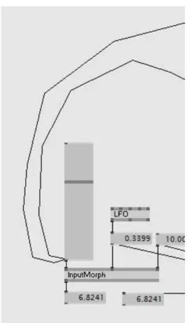
The easiest way to fade between two inlets is with InputMorph. This can be achieved with ordinary modules as well, as you can see in Figure 4.7.
Figure 4.7. The InputMorph
Komplexebb matematikai feladatok, fájlba írás és olvasás
If your inlet changes but the transition between states is not good enough, you can smoothen it with filters like LinearFilter, Damper, DeNiro, Oscillator or Decay. LinearFilter creates a linear transition between two states with a given time. Damper does the same with a quick attack and a slow decay (similarly to a release of a spring) while the DeNiro has a slow attack and a short decay (just like a car). The Oscillator works similarly, but it has a release time, too. Decay is a kind of LinearFilter as well, but its attack and decay can be adjusted via its 2nd and 3rd outlet. Many more parameters can be adjusted with the ADSR envelope generator, which may be familiar from synthesisers.
Figure 4.8. Filters
Figure 4.9. Decay and ADSR
Komplexebb matematikai feladatok, fájlba írás és olvasás
If your inlet consists of multiple values and you would like to smoothen it, then you need to use the B-Spline module. It is expecting a LinearSpread on its first inlet. With this you can set how many numbers you want going out. This means that if your source is made of, for instance, 12 numbers, and LinearSpread smoothens it using 100 numbers, then it will mediate 100 values. The module’s second inlet is expecting the control inlet while the third one is used for setting the level of smoothness. If the latter is set to 0, then the outcome will be square, if it is set to 1 it stays the same, while if it is set to 3, the result will be soft.
Figure 4.10. B-Spline
We mentioned vectors before, but it is time to look at them in detail! Every message type can consist of multiple messages and a number of methods for their composition and interpretation. The main modules which have been available for a long time, are the Vector (joint), Vector (split), Cons, and Stallone. There are four different kinds of Vectors: 2d, 3d, 4d, and Spread. The first three have a fixed number of inlets and outlets while the Spread’s inlets and outlets are adjustable. The Vector module works in a way that if you have multiple values on your inlets, then the first one of each will make the first row, the second of each the second row, and so on. To display the values that are received in the first inlet in the first row, followed by the numbers of the second inlet, et cetera, you can use the Cons. Stallone module – a more modular module, since you can set the number of its inlets and outlets, and even the listing method in the Inspektor.
The Zip and Unzip modules appeared only recently. They are much more effective when you work with more than 25 numbers at a time, so you should use these when listing many numbers. The number of inputs and outputs of these modules can be specified using the Inspektor.
Figure 4.11. Vector types
Komplexebb matematikai feladatok, fájlba írás és olvasás
Figure 4.12. Vector, Zip, Cons and Stallone
To make a list of numbers from, for example, zero to one hundred, use the I module. It works similarly to LinearSpread: if you write 0 to its first inlet and 1 to its second (Width), then you will get a linear list between - 0.5 and 0.5. You can achieve the same result but with random values if you use the RandomSpread. You can set the level of randomness with its RandomSeed inlet. The CircularSpread creates numbers along a circle that have x and y values. The x and y parameters, setting the position of the centre of the circle, and other parameters for the width and height, as well as for the filling, can be adjusted.
Figure 4.13. I
Figure 4.14. LinearSpread and RandomSpread
Komplexebb matematikai feladatok, fájlba írás és olvasás
Figure 4.15. CircularSpread
We will discuss reading and writing files in the last lesson.
1. Video Lesson
Chapter 5. Rendering types
Let’s look at the first render module that is in the node menu which is also the most often used, the Renderer EX9! All two- and three-dimensional modules can be displayed with this.
In order to try the module you need to make a quad DX9 first, and connect it to the render module. A white square will appear in the render module that needs to be resized for full screen. You can do that by changing scale x and scale y to 2 on the transform inlet. Quad is a simple slab that is capable of displaying pictures and videos. You can load images with the Filetexture module. If you connect the outlet of the module to the corresponding inlet, the clean slab will change to black (its default state) until the desired picture is selected on the first inlet of the Filetexture module.
If you know in advance that you will always need a full screen display that you will not necessarily want to resize, then the best choice is the FullscreenQuad module, since it renders full screen by default. Anyway, if you want to resize it later, it is possible with the transform inlet, just like in the case of the Quad.
Figure 5.1. Full Screen Quad Render
Both modules have color inlets as well, for setting the colour and transparency of the image. The Texture Transform inlet is also worth noting which is used for resizing textures. This can be interesting when your texture is smaller than the displayed image. In this case the software will offer functions that allow you to repeat the texture, stretch the last row of pixels etc. In the case of the Quad, these functions are available through connecting the Address to the Sampler State function. In the case of the FullscreenQuad module the tab before the last, called Texture Address Mode is there to do the same.
These are the basic functions of the render modules. We will talk about them in more detail in the following lessons.
Figure 5.2. Quad Render
The next module in line is the SVG, i.e. Scalable Vector Graphics which is an xml-based vector display. It was made for the web, and also contains a Quad, where transforming and colouring operates in a similar manner as the EX9 type of Quad, but this one renders pixel-based pictures a little harder. If you search for modules related to SVG you would see that there are hardly any available. This program is mainly used for generating simple two-dimensional graphics and it has a great disadvantage: high CPU usage. You should not dig any deeper unless you need to save your patch as XML.
Figure 5.3. SVG Render
Rendering types
Another one is the TTY render that is used for displaying messages. It is mainly used for displaying error messages, but it can also be programmed with a TTY type Write module.
Figure 5.4. TTY Render
The GDI i.e. Graphic Device Interface render is also a two-dimensional renderer for line-based graphics. The related modules are: Point, Text, RoundRect, Circle, Line and the BézierLine. Unlike the others, this has no transform inlet, but all its parameters can be set inside the module, such as the x and y position, width, height, colour etc. In some rare modules, the line thickness can be adjusted as well.
Figure 5.5. GDI Render
Finally let’s talk about the SWF renderers that are used for displaying Flash images. There are two options for displaying these file types.
The first one is the Flash renderer that is suitable for displaying Flash files without external modules. You can load the file in this render module, set the screen size, loop points, as well as the start and end key frames.
Figure 5.6. Flash Render
The other option is the Flash EX9 for which you must use an EX9 render module. It works like a Quad but it plays SWF files. For external control, apart from the variables mentioned above, you can use mouse position or mouse press which can be very useful.
Figure 5.7. Flash EX9 Render
The next module is the HTML string. You can use it to render HTML codes. It also lets you embed videos.
Figure 5.8. HTML Render String
Rendering types
Figure 5.9. HTML Render
Chrome integration is forthcoming in the next versions.
1. Video Lesson
Chapter 6. Layers
Start by creating two Ex9 Quads and a render window. Connect a 2d Transform to each Quad.
As you have already experienced when we discussed numbers, only one parameter can be connected to one inlet, unless you have joined them using a vector. Images work in a similar way. If you want to display two or more Quads in the same render window, you will need to use a Group. You can adjust the number of inlets in the Inspektor.
Create a Group and connect two Quads to it. Only one square will appear because the two Quads are on the top of each other. In order to place them next to each other, write 0.5 in the X position of one of the Transforms and 0.5 in the other one.
There are two types of texture loading modules: one of them is the FileTexture which is used for loading still images. This should be familiar from the previous lecture. The other one is called FileStream (DShow9) and used for loading videos, sound and midi.
Figure 6.1. The FileTexture
FileStream has the following inputs: play, loop, start and end point, jump, cue, speed and file name. The following outputs are useful: audio out, midi out, video out, length and current position. In order to be able to connect the video output to a Quad, it has to be transformed with a VideoTexture module, because this outlet is a DirectShow type originally and you will need a TextureOut.
On loading and starting a video you might not see anything happening: this may be due to the fact that the end time is not set at its input. You can achieve this by connecting the Duration outlet to the EndTime. This will not take effect immediately because of the resulting feedback loop, which is not supported by the system. The signal has to be delayed by 1 frame using the FrameDelay module. You will use this module often because it has texture and text types as well. When this is done, you can connect the inlet and the outlet and the video begins to play.
Layers
The Filestream can handle quite a few formats, but it can take time until you find the right one. If you know that you don’t need audio and you don’t want to change the start and end points of the video either, then you should use the MediaPlayer module. It has built-in FrameDelay and VideoTexture, too.
There is already some rudimentary integration of the VideoLAN project’s multimedia player, the VLC Player.
This will bring significant changes because VLC can play almost any kind of file type and a lot of player functions can be reached from it. However, in this lesson, we do not dwell on it because this module is still in a beta stage and does not work perfectly.
http://vvvv.org/contribution/vlc-plugin-%28beta%29-a-new-audiovideo-player-to-texture-plugin
You can also use only one Quad for many layers. In this case you need to control it using more parameters and Group is not necessary.
Figure 6.3. Textured layers
The following example shows how you can choose a number of images from Quad’s texture with an HSL module.
To make a transition between the layers, make a Quad and connect it to a render window. After that, connect an HSL Color Join module to the color inlet of the Quad. The next step is to connect a LinearSpread to the HSL module’s Hue and Alpha inlets and set them 0.5! Thus the value will be between 0 and 1. Change the Spread Count to 10 on the last outlet, so you have 10 values. Do the same on the other LinearSpread!
Figure 6.4. HSL and LinearSpread
Now you see a white square in the render window. This means that the Lightness is on 1: change it to 0.5! You get a reddish colour which can be changed by connecting a LinearSpread module to the Alpha inlet and change its Phase inlet. Alternatively, connect an LFO slowed down to 3 seconds.
With some texture, we will be able to see our work more clearly.
To generate the texture, create a Text Ex9 Texture woei module and connect it to the texture input of the Quad!
The text “VVVV” appears on the render. In order to get 10 different texture layers from this Text module we will need an i module and a SpellValue. The i module makes integers between two given values, while the SpellValue generates letters from these numbers. Connect the two and write 65 and 75 to the first to inlets of i.
Choose the ASCII function in SpellValue’s drop-down menu.
Figure 6.5. Text texture
You may now see the letters from A to Z, because in the ASCII character table the ABC starts at number 65. If you connect this to the correct inlet of Text, then every letter will have different colour. Resizing is needed in
Layers
The only difference between the following example and the previous one is that it is shifted in space and not with HSL. However we are working with a FileTexture and a FileStream compared to a single source of texture.
Similarly to numbers, you will need a Cons module in order to add them. As we only have two textures, the Quad has to repeat it five times to get the required ten textures.
Figure 6.7. Transform with LinearSpread
The render doesn't normally have a perspective: a Camera Softimage module is needed for this. When working with several layers, it is really important to set the Windowed Deptbuffer Format of the renderer in the Inspektor to D24X8, because otherwise it does not render the screen correctly.
Figure 6.8. Layers in Perspective
Our last example is going to be a little more difficult than the previous ones: in this one we are going to re-size objects with mouse-distance and distort them on button press.
As a first step we need to make a 25x25 Quad net with the help of the Cross module (without this the squares can only be put diagonally).
The Cross does nothing else but gets the positions of module's first inlet and repeats it with the values of the second inlet, i.e. if on the first inlet the value is 5 and on the second one is 3, then we will get a 5x3 matrix.
After creating the Quad-net, you can determine which square is the closest to the mouse with the Points2Vector.
Connect the x and y values of the Cross module to the first two inlets of the Quad module and connect the x and y values of the Mouse module to the third and the fourth one! By doing so, you get a list on the third outlet, called Length. This is the distance we are looking for! If you connect this to a Map and write 0.1900 to the Destination Minimum and 0.12000 to the Maximum, and finally, connect the outlet to the x and y values of your transform module, it will start following your mouse.
Figure 6.9. Cross2d and a 20x20 Quad
The next one is a very spectacular distortion: the Attractor 2d. Similarly to Points2Vector it also expects the position of the squares on its first and second inlet and the position of the mouse on the third and fourth.
The remaining inlets are the Strength, Power and Radius. With the latter you can set the level of distortion (set this to 1.4200) while the first two is responsible for its strength. Create an Or and wire it to the left and right mouse click. Connect a Map to the right click and type -2 to its minimum outlet and 2 to its maximum! Multiply its outlet with the outlet of Or and connect it to the Strength. Write 1.290 to the Power.
Figure 6.10. The Points2Vector controlled Quads
Layers
The effect is ready which you can adjust later when you get more familiar with Attractor 2d's behaviour.
Figure 6.11. The Final Render
1. Video Lesson
Chapter 7. Rendering 3D Objects
In this lesson we are going to have a look at three-dimensional renderers and their editing possibilities. Let’s start with the most often used 3D file loaders and the most important renderers!
You may know Scene, the Assimp file loader from other 3D software. This is an open source 3D object loader which can handle many kinds of 3D formats like .dae, .blend, .3Ds, .ase, .obj, .stl and so on. Hopefully, common 3D modelling features like bones and animation will be integrated shortly.
After loading a file, you will definitely need a Mesh Assimp module that converts the output of Scene to Mesh.
There are many other modules for Scene like the Camera which reads the camera position saved in the object, Material which is responsible for colouring and texture data, and the Node which gives the transformation data of the object.
It is important to know that the Scene loader permanently optimizes the vertexes. This can cause problems when you save many shapes with the same vertex and would like to morph between them. This does not work as expected because the vertex numbers are not the same after loading.
Figure 7.1. A Scene file loader
The other file loader is the ColladaFile. It can only read .dae files but it has many functions. A lot of things that are missing from the previous loader are already integrated into this one: we can use bones, or movement that was saved with external software, as you can see in the example file. The skeleton can be controlled with a
Rendering 3D Objects
Figure 7.2. A Collada file loader
The third and simplest 3D loader is the XFile which uses .x files (the DirectX 3D format). This format has neither an extra module, nor a Transform outlet. However, it is really easy to edit and create new files using a custom program called Writer.
Figure 7.3. Xfile module
Figure 7.4. 3d Render
Create a DrawFixed module, a renderer and a Camera Softimage and connect them! Change the Initial Distance of the Camera module to 1. (Don’t forget to set the DeptBuffer to D24X8, otherwise you will get an interesting sight.) In order to make a Mesh net choose the Grid EX9.Geometry module and connect it with your DrawFix.
The Grid has two Resolution inlets (X and Y). Change them both to 20, for instance! When you create a Fill module and connect it to your DrawFix and select the WireFrame function on its right inlet, its resolution becomes visible.
Figure 7.5. DepthBuffer setup
Rendering 3D Objects
Every Mesh can be divided into 3D positions. Create a Mesh Geometry Split module alongside the VertexBuffer Geometry Split module and connect all three! The Mesh module has two outlets: VertexBuffer and Indices.
VertexBuffer normally has a Position XYZ and a Normal XYZ. You have to set the Texture Coordinate 0 to 2d, because texture coordinates will be needed for the upcoming exercises.
Create the Mesh Joint and the VertexBuffer Joint after that, which are the opposite of the previous example. You will mostly need the Position XYZ, because this is what has to be modified later on, so the rest (Normal XYZ and texture coordinates) can be connected between the VertexBuffers just like the indexes of the Meshes. You can split and merge the positions using the Vector 3d Split and the Joint. You can connect the X and Y values so the Mesh Joint can already be connected to DrawFixed.
Our aim now is to modify the Z positions. We could do this with Random spread but instead we are going to use an image for this. For this purpose we are going to get the necessary colour information with the Pipet Texture Simple module. This tool has three inlets: a texture where the source image must be loaded, and X and Y coordinates. Use the Plasma module for texture. This generates some plasma on which saturation, size and density can be set manually (while at it, bring the saturation down to 0). Connect this with Pipet and also connect the X and Y values of the Vector Spilt module to the other two inlets. This will query the colour specified by the X and Y coordinates of the Grid module from the texture.
Figure 7.7. Grid transformed with Pipet
When this is all done, you will get 400 colours on the outlet of Pipet, i.e. 20x20 values. If you connect this to a Color Split you will get the luminosity. You can get the Z coordinates with this. (It is recommended to resize the given data with Map, because there will be a huge difference between 0 and 1, so type in 0.2500 on the outgoing minimum and 0 to the outgoing maximum. The outgoing stream has to be inverted because otherwise the darker values will rise and the lighter ones will descend, which is the opposite of how waves look.)
The easiest way to make the plasma move is by adding the first and last outlet of an LFO while changing its timing to 10 seconds. Connecting this to a 2d Vector and then into the Offset inlet of the Plasma module will start the motion instantly.
1. Video Lesson
Chapter 8. Transformation and grouping
In this part we are going to get familiar with different transformations, grouping and basic physics.
You should have noticed that you can connect all the transforms to each other. You can define the position of an object with the first layer of transform and modify the whole patch with a second layer. This could be a solution in many situations but there are scenarios when we need to multiply our objects or modify only a part of them, in which cases this approach may not work.
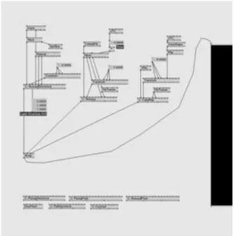
Figure 8.1. Normal Transform
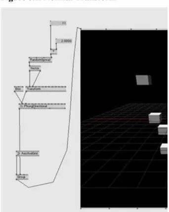
Make a Render with a Group and connect an AxisAndGrid to the first inlet of the Group and a PhongDirection to the second one. Connect a Box EX9Geometry to its inlet and a 3d Transform to the transform inlet. Create a Camera (Transform Softimage) and connect it to the View and Projection inlet of the Render. Make 10 random X and Y positions with RandomSpread so your boxes are visible in the 3D space. Zoom in or change the width of Random if needed, so the objects are clearly distinguishable. If you connect a Transform 3d and start rotating your elements, you will see that it moves all of them. Instead of Transform you can use Rotate, Scale, UniformScale, Translate modules, too. With these you will only be able to use the single transformation that you need.
Figure 8.2. Parental Transform
You can move the original Transform all at once in another way, too. For this, you need to connect a „*
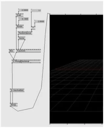
(Transform)” between the Phong and the original Transform and multiply its second inlet with another Transform. You can also rotate the individual objects one by one with multiplication. You can get all the transformations from the original Transform with a Decompose Vector node. If you want to rotate your objects around their own axis, then you simply need to connect the X Y Z coordinates to the X Y Z inlets of the transform and to Center X Y Z. This way all the objects will get their own origin. Once this is done, you can control the rotations with SetSlice or RandomSpread.
Figure 8.3. Transform Multiplication
Transformation and grouping
Figure 8.4. Decompose vector
With the GetSlice node, we can select different items of a list containing multiple Transforms. It has three inlets.
The first one is the Transform; the second one is the Bin Size, with which we can set the number of selections, and finally the Index which corresponds to the designated items. If we connect this to a Decompose module we get the precise data of the chosen transforms.
Figure 8.5. GetSlice Transform
We can give brand-new positions to our objects one by one if we connect a SetSlice (Transform) between the original Transform and Phong, because this module has two Transform inlets. The first one is the original and the second one is the new position. There is also a Bin Size and an Index inlet with which we can set to which elements the transformations are applied.
Figure 8.6. SetSlice Transform
Figure 8.7. Apply Transform
Transformation and grouping
Another way to position elements is with ApplyTransform. To move our objects, the X Y Z coordinates have to be connected directly to the object and to the first inlet of a Transform. We can connect the X Y and Z outlets to a normal Transform 3d. In this case the module calculates the rotation and moves the object in space, but does not rotate it at the same (as before). We can use this module for repositioning or rotating Vertex positions, for example.
Figure 8.8. Spread Transform Multiplication
Sometimes you need to multiply a Transform containing many elements (this does not work with another layer of transform). You need to make a Node message for this. You have to connect Transform, used for multiplication, to its left inlet and the SpreadCount of the original to its right inlet which is the Bin Size. Finally we have to connect it to the previously used multiplication. As a result, it will multiply the objects.
Let's talk a little physics now!
There are three different kinds of physics available in VVVV:
Box2d http://en.wikipedia.org/wiki/Box2D,
ODE http://ode-wiki.org/wiki/index.php?title=Main_Page
Bullet http://en.wikipedia.org/wiki/Bullet_(software)
You have probably met with the engine of Box2d in various computer or mobile games (it is usually used in motorcycle and tank games). It has been integrated to VVVV, too. There is an external object called box2d playground made by TGD with superb user interface design. You can find it on the Contribution page here:
http://vvvv.org/contribution/box2d-playground
Először vegyük a Box2d-t, ezzel az Engine-vel már találkoztál különféle PC-s, illetve telefonos játékokban (többnyire motoros és tankos játékokban használták). A VVVV- ben is integrálva lett, és ebből egy nagyon jól használható kezelőfelülettel külön letölthető kiegészítőt készített TGD, mégpedig a box2d playground-ot. Ezt megtalálhatod a Contribution oldalán: http://vvvv.org/contribution/box2d-playground.
Figure 8.9. BOX2D Interface
When starting the patch you can see that the user interface appears in a DirectX render. You can make static and dynamic objects like squares and triangles with it. Pre-set elements are also available, like a grid or boxes lined up like text. Their settings can be modified in the CreateBoxTypo or the CreateBoxArray modules within the CreateObjects library. It is also possible to load and save sets of elements. If you click on the Load button, a default “skeleton” loads. On this example you can see the joining points of the specific elements. The fastest way to create this is by dragging elements on top of each other in Halt World mode and right-clicking the point where you want to put the joining points.
Figure 8.10. BOX2D file load
Transformation and grouping
The Bullet physics comes with the addonpack, and after copying it, you can find examples in the .\addonpack\girlpower\BulletPhysics\ library. Bullet is a really complex 3d physics engine that is used by many well-known companies in physical simulations. If you open the example patches, you see that they work a little differently than usual. They are not connected, not even with a Send and Receive module. You can make static or dynamic objects with CreateRigidBody and CreateSoftBody in the 3D space. Furthermore, these objects can make simple geometric forms (it has a built-in Bullet module) or you can load your own objects, because the aBVH module can convert the Mesh file to the correct format.
Figure 8.11. Bullet in OpenCL
Figure 8.12. Bullet BVH Mesh
When creating physics with SoftWorld, you get the information required to control the modules in the final Render. You get the mesh forms from the SoftWorld with RigidBody. The transformations that you can connect to a PhongDirection are available from the GetRigidBodyDetails.
Figure 8.13. Soft rigid
Transformation and grouping
Chapter 9. Effects and Plug-ins
In this tutorial we are going to get familiar with the different integrated modules. If you have already installed the Add-on Pack, your version of VVVV already has plenty of new plug-ins and effects beyond the basic functions.
Figure 9.1. Effect list
Typing “FX” pulls up a list of the available effects. Most of them have been developed the UNC Company.
Many effects, like holes, blurs, distortions, colour corrections should be familiar from popular image and video editing suits.
As a first step, we are going to make a drawing patch made from external plug-ins. You will be able to use this for masking and drawing in other patches. The patch itself is built from the Brush node and the Blend node which are responsible for the addition of images and the Buffer node which is a tool for temporary storage.
Make a Render first and connect a Group to it. Connect a FullScreenQuad to the first inlet of the Group, and Cursor to the second one. Create a MouseState Joint and connect it to the Cursor. Connect the MouseState X and Y and the left mouse button to the identical outlet of the Render, so that the Cursor will follow your mouse movement. You don’t see that happening yet, because there is nothing connected to the texture inlet of the FullScreenQuad, so the whole screen is white.
Figure 9.2. Brush plug-in
Effects and Plug-ins
To resolve this, connect a newly made Brush. If you have a look at its inlets you can see that it has an X and Y position, for brush size and brush intensity. Connect the X Y positions of the Render module to the correct inlets of the Brush and set its size to 0.1500. Create a Blend EX9.Texture Mixer and connect the Brush to its first inlet.
The image to be added the second inlet must be connected to itself through a FrameDelay EX9.Texture. If you connect it to the FullscreenQuad, you will see nothing, so set the Blend Mode to Screen and the Opacity to 0 and then back to 1. Now you can draw continuously.
It might be strange what you see now, because this module draws a little cloud adding a narrow black outline to the brush. This can be corrected in the Brush module by setting the alpha of the Background Color to 0.
Figure 9.3. Blend and Buffer
Connect a Buffer EX9.Texture module between the Blend and the FrameDelay. Connect the left mouse button outlet of the Render through an Or to the Set inlet of the Buffer. In this way, if you connect the right mouse button to the Opacity inlet of the Blend through a NOT gate, the program clears your picture on a right mouse click and draws and stores it on pressing the left mouse button.
It is important to get a totally black picture after clearing the canvas, which implies that you have to make the Brush disappear for a moment. To do this, connect the left mouse button to its Show Brush inlet. Thus the program will only show the brush when the left mouse button is held down. To invert the colour of the mouse pointer as compared to the canvas, make a PipetSimple and connect the Blend outlet to the Pipet.
Figure 9.4. Cursor and Pipet
Effects and Plug-ins
Figure 9.5. Brush patch
This module is expecting the mouse position on its other two inlets – but not between 1 and +1 but from -0.5 to +0.5, so the X and Y outlet of the Render module must be divided by two and connected to Pipet.
Now we are going to learn how to use additional effects in a Render patch.
Figure 9.6. DX9 Texture
Every Render module has a texture outlet which you can connect to a newer Quad or maybe to a Render.
Normally the effects are all built the same way. If you right-click on an effect node, you can see that it is built similarly to the patches we saw before. The difference is that they use Shaders instead of Quads or other visualizers and the outlet is for a DX9 Texture node.
Figure 9.7. Hidden Render without resolution setting
When using DX9 it is important to set the Render resolution because if not, the program will use the actual window size for rendering. If you set it, then the window size will not matter anymore (even if you make it disappear with ALT+3) – the program will render in the size that you have set. This parameter can also be specified separately in the Inspektor.
Figure 9.8. Hidden Render with resolution setting
Effects and Plug-ins
Figure 9.9. Resolution setup in DX9Texture
Figure 9.10. Alpha texture out
Figure 9.11. Sample effect
Thanks to the developers and users of VVVV there are many plug-ins and accessories available on the http://vvvv.org/contributions website. You can find many plug-ins, projects, device managers and various Shaders in alpha or beta state.
It is worth visiting the site frequently because a lot of people upload useful external patches addressing a wide range of problems. These are usually well documented, right there on the site or separately in the help patch, but if you find a bug or run into a problem, it is good to know that there may be more information on the site related to the patch. The forums are also very useful for finding solutions to specific problems.