Cite as: Rev. Sci. Instrum. 91, 063303 (2020); https://doi.org/10.1063/5.0008512 Submitted: 23 March 2020 . Accepted: 24 May 2020 . Published Online: 09 June 2020
Thomas F. Rösch , Zoltán Szabó, Daniel Haffa, Jianhui Bin , Szilvia Brunner, Franz S. Englbrecht , Anna A. Friedl , Ying Gao, Jens Hartmann, Peter Hilz , Christian Kreuzer, Florian H. Lindner , Tobias M. Ostermayr , Róbert Polanek, Martin Speicher, Emília R. Szabó, Derya Taray, Tünde Tőkés, Matthias Würl , Katia Parodi , Katalin Hideghéty , and Jörg Schreiber
A feasibility study of zebrafish embryo irradiation with laser-accelerated protons
Cite as: Rev. Sci. Instrum.91, 063303 (2020);doi: 10.1063/5.0008512 Submitted: 23 March 2020•Accepted: 24 May 2020•
Published Online: 9 June 2020
Thomas F. Rösch,1,a) Zoltán Szabó,2,b) Daniel Haffa,1 Jianhui Bin,3 Szilvia Brunner,2 Franz S. Englbrecht,1 Anna A. Friedl,4 Ying Gao,1 Jens Hartmann,1 Peter Hilz,1 Christian Kreuzer,1 Florian H. Lindner,1
Tobias M. Ostermayr,3 Róbert Polanek,2 Martin Speicher,1 Emília R. Szabó,2 Derya Taray,1 Tünde T ˝okés,2 Matthias Würl,1 Katia Parodi,1 Katalin Hideghéty,2,5 and Jörg Schreiber1
AFFILIATIONS
1Department of Medical Physics, Faculty of Physics, Ludwig-Maximilians-Universität München, 85748 Garching bei München, Germany
2ELI-ALPS, ELI-HU Non-Profit Ltd., Wolfgang Sandner utca 3., Szeged H-6728, Hungary
3Accelerator Technology and Applied Physics Division, Lawrence Berkeley National Laboratory, Berkeley, California 94720, USA
4Department of Radiation Oncology, University Hospital, LMU München, 80337 München, Germany
5Oncotherapy Department, University Szeged, Szeged 6728, Hungary
a)Author to whom correspondence should be addressed:t.roesch@physik.lmu.de
b)barothszabo@gmail.com
ABSTRACT
The development from single shot basic laser plasma interaction research toward experiments in which repetition rated laser-driven ion sources can be applied requires technological improvements. For example, in the case of radio-biological experiments, irradiation dura- tion and reproducible controlled conditions are important for performing studies with a large number of samples. We present important technological advancements of recent years at the ATLAS 300 laser in Garching near Munich since our last radiation biology experiment.
Improvements range from target positioning over proton transport and diagnostics to specimen handling. Exemplarily, we show the current capabilities by performing an application oriented experiment employing the zebrafish embryo model as a living vertebrate organism for laser-driven proton irradiation. The size, intensity, and energy of the laser-driven proton bunches resulted in evaluable partial body changes in the small (<1 mm) embryos, confirming the feasibility of the experimental system. The outcomes of this first study show both the appro- priateness of the current capabilities and the required improvements of our laser-driven proton source forin vivobiological experiments, in particular the need for accurate, spatially resolved single bunch dosimetry and image guidance.
Published under license by AIP Publishing.https://doi.org/10.1063/5.0008512., s
INTRODUCTION
Laser-driven proton acceleration is a method of growing inter- est. Using a laser as the driver allows for extremely high (TV/m) acceleration fields overμm acceleration distance and, hence, cre- ates a very compact source for protons in the MeV range. Using a petawatt class laser system, protons have recently been acceler- ated up to above 90 MeV.1Furthermore, laser-accelerated protons exhibit a bunch duration on the order of ps and are shorter than any conventionally accelerated bunch. Nevertheless, high particle numbers per bunch are achieved.
A significant part of ground work in laser plasma acceleration research is dedicated to the increase in the maximum energy of ions and the understanding of the underlying acceleration mechanisms.2 Those investigations usually rely on a low number of laser shots on solid density targets and are often performed on low repetition rate laser systems. In such shot on demand mode experiments, the use of small numbers of targets and offline detection methods, which often require time-consuming postprocessing, is acceptable.
For making protons available to general applications, these restrictions, especially with respect to the irradiation and mon- itoring duration, pose severe limits. The distinct properties of
technologies in target handling, sample handling, and beam mea- surement/control in order to perform any kind of irradiation experiments beyond single shot irradiation studies. In addition, we consider transport of the proton bunch to a platform outside the main interaction vacuum chamber vital, as this increases the number of possible irradiation scenarios. Key challenges of laser-driven pro- ton acceleration for biological studies comprise handling the com- pared to conventional accelerators, low repetition rates of state of the art high power laser and target systems, the broad energy dis- tribution (spectrum), and large divergence of protons emitted from the laser-driven plasma as well as shot-to-shot fluctuations of par- ticle numbers. Those properties are distinct from the convention- ally employed RF-accelerated or electrostatically accelerated beams, and exploiting them requires a comprehensive modified mind-set for targeting applications. On the cell irradiation level, such setups have been developed and used in comprehensive studies.3–7These kinds of studies are interesting as the new biological effects could be expected from the high fluence rate of protons that is provided by laser-driven sources.
In the particular case described in this work, we expand on experiences reported in Binet al.,8 where a setup consisting of a laser-irradiated foil target and a permanent magnet beam trans- port system (focusing quadrupoles and the energy selecting dipole) was employed. Due to greater efforts for target positioning and magnet alignment, this work was based on a single shot and the evaluation of cell damage in different areas of an inhomogeneous dose distribution. Over the last six years, this experimental setup has been significantly advanced, from the target positioning system over proton transport and diagnostics until the specimen position- ing, and tested with specific biological targets. This now allows us to perform a multi-shot study within minutes of irradiation time to a larger and more complex organism. Following the beamline downstream, we describe the laser diagnostic and high repetition rate target positioning system, the ion bunch diagnostics, and the motorized magnetic guiding system and, finally, depict the biological model of zebrafish embryos, its handling, and the observed radiation induced effects. The technological improvements enabled perform- ing a first radio-biologicalin vivofeasibility test with a living verte- brate organism at the “application platform” of the prototype laser ion acceleration source LION at the Laboratory for Extreme Photon- ics (LEX-Photonics). We conclude by reporting on challenges that were evidenced by this experiment.
EXPERIMENTAL SETUP LION irradiation beamline Laser
The experiment was performed at the Advanced Titanium: Sap- phire Laser (ATLAS 300) that was operated in the Laboratory for Extreme Photonics (LEX-Photonics) in Garching near Munich from 2015 to 2016. It represented the upgrade of the previously used ATLAS 100 and delivered up to 7.5 J in 25 fs (300 TW). Through investigations with various foil materials and thicknesses, we iden- tified 250 nm thin gold targets and a laser pulse energy of 2 J in a focal spot with 3 μm FWHM diameter as the most suitable at our system for ensuring reproducible conditions for irradiation
energy. Operation with reduced laser energy mitigated problems caused, for example, by limited temporal contrast of the laser.
Protons were accelerated via Target Normal Sheath Acceleration (TNSA),9 exiting the rear side of the target with an exponential energy distribution. ATLAS 300 could be operated with a repetition rate of up to 5 Hz. A motorized compact microscope operating in vacuum was used to analyze and optimize the spatial intensity dis- tribution in the laser focus.10It was mounted on a motorized trans- lation stage that allowed removing the microscope from the proton beam path.
Laser and target diagnostics
One of the most relevant improvements was a flexible setup design that allowed switching fast and remotely between laser diag- nostics, ion spectrometry, and transporting/focusing the ions. A high level of motorization and observation with cameras enabled these setup changes within minutes and without breaking the vac- uum. One of the main goals of the setup presented inFig. 1was the development of a more reliable and controlled ion source that could be operated more automatically, enabling better exploitation of the laser repetition rate. To this end, we implemented our new nano-foil target positioning system (nFTPS) that supports replac- ing pre-aligned targets with a repetition rate of up to 0.5 Hz. The pre-alignment is performed in vacuum and in the position of the laser focus. Using a distance sensor and an automated searching and alignment program, targets could be aligned automatically in the laser focus plane. Furthermore, the alignment was tested to be repro- ducible, making a re-checking before the laser shot unnecessary. The nFTPS provides space for up to 1700 targets and 17 different thick- nesses or materials, if required.11The microscope also forms part of this system, as it is crucial for pre-experimental diagnostics of the targets and their alignment in the laser focus. Hence, this improve- ment can enable automated operation with up to 30 shots/min for about 1 h without the necessity of re-checking the alignment.
Ion characterization
After automated target positioning, the microscope was removed from the beam path of protons that could then enter a wide angle magnetic spectrometer through a 250μm wide horizon- tal slit.12The permanent magnet dipole field dispersed the proton beam perpendicular to the slit orientation, and the two-dimensional energy–angular distribution map was registered with a 10×5 cm2 CMOS sensor array composed of four RadEye detectors.13This con- figuration was used to measure the proton spectrum for optimizing the source. Both slit and RadEye detectors were mounted on individ- ual motorized translation stages to insert and remove them from the beamline on demand. The magnetic dipole also served for deflect- ing co-emitted electrons upwards where they were registered with a second RadEye detector array. This way, the electron spectrum was recorded simultaneously, which could yield further information about the acceleration process in the future.
LION source monitoring
Because the aforementioned standard proton and interaction diagnostics are unavailable when the ion bunches are transported
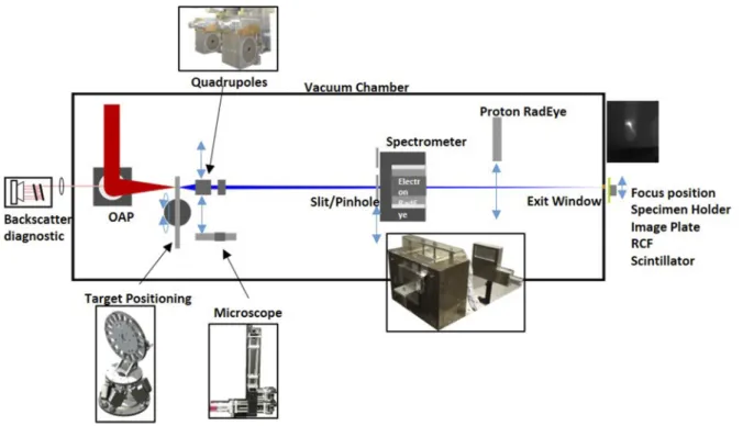
FIG. 1. Schematic of the experimental setup of the LION beamline in LEX-Photonics. The laser is focused with an off-axis parabolic mirror onto a thin foil hosted by the nano-foil target positioning system (nFTPS). A vacuum microscope ensures alignment with micrometer precision and is retracted thereafter. A permanent magnet quadrupole (PMQ) doublet can be inserted behind the target, and it transports the ions emitted from the laser-irradiated foil through a magnetic dipole field. This wide gap spectrometer serves also for analyzing the spectrum of emitted protons (in this case, without the PMQs) that are dispersed and registered with electronic CMOS RadEye detectors. Once optimized, the RadEye detectors are removed from the beam path, and the protons exit the vacuum chamber through a 50μm thin Kapton foil and reach the platform with the specimen.
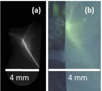
with quadrupoles to the application, we investigated additional diag- nostics for monitoring the laser–target interaction. Similar to the setup described in Bin et al.,14 the laser light scattered during the interaction with the target was, therefore, recollected by using the focusing off-axis parabolic (OAP) mirror, guided out of the vacuum, and refocused onto the chip of a CCD camera. A Fabry–Perot inter- ferometer, consisting of silver mirrors slightly tilted with respect to each other and each with a transmission of 10−3, was inserted a few cm before the focus. With every double pass through the inter- ferometer, a fraction of light was captured by using a camera. The tilt of the mirrors ensures that every replica reaches a different spot on the camera chip. At the same time, the effective light path length increases by approximately twice the separation distance for con- secutive replica. We typically observed five spots and adjusted the setup such that the central replica (i.e., the third) has a total path length that equals the focal length of the refocusing lens. If the tar- get is perfectly in focus of the OAP, this spot appears the smallest.
In addition, imperfect focusing or alignment of the target leads to different shapes of the replica (Fig. 2). Gaining quantitative infor- mation through this diagnostic is still under investigation and goes beyond the topics presented here. Nevertheless, by performing sev- eral shots with the primary ion and electron diagnostic in place, we could clearly observe a correlation that is worth studying further.
For our purpose, the image of this backscatter diagnostics yielded
sufficient information about each shot to classify it as good or bad, for example, when a target seemed broken or was not optimally posi- tioned. Although rather qualitative, we used this tool to estimate the number of successful shots per sample without direct observation of the protons. Poorly performing shots, for example, due to imper- fect plasma conditions, could be distinguished by a low amount of backscattered light from the plasma, by substantial shifts of the smallest replica or by unexpected deviations from their expected shapes.
FIG. 2. (a) Example image captured with the backscatter interferometer of good shot with the target in an ideal position and light focus in the third replica. (b) Example image of a bad shot with a previously damaged target and low proton yield.
FIG. 3. (a) Proton focus on an image plate outside the vacuum chamber. (b) Proton focus on the scintillator screen together with embryos.
Bunch transport and diagnostics
The abovementioned improvements in target repetition rate and ion characterization also enabled better understanding and adjustability of the ion bunch transport system.15A motorized per- manent magnet quadrupole (PMQ) doublet could be introduced into the beamline in order to collect and transport the protons emit- ted from the target. By adjusting the distances between the target and PMQs, we could tune the proton energy that is focused at a desired distance to the target. This energy is, in the following, referred to as design energy. The magnetic axis of the PMQs had been care- fully aligned to the laser axis by various offline field measurements and by cross-referencing the axis to a microscope image prior to
ysis, the slit of the wide angle spectrometer was exchanged with a 5 mm diameter pinhole through which the protons could enter the dipole field before reaching the RadEye detectors. This allowed for optimizing the transverse position of the PMQs to minimize steer- ing. Based on this direct feedback, the quadrupoles were positioned such that protons with the design energy of 7 MeV were focused to a spot outside of the vacuum chamber, at 1.53 m distance from the target. The exit window consisted of a 50μm thin Kapton foil.
Ion focus diagnostics and specimen positioning Image Plates (IP) were used to record the spatial distribution of protons behind the Kapton exit window.Figure 3(a) shows a typically measured distribution. The star shaped focus results from the broad energy distribution that is truncated and modified by the chromatic effect of the PMQs. The reproducible shape consisted of a long, thin, and intense central line and low intensity thin arms. The total length of the high fluence structure, which is of relevance for the studies described below, was roughly 5 mm at the exit window.
The fluence distribution is very inhomogeneous and localized with the highest fluence in the intersection of the long tail and the arms.
The peak proton fluence of a single proton bunch was evaluated via quantitative image plate analysis16and amounted to be in a range between 104protons/mm2and 106protons/mm2. The asymmetry of the shape suggests that the alignment of the quadrupoles can still be improved.
In three shots, we inserted gafchromic (EBT3) radiochromic films (RCF) at the position where, later on, the specimen was placed.
The films were evaluated with a flatbed scanner and an in-house developed Python code, using a multichannel film dosimetry algo- rithm. The applied dosimetry was qualitative in the sense that the films were calibrated previously with a 6 MeV photon beam from a conventional LINAC; thus, the obtained results inFig. 4represent photon equivalent doses.17 It is important to emphasize that this equivalent dose is not the real absorbed dose of the proton beam,
FIG. 4. Photon equivalent dose calculation from irradiated RCF films calibrated with a 6 MeV photon beam from a LINAC.
but related to the same chemical effect that would be induced by a photon beam on the film. This makes the calculated dose values hard to compare. However, this allows for a ballpark estimation of the dose regime, which was the purpose of this measurement. Also, the films allow assessing the spatial dose distribution. Qualitatively, the absorbed dose from the proton beam has a star-like shape as well, with a very heterogeneous dose distribution exhibiting a high- dose central region and a shallow background radiation dose of a few 100 s mGy. In the 0.15 mm2(0.25 mm of diameter) central part of the star-like shape, the induced change in the three measured films, rep- resenting Dmax, was in the range of 1.1–1.9 Gy/shot. Around Dmax, a steep dose gradient was detected resulting in only 50% of the Dmax
in 0.62 mm2(0.44 mm of radius), while the dose was reduced to 1%
of Dmaxwithin an area of 1.23 mm2.
Following this offline evaluation of proton focus and dose, the motorized specimen positioning system was inserted. It enabled positioning the specimen in both transverse dimensions. Position- ing along the beam direction was not crucial under the employed focusing geometry. In addition, a LANEX plastic scintillator screen, which lights up when hit by protons, could be inserted at the spec- imen position. A camera with large field of view overviewed the whole area. One additional close up camera with larger magnifica- tion served to mark the focus position on the camera image of the scintillation screen. This mark served as the reference for positioning the specimen in the same site after the scintillator had been par- tially moved to the side. Then, the close-up camera imaged both the scintillator and the embryos during the irradiation, as exemplarily shown inFig. 3(b).
Biological model and specimen setup
The complications that arose from experimenting within a radiation safety area, under non-sterile conditions, and uncertain- ties in timing of the experiment required a highly resilient, adaptable biological system. For the first irradiation of an organism with a laser-driven proton source at the LION beamline, we have intro- duced the zebrafish model, irradiating embryos of the size of 0.5–
1 mm. Zebrafish embryos have been selected because of their high tolerance to the environment and their small size corresponding to the size of a 3D cell culture model, providing an organism with functionally and morphologically highly similar organs to mam- malians (except lung). They have recently been introduced as a novel research model for various human diseases and treatments including cancer research, as they have many key genes involved in cell cycle, oncogenesis, tumor suppression, and DNA repair.18,19These small
Asian fishes can be rapidly bred in large numbers, and embryo devel- opment is extremely rapid during the first few days postfertilization (dpf) while the embryos and larvae are transparent, giving the pos- sibility to study thein vivoorgan development in the first postfertil- ization period (5 dpf) when no authority permission is required.20,21 These features make this animal model appropriate to investigate the effects of ionizing radiation at the macroscopic, microscopic, and molecular levels18providing an interim step between thein vitrocell culture and rodent systems. A major advantage of the embryos is that they can be positioned on the surface of water. For this, they are put in a thin film of water with a thickness not larger than the diame- ter of the embryos. This creates a relatively thin superficial biological target suited for irradiation with low energy charged particle beams, i.e., with low penetration depth.
The zebrafish (Danio rerio) strain (AB/Wt) is originated from the Department of Aquaculture, Szent István University, Gödöll˝o.
The study was performed under the permission of the animal well- being authority number: XXXII./1838/2015 applied for at the Uni- versity of Szeged. Adult fishes were put to breed in the late after- noon in breeding tanks, and the eggs were spawning the following morning at Szeged. Proper embryos were selected, sorted by micro- scopic observation, then washed in 10 cm Petri dishes, and put into aRanger MX45mobile incubator set to provide a normoxic con- dition at 28○C. After transportation to Munich 24 h postfertiliza- tion (hpf), choriated embryos of 0.5 mm diameter were treated with appropriate doses of protons.
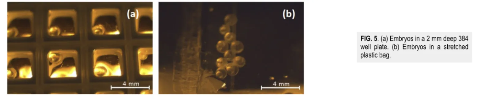
Two types of sample holders were used: a modified 96 well plate [Fig. 5(a)] and a frame (3.5×2.3 cm2) stretched plastic bag [Fig. 5(b)]. During the entire experiment, we paid particular atten- tion to how the fish embryos respond to the conditions of setups.
Therefore, it was an important aim to determine the most suitable life period of embryos and to test which kind of sample holder serves best for the experimental purposes. The special holders were man- ufactured at ELI-ALPS. Well plates with 384 wells down-sliced to 2 mm height contained 10μl water and 1 embryo. The plate could be fixed in the vertical position, for fixed horizontal beam irradi- ation. Due to the water surface tension, the embryos in each well could be positioned at the surface of the water, facing directly to the proton beam (without any extra material after the Kapton exit win- dow). The second sample holder was a framed, 30μm thin stretched plastic bag containing 10 embryos/bag, providing a high degree of sample position stability during the dose delivery. To maintain the living condition for the embryos, 1 ml water was given, building a thin layer of water only between the embryos and not in front of them. This setup is also appropriate for horizontal beam treatments.
FIG. 5. (a) Embryos in a 2 mm deep 384 well plate. (b) Embryos in a stretched plastic bag.
FIG. 6. [(a) and (c)] Non-irradiated control animals. [(b) and (d)] Animals with spine curvature and malformations in the length and eye size, furthermore, with yolk sac and pericardial edema. All images were taken 5 days postirradiation (dpi).
Assessment of morphology
The morphological abnormalities were assessed visually on individual embryos at 24-h intervals from the irradiation until 168 hpf after transportation to the zebrafish laboratory at Szeged.
The embryos were observed without any manipulation in place in the microplates and were incubated at 28○C. Viability was ana- lyzed with light transmission using a Zeiss Axio Imager Z1 light microscope (Zeiss EC Plan Neofluar 5×/0.16, 10×/0.3, 20×/0.5 M27, Germany) at 5×–20× magnification, and photomicrographs were taken using an AxioCam MR5 camera. The size and shape of the individual embryos, skull, spine, and tail and the development of the eyes were evaluated daily usingFiji—ImageJsoftware.
RESULTS
Irradiation experiment
We irradiated, in total, four bags and one modified 384 well plate with 32 wells of 3 × 3 × 2 mm3 occupied each with one embryo, i.e., 72 embryos. The irradiation of each sample (i.e., bag or individual well) consisted of a sequence of 20–60 laser shots deliv- ered on target with 0.5 Hz repetition rate. Thus, irradiation took 40–120 s/sample. Despite a shot-to-shot fluctuation11 in the pro- ton yield, the average particle number per irradiation was estimated to be within the same order of magnitude for the same number of shots.
The embryos were observed and video-documented during the delivery of the shots. This confirmed the embryonal movement within the chorions, while each capsule position was stably main- tained. Both arrangements were tested with the goal to know which method is optimal and tolerated best for this type of experiment.
Both the plastic bag (with the standard amount of water resulting in 1 mm water layer stretched equally in a rigid frame) and the spe- cial well plate proved to be well tolerated. The image guided method resulted in good superposition of dose delivery and individual single animals. The plastic bags proved to be easier to handle, for irradi- ation of the embryos with a uniform dose, but the more resource consuming separate irradiation in the well plate allows more precise individual evaluation of the radiation effects.
As zebrafish are being used more frequently in basic research, it is more and more apparent how flexible and tolerant to the unsteady surrounding conditions they are. The good portability of the system was fair enough on the 36 + 18 h of transport. 10 h were spent at
the laser facility, which was also well tolerated, as confirmed by the 97.66% survival of control lines with N = 84.
Irradiation response
Developmental malformations were observed for individual embryos. The relation between the proton focus size and the embryo size results in partial irradiation of each of the small animals with a localized, inhomogeneous dose. In the case of the plastic bag that contained many embryos, only one embryo per bag was positioned in the high dose region. Under these conditions, 18 out of the 72 embryos in the bags and the well plate showed reactions expressed by obvious malformations.
We measured and compared the length and eye-size of animals developing of irradiated embryos to the control animals (Fig. 6).
Irradiated animals exhibited changes in the length (due to spine cur- vature and developmental deterioration) and eye size; furthermore, edema of the yolk sac and pericardium as an acute reaction could be observed. Especially regarding changes in the eyes, it has to be emphasized that the observed alterations affected only one eye. We assume this asymmetry to be a result of the localized nature of the irradiation. In comparable experiments with homogeneously irradi- ated embryos, the change in the eye size was usually equal for both eyes. Due to both the low number of irradiated embryos and a lack of shot-to-shot dosimetry, a determination of the relation between the number of shots and occurrence of malformations was not pos- sible in this proof-of-principle experiment. However, the delivery of doses higher than 10 Gy photon equivalent dose could be confirmed by the morphological changes.
DISCUSSION AND CONCLUSIONS
Important technological advances and availability of the robust zebrafish embryo model have enabled living vertebrate organism irradiation with laser-driven proton bunches. It was possible to deliver a shot range from single proton bunches up to 60 bunches within about 2 min to individual embryos. In particular, creative approaches in sample preparation and handling were crucial for this multi-shot low energy irradiation. Aided by the water ten- sion, which held the embryos close to the surface, the protons pen- etrated through only 50 μm Kapton and some air before enter- ing the embryo. The focused proton bunches resulted in localized irradiation and partial body dose delivery. Biological evidence of
irradiation-related morphological damages was obtained. Despite the various limitations in current capability, these results on mor- phological changes provide proof for the delivery of a significant dose. In particular, the asymmetry in the malformations could hint to interesting biological effects.
Some key challenges must be overcome to make future exper- iments quantitatively meaningful. The uncertainty in single bunch dose monitoring has so far been too large for evaluating the dose dependence of biological endpoints. It represents, however, an inter- esting alternative to irradiation approaches, where a larger number of bunches with lower single bunch dose is applied. This conven- tional approach can mitigate the currently significant bunch-to- bunch fluctuations, but is counterproductive for high peak dose rate irradiation. However, reproducing the conventional irradiation con- dition using a laser based an ion source can benefit comparative studies. To achieve this, it would be also necessary to create a uni- form dose distribution in the focus area. Increasing the number of shots will also enable increasing the number of irradiated samples, for example, from 10 s to 1000 s of embryos, which remains relevant for gaining significant statistics on larger sample numbers.
For following the orthogonal direction of high single bunch doses, assessment of the single shot performance of the laser-driven ion source by complementary, ideally non-invasive measurements remains vital. The back reflected/scattered light showed definite cor- relations, and it remains to be studied in how far this approach can become a useful monitoring tool. In addition, the single bunch dose must be determined, ideally within the irradiated sample and with spatial resolution. Such an online, spatially resolved single bunch dosimetry is a most desirable tool. Then, the large shot-to-shot vari- ation of protons can become acceptable because the individual shots can be assessed with respect to the applied dose.
The proton energies of 7 MeV employed in this experiment constitute a compromise between sufficient energy and system sta- bility. The respective range in water is only 0.64 mm. Therefore, when irradiating the 0.5 mm diameter embryos, the Bragg peak was located inside the embryos. This constitutes additional uncertainty for dosimetry. One way to avoid this uncertainty could be to choose proton energies sufficiently high to penetrate the sample, as well as a dose detector placed on the back side of the sample. This is a widely accepted strategy for reducing errors. However, instead of avoiding the Bragg peak in the sample, in the future, efforts we will continue to gain control over the applied dose and the dosimetry in this situa- tion. This could be attractive, as it can open a possibility for studying the relative biological effectiveness (RBE) in the Bragg peak and its vicinity. The ideal dosimetry solution would yield more accurate information on the transverse and depth dose distribution inside the irradiated object. This will become particularly important for bio- logical experiments with larger organisms, where motion between subsequent bunches becomes relevant and could be achieved, for instance, by the measurement of the acoustic signal produced from the Bragg peak in water.22
With next generation laser systems that provide higher peak power, maximum ion energies will also increase. In our experiment, we operated close to this maximum energy of the exponential proton spectrum, which was 8 MeV. Therefore, the particle number fluctu- ations from shot to shot were rather large. Once larger maximum proton energies are available, an important strategic choice will be to operate the beamline in a stable way by performing experiments with
proton energies much lower than the respective endpoint energy of the spectrum.
It is also worth mentioning that the proton spot size can be manipulated much better by introducing a second pair of quadrupoles. For instance, this quadruplet can be used to achieve a more homogeneous dose distribution as performed by Pommarel et al.23who were able to produce a uniform spot with 15×25 mm2 dimensions. This method would open a wide range of applications in radiobiology and allow the comparison with established irradiation protocols.
As mentioned, our observations of partial malformations hint to possible localized radiobiological effects. We suppose that this was due to the steep dose gradient and the resulting partial irradiation of some embryos. The effects appeared even though we were yet unable to control the position, size, and total dose in the small embryo volume. We, therefore, see benefits in studying these local effects fur- ther, possibly by reducing the focus diameter to micrometer dimen- sions. This can also be achieved by introducing a second pair of quadrupoles. Together with the short bunch duration of the order of nanoseconds and below, this would enable very high peak dose rates and highly localized irradiation in microscopic areas. Thus, fast and potentially nonlinear processes that result from such close spacing of ion tracks in space and time become accessible. Studying them will require rethinking and identifying fast responding endpoints and even more precise in-sample micro-dosimetry. On the basis of previ- ous experiments,24we have already established reliable quantitative biological endpoints from evaluation of the macro-morphological and micro-morphological changes to study the radiation induced molecular processes. At the moment, we cannot assess the connec- tion of this radiation chemistry to the relevance for radiobiology.
However, with further technical developments allowing a better con- trol over the irradiation site in the target and opening the possi- bilities for micro beam irradiation schemes, the zebrafish embryo model may provide a useful tool for research on this connection in a vertebrate organism.
We will continue to develop this research line at the newly built Centre for Advanced Laser Applications (CALA) in Garching near Munich, which will offer the platform to perform these future appli- cation directed experiments on the basis of the upgraded ATLAS 3000 laser system. The experiences from the presented prototype experiments will provide valuable guidance for exploiting the tech- nological improvements and availability of larger proton energies for establishing a routine laser-driven ion source for these new kinds of explorative irradiation experiments.
AUTHORS’ CONTRIBUTIONS
J.S., K.P., and K.H. discussed and planned the study. D.H., C.K., T.M.O., J.B., and J.H. built the laser focusing and diagnostic setup. T.F.R. and P.H. constructed the quadrupole setup. Y.G. set up the target system. F.H.L. and F.S.E. assembled the ion diagnos- tic setup. D.H., J.B., J.H., T.F.R., M.S., Y.G., F.H.L., F.S.E., M.W., Z.S., E.R.S., and K.H. planned and conducted the experiment. A.A.F.
contributed to setting up of the biology platform. Z.S., E.R.S., and K.H. prepared and handled the zebrafish embryos during the trans- port and irradiation. T.T. and S.B. evaluated the biological results (malformations). R.P. evaluated the RCF films. D.T., J.B., and T.F.R.
evaluated the image plates. T.F.R., D.H., Z.S., and K.H. prepared the
the manuscript.
ACKNOWLEDGMENTS
This work was supported by the DFG Cluster of Excel- lence “Munich Centre for Advanced Photonics” (EXC 158). T.F.R.
acknowledges support from the German Academic Scholarship Foundation. F.H.L. acknowledges funding by BMBF under Contract No. 05P15WMEN9. The ELI-ALPS project (Grant No. GINOP- 2.3.6-15-2015-00001) is supported by the European Union and co- financed by the European Regional Development Fund. The project has received funding from the Laserlab-Europe V. project, H2020 research and innovation program under Grant Agreement No.
871124.
DATA AVAILABILITY
The data that support the findings of this study are available from the corresponding author upon reasonable request.
REFERENCES
1A. Higginson, R. J. Gray, M. King, R. J. Dance, S. D. R. Williamson, N. M. H.
Butler, R. Wilson, R. Capdessus, C. Armstrong, and J. S. Green,Nat. Commun.9, 724 (2018).
2A. Macchi, M. Borghesi, and M. Passoni,Rev. Mod. Phys.85, 751 (2013).
3S. D. Kraft, C. Richter, K. Zeil, M. Baumann, E. Beyreuther, S. Bock, M.
Bussmann, T. E. Cowan, Y. Dammene, W. Enghardt, U. Helbig, L. Karsch, T. Kluge, L. Laschinsky, E. Lessmann, J. Metzkes, D. Naumburger, R. Sauerbrey, M. Schürer, M. Sobiella, J. Woithe, U. Schramm, and J. Pawelke,New J. Phys.12, 085003 (2010).
4D. Doria, K. F. Kakolee, S. Kar, S. K. Litt, F. Fiorini, H. Ahmed, S. Green, J. C. G. Jeynes, J. Kavanagh, D. Kirby, K. J. Kirkby, C. L. Lewis, M. J. Merchant, G. Nersisyan, R. Prasad, K. M. Prise, G. Schettino, M. Zepf, and M. Borghesi,AIP Adv.2, 011209 (2012).
5K. Zeil, M. Baumann, E. Beyreuther, T. Burris-Mog, T. E. Cowan, W. Enghardt, L. Karsch, S. D. Kraft, L. Laschinsky, J. Metzkes, D. Naumburger, M. Oppelt, C. Richter, R. Sauerbrey, M. Schürer, U. Schramm, and J. Pawelke,Appl. Phys. B 110, 437 (2013).
6A. Yogo, T. Maeda, T. Hori, H. Sakaki, K. Ogura, M. Nishiuchi, A. Sagisaka, H. Kiriyama, H. Okada, S. Kanazawa, T. Shimomura, Y. Nakai, M. Tanoue, F. Sasao, P. R. Bolton, M. Murakami, T. Nomura, S. Kawanishi, and K. Kondo, Appl. Phys. Lett.98, 053701 (2011).
7A. Yogo, K. Sato, M. Nishikino, M. Mori, T. Teshima, H. Numasaki, M. Murakami, Y. Demizu, S. Akagi, S. Nagayama, K. Ogura, A. Sagisaka, S. Orimo, M. Nishiuchi, A. S. Pirozhkov, M. Ikegami, M. Tampo, H. Sakaki, M. Suzuki, I. Daito, Y. Oishi, H. Sugiyama, H. Kiriyama, H. Okada, S. Kanazawa, S. Kondo,
H. Daido,Appl. Phys. Lett.94, 181502 (2009).
8J. Bin, K. Allinger, W. Assmann, G. Dollinger, G. A. Drexler, A. A. Friedl, D. Habs, P. Hilz, R. Hoerlein, N. Humble, S. Karsch, K. Khrennikov, D. Kiefer, F. Krausz, W. Ma, D. Michalski, M. Molls, S. Raith, S. Reinhardt, B. Röper, T. E.
Schmid, T. Tajima, J. Wenz, O. Zlobinskaya, J. Schreiber, and J. J. Wilkens,Appl.
Phys. Lett.101, 243701 (2012).
9S. C. Wilks, A. B. Langdon, T. E. Cowan, M. Roth, M. Singh, S. Hatchett, M. H.
Key, D. Pennington, A. MacKinnon, and R. A. Snavely,Phys. Plasmas8, 542 (2001).
10C. Kreuzer, Technological Developments for Laser Ion Acceleration (LMU München, 2018).
11Y. Gao, J. Bin, D. Haffa, C. Kreuzer, J. Hartmann, M. Speicher, F. H. Lindner, T. M. Ostermayr, P. Hilz, T. F. Rösch, S. Lehrack, F. Englbrecht, S. Seuferling, M. Gilljohann, H. Ding, W. Ma, K. Parodi, and J. Schreiber,High Power Laser Sci.
Eng.5, e12 (2017).
12F. H. Lindner, J. H. Bin, F. Englbrecht, D. Haffa, P. R. Bolton, Y. Gao, J. Hartmann, P. Hilz, C. Kreuzer, T. M. Ostermayr, T. F. Rösch, M. Speicher, K. Parodi, P. G. Thirolf, and J. Schreiber, Rev. Sci. Instrum. 89, 013301 (2018).
13S. Reinhardt, W. Draxinger, J. Schreiber, and W. Assmann,J. Instrum.8, P03008 (2013).
14J. H. Bin, K. Allinger, K. Khrennikov, S. Karsch, P. R. Bolton, and J. Schreiber, Sci. Rep.7, 43548 (2017).
15T. F. Rösch, P. Hilz, J. Bin, F. Englbrecht, Y. Gao, D. Haffa, J. Hartmann, S. Herr, F. H. Lindner, M. Speicher, M. Würl, K. Parodi, and J. Schreiber,Curr.
Dir. Biomed. Eng.3, 339 (2017).
16S. Reinhardt,Detection of Laser-Accelerated Protons(Ludwig Maximilians Uni- versität München, 2012).
17S. Reinhardt, M. Hillbrand, J. Wilkens, W. Assmann, and K. Parodi,Med. Phys.
40, 215 (2013).
18E. R. Szabó, I. Plangár, T. T˝okés, I. Mán, R. Polanek, R. Kovács, G. Fekete, Z. Szabó, Z. Csenki, F. Baska, and K. Hideghéty,Zebrafish13, 481 (2016).
19M. F. McAleer, C. Davidson, W. R. Davidson, B. Yentzer, S. A. Farber, U. Rodeck, and A. P. Dicker,Int. J. Radiat. Oncol.61, 10 (2005).
20J. M. Bailey, B. A. Creamer, and M. A. Hollingsworth, Zebrafish 6, 329 (2009).
21G. A. Geiger, W. Fu, and G. D. Kao,Cancer Res.68, 3396 (2008).
22D. Haffa, R. Yang, J. Bin, S. Lehrack, F.-E. Brack, H. Ding, F. S. Englbrecht, Y. Gao, J. Gebhard, M. Gilljohann, J. Götzfried, J. Hartmann, S. Herr, P. Hilz, S. D. Kraft, C. Kreuzer, F. Kroll, F. H. Lindner, J. Metzkes-Ng, T. M. Ostermayr, E. Ridente, T. F. Rösch, G. Schilling, H.-P. Schlenvoigt, M. Speicher, D. Taray, M. Würl, K. Zeil, U. Schramm, S. Karsch, K. Parodi, P. R. Bolton, W. Assmann, and J. Schreiber,Sci. Rep.9, 6714 (2019).
23L. Pommarel, B. Vauzour, F. Mégnin-Chanet, E. Bayart, O. Delmas, F. Goudjil, C. Nauraye, V. Letellier, F. Pouzoulet, F. Schillaci, F. Romano, V. Scuderi, G. A. P.
Cirrone, E. Deutsch, A. Flacco, and V. Malka,Phys. Rev. Accel. Beams20, 032801 (2017).
24E. R. Szabó, M. Brand, S. Hans, K. Hideghéty, L. Karsch, E. Lessmann, J. Pawelke, M. Schürer, and E. Beyreuther,PLoS One13, e0206879 (2018).