Model analysis, Parameter Estimation and Control of a Synchronous
Generator
PhD thesis
Written by: Attila Fodor
Supervisors: Dr. Katalin Hangos, Dr. Attila Magyar
University of Pannonia
Doctoral School of Information Science and Technology 2015
DOI: 10.18136/PE.2015.583
Model analysis, Parameter Estimation and Control of a Synchronous Generator
Ertekez´´ es doktori (PhD) fokozat elnyer´ese ´erdek´eben a Pannon Egyetem Informatikai Tudom´anyok
Doktori Iskol´aj´ahoz tartoz´oan
´Irta:
Fodor Attila
Konzulens: Dr. Hangos Katalin, Dr. Magyar Attila Elfogad´asra javaslom (igen / nem)
(al´a´ır´as) A jel¨olt a doktori szigorlaton ...%-ot ´ert el
Veszpr´em ...
a Szigorlati Bizotts´ag eln¨oke Az ´ertekez´est b´ır´al´ok´ent elfogad´asra javaslom:
B´ır´al´o neve: ... (igen / nem)
(al´a´ır´as)
B´ır´al´o neve: ... (igen / nem)
(al´a´ır´as)
A jel¨olt az ´ertekez´es nyilv´anos vit´aj´an ...%-ot ´ert el
Veszpr´em, ...
a B´ır´al´o Bizotts´ag eln¨oke
A doktori (PhD) oklev´el min˝os´ıt´ese ...
...
Az EDHT eln¨oke
Contents
1 Introduction 9
1.1 Motivation and background . . . 9
1.2 Synchronous generators as dynamic systems and their control . . . . 10
1.2.1 SG modeling and analysis in the literature . . . 10
1.2.2 Generator controllers in the literature . . . 11
1.2.3 Controllers in nuclear power plants . . . 12
1.3 The power control problem in a pressurized water NPP . . . 13
1.3.1 The role of the SG in the plant technology . . . 13
1.3.2 The power control system . . . 13
1.3.3 Power changing operations . . . 14
1.4 Aim and structure of the thesis . . . 14
2 The synchronous generator model 17 2.1 The electrical submodel . . . 17
2.1.1 The flux linkage equations . . . 20
2.1.2 The voltage equations . . . 21
2.1.3 The dynamic model equations . . . 26
2.1.4 Connecting the synchronous generator to an infinitely large network . . . 26
2.2 The mechanical submodel . . . 28
2.3 The electro-mechanical state space model . . . 29
2.3.1 The state equations of the model . . . 30
2.3.2 The output equations of the model . . . 31
2.4 Model parameters . . . 31
3 Model analysis 34 3.1 Characterization of the nonlinear model . . . 34
3.2 The measurement methods in the Paks NPP . . . 34
3.3 Model verification through analysis of dynamic properties . . . 35
3.3.1 The dynamic model for verification . . . 35
3.3.2 The effect of changes in exciter voltage . . . 36
3.3.3 The effect of disturbances from the network . . . 37
3.3.4 Changing the active power of the generator . . . 38
3.3.5 Local stability analysis . . . 38
3.4 Sensitivity analysis for parameter estimation . . . 41
3.4.1 Frequently used methods in sensitivity analysis . . . 43
3.4.2 The dynamic model of the SG used for the analysis . . . 44
3.4.3 The aim and the method of the sensitivity analysis . . . 44
3.4.4 Results and conclusion of the sensitivity analysis . . . 45
3.5 Summary . . . 52
4 Parameter estimation 53 4.1 The measured signals and the estimation error function . . . 53
4.1.1 The estimation error . . . 54
4.1.2 Sensitivity of the estimation error function . . . 55
4.2 Generator parameters and initial values . . . 56
4.2.1 Choice of the base and normalized quantities . . . 56
4.2.2 Initial values of the parameters . . . 57
4.3 The parameter estimation method and error function minimization - APPS . . . 57
4.4 The quality of the estimated parameters . . . 61
4.4.1 Confidence regions in the parameter space . . . 61
4.4.2 The quality of the fit . . . 62
4.5 Summary . . . 68
5 Observer based LQ-servo control of the synchronous generator 69 5.1 The power control structure in MVM Paks NPP . . . 69
5.1.1 The existing controller structure . . . 69
5.1.2 Controller design specification . . . 70
5.2 The locally linearized model of the synchronous generator . . . 72
5.3 State observer design . . . 73
5.4 LQ servo controller design . . . 73
5.5 LQ servo controller verification . . . 75
5.5.1 Verification using step signals . . . 75
5.5.2 Verification using measured data . . . 76
5.6 Summary . . . 77
6 Conclusion and further work 78 6.1 New scientific results . . . 79
6.2 Further work . . . 80
6.3 Own Papers . . . 80
7 Appendix 83 7.1 Abbreviations . . . 83
7.2 Notation list . . . 83
Acknowledgement
The author of this dissertation wishes to acknowledge the continuous support and help of his supervisors, Prof. Katalin Hangos and Dr. Attila Magyar. I could not have accomplished this dissertation without their work and patience.
Furthermore, the author wishes to thank to the actual and the former teachers and colleagues in the Department of Electrical Engineering and Information Sys- tems and previously in Department of Automation for their continuous support and companionship.
Expressions of gratitude and apology are directed to my wife, my family and my colleagues and friends, who patiently endured the long working hours.
We acknowledge the financial support of this work by the Hungarian State and the European Union under the TAMOP-4.2.2.A-11/1/ KONV-2012-0072 project.
This work was also supported in part by the Hungarian Research Fund through grant 83440.
Abstract
Global warming caused by greenhouse gases and the constantly growing use of elec- tricity of the industry is forcing power plants operator’s engineers to achieve the higher efficiency of the power plants. In many cases, increasing the efficiency can be achieved by modernization of the control system, as it is done in the MVM Paks Nuclear Power Plant.
The dissertation deals with the synchronous generator used in nuclear power plants, thermal power plants and hydropower plants, presents the design of an ad- vanced controller for its power control together with the necessary preliminary steps.
The basis of the design is the state-space model of the synchronous generator.
Simple but effective model analysis methods were proposed for model verification and for preliminary parameter selection in parameter estimation of the synchronous generator. Based on the result of the sensitivity analysis, it is possible to define 4 groups of parameters. Based on this results 9 parameters were selected to parameter estimation.
A parameter estimation method using passive industrial measurement was also proposed for a synchronous generator that uses passive measurement of power chang- ing transients. The quality of the parameter estimation was characterized using the quality, the fit and the dependence of the error function on the parameters. The confidence region was also estimated from the level sets of the error function.
Based on the model and the parameter estimation a servo version of a Linear Quadratic Regulator (LQR) has been proposed for control of the industrial syn- chronous generator operating in MVM Paks NPP. The proposed LQ-servo controller was verified by simulation using step changes in active power. Based on the sim- ulation the developed LQ-servo controller provides better control than the existing PID controllers in MVM Paks NPP.
Abstract
Az ¨uvegh´azhat´as´u g´azok okozta glob´alis felmeleged´es ´es az ipar folyamatosan n¨ove- ked˝o villamos energiafelhaszn´al´asa arra k´enyszer´ıti az er˝om˝uveket ¨uzemeltet˝o m´er- n¨ok¨oket, hogy min´el nagyobb hat´asfokot pr´ob´aljanak el´erni az er˝om˝uvekben. A hat´asfok n¨ovel´es´et sok esetben az ir´any´ıt´astechnikai rendszer korszer˝us´ıt´es´evel is el lehet ´erni, mint ahogyan azt a MVM Paksi Atomer˝om˝uv´eben is teszik. A dolgo- zat az atom-, h˝o- ´es v´ızer˝om˝uvekben haszn´alt berendez´es, a szinkron gener´atorhoz haszn´alhat´o szab´alyoz´o tervez´es´et ´es annak l´ep´eseit mutatja be.
A kutat´asaim sor´an egy fizikai t¨orv´enyeken alapul´o ´allapott´er modellt haszn´al- tam. A modell anal´ızis egyszer˝u eszk¨ozeit haszn´alva elv´egeztem a szinkron gener´ator modellj´enek verifik´aci´oj´at ´es stabilit´as vizsg´alat´at. Elv´egeztem a modell param´etere- inek az ´erz´ekenys´egvizsg´alat´at, annak eredm´enyeit felhaszn´alva 4 csoportba soroltam a szinkron gener´ator modellj´enek a param´etereit. Ezeket felhaszn´alva a param´eterek k¨oz¨ul meghat´aroztam azokat a param´etereket, amelyeket becs¨ulni lehet.
Passz´ıv ipari m´er´esek alapj´an elv´egeztem a MVM Paksi Atomer˝om˝u egyik szink- ron gener´ator´anak a param´eterbecsl´es´et terhel´esi tranziens felhaszn´al´as´aval. A pa- ram´eterbecsl´es j´os´ag´at ellen˝oriztem az illeszked´es ´es a param´eterek f¨uggv´eny´eben is, k¨ozel´ıt˝o konfidencia intervallumokat hat´aroztam meg a hibaf¨uggv´eny szinthalmaza- ib´ol.
A modellt ´es a becs¨ult param´etereket felhaszn´alva egy observer alap´u LQ-servo (Linear Quadratic) szab´alyoz´ot terveztem a Paksi Atomer˝om˝u gener´ator´ahoz. A megtervezett szab´alyoz´o stabilit´as´at szimul´ac´okkal ellen˝oriztem. A szimul´aci´ok alap- j´an a megtervezett ´uj LQ-servo szab´alyoz´o jobb szab´alyoz´asra k´epes, mint a jelenleg haszn´alt PID szab´alyoz´ok.
Abstrakt
Ingenieure, die Kraftwerke betreiben, werden durch die globale Erw¨armung, die we- gen der Treibhausgase und des st¨andig wachsenden Stromverbrauchs in der Industrie entsteht, gezwungen, h¨ohere Effizienz der Kraftwerke zu erreichen. Die Effizien- zerh¨ohung kann in vielen F¨allen durch die Modernisierung der Prozessleittechnik erreicht werden, wie das in MVM Kernkraftwerk Paks getan wird.
Die Dissertation zeigt die Ausr¨ustung, die in Kern-, Heiz- und Wasserkraftwerken verwendet wird, bzw. die Schritte der Systemplanung eines Regulators, welcher zu den Synchrongeneratoren gebraucht werden kann. W¨ahrend meiner Forschungen wurde ein Zustandsraummodell verwendet, das auf physischen Gesetzen basierte.
Die Verifikation des Synchrongenerators und die Stabilit¨atsuntersuchung wurden durch die einfachen Methoden der Modellanalyse durchgef¨uhrt.
Nachdem die Sensitivit¨atsanalyse durchgef¨uhrt worden war, ließen sich anhand deren Ergebnisse 4 Parametergruppen des Synchrongenerators definieren. Mit dieser Methode wurden die messbaren Parameter bestimmt. Die Parametersch¨atzung eines Synchrongenerators wurde durch passive Industriemessungen im Kernkraftwerk Paks mit Verwendung Belastungstransienten durchgef¨uhrt. Die Qualit¨at der Parameter- sch¨atzung wurde auch in der Funktion der Passung und der Parameter kontrolliert.
Ann¨ahernde konfidentielle Intervalle wurden aus den Niveaumengen der Fehlerfunk- tion definiert.
Ein LQ-Servo-Regulator (Linear Quadratic) wurde mit Hilfe des Modells und der gesch¨atzten Parameter zum Atomkraftwerksgenerator geplant. Die Stabilit¨at des ge- planten Regulators wurde durch die Simulationstechnik kontrolliert. Der entwickelte LQ-Servo-Regulator erm¨oglicht aufgrund der Simulationen bessere Regelungen als die vorhandenen PID-Regler.
Chapter 1 Introduction
1.1 Motivation and background
Mankind wanted to use the possibility of the rotation long-long time ago, using the technical advancement of the age. An example of this is the wheel, the horse-mill of the antiquity and other applications (see: [69] and [15]). The rotating actuation can be easily applied using electricity in the rotating electrical machines (e.g.: induction machine, synchronous machine, direct-current machine). This principle is used even today for the electrical generators in power plants [47].
Rotating electrical machines, electrical motors and generators form a basic class of units in electrical engineering, and present a challenge in control-oriented appli- cations because of their inherent nonlinearities. Although control-related methods, such as dynamic modeling, model analysis, parameter estimation, controller design and diagnosis is a traditional and well investigated area in both the classical linear and the advanced nonlinear systems and control theory, but these challenges and the practical importance of the electrical rotating machines call for a continuous advancing of their control using the recent results in systems and control theory (see e.g. [38], [39] and [40]).
This work is focused a class of rotating electrical machines, the so called syn- chronous machines, where both the synchronous motors and generators are of great practical importance. A number of fundamental books and papers deal with the control problems of induction motors (see e.g. [90], [93] and [94]), but the modeling, model analysis and control design problems of synchronous generators are much less investigated, maybe because of their restricted application area. These generators are widely used in industrial power plants, where the safety-critical nature of their operation makes the use of advanced control approaches difficult, and thus very rare.
Unfortunately, the use of advanced control methods for a nonlinear system (see e.g. [38] and [9]) requires the effective utilization of the specialities of the system to be controlled and that of the control task, otherwise the general purpose methods lead to infeasible or practically intractable problems. Therefore, an interdisciplinary holistic approach was adopted to carry out the model analysis, parameter estima- tion and controller design of an industrial synchronous generator to overcome this obstacle.
Beside of the traditional, well-established and robust linear controller design pre-
sented in this thesis, the first steps to explore the applicability of advanced nonlinear techniques have also been made in a follow-up research [O7].
1.2 Synchronous generators as dynamic systems and their control
Nuclear power plants are important energy providers worldwide. They produce energy mainly in the form of electrical energy, the transportation and distribution of which is performed by using large-scale electrical power grid. This grid should be operated in a balanced way taking the time varying power demand of the consumers into account. From the viewpoint of the power grid the electric power generation of nuclear power is characterized by the operation of the electrical generators.
It is obvious, since the final stage of the power production in a nuclear power plant (NPP) includes a synchronous generator (SG) that is driven by a turbine. A synchronous generator operating in a NPP and its controller is the subject of the present thesis.
Besides the active power produced by a power plant, other characteristics are also of great importance. Most notably the reactive power and the frequency of the produced energy are also essential. The importance of the reactive power is indicated by the fact that insufficient reactive power of the system may result in voltage collapse. Therefore, it is widely accepted that the consumers of the reactive power should pay for it and the producers of the reactive power are enumerated [29]. Therefore, the power controllers of nuclear power plants should also take the production of the reactive power into account.
Because of the above described requirements on the operation of the large-scale electrical power grids, power plants should not only be able to follow the time-varying active and reactive power demand of the consumers and the central dispatch center, but also keep the quality indicators (frequency, waveform, total harmonic distortion) of the grid on the expected level. This can be achieved by applying proper control methods based on dynamic models of plant (see e.g. [11], [56]) and the involved generators.
1.2.1 SG modeling and analysis in the literature
Because of the specialities and great practical importance of synchronous genera- tors in power plants, their modeling for control purposes is well investigated in the literature. Besides of the basic textbooks (see e.g. [7]) that develop general purpose dynamic models for SGs, there are several papers that describe the modeling and use the developed models for the design of various controllers, see e.g. [55, 25].
Two SG models are presented and analyzed in [13]. One model is developed in the (d, q) natural reference frame and the other one is referred to the (d, q) stator reference frame. The models are validated using a 75 kVA salient-pole synchronous machine with damper windings. In [66] a new method of SG modeling is presented taking an infinite inner resistance into account, and a statistical technique for de- termining the parameters of the synchronous machine is proposed.
The SG models in [97], [98], [65], [26] are linear models, which do not consider the mechanical motion equation. This implies that they do not describe neither the rotor position nor the loading angle (δ). However, the loading angle is important system variable because the SG may fall out of sync if the loading angle exceeds 90o.
A simplified linear mathematical model of a SG with an excitation system is pre- sented in [64], and the stability of the model is investigated by simulation. Angular velocity of the machine is assumed to be constant in this model, hence it is not able to calculate the load angle (δ).
A suitable method for time-domain identification of the parameters of a labora- tory size synchronous machine (380 V, 3 kVA) is presented in [97] that uses a hybrid state space model. The angular velocity of the SG has been fixed to the synchronous speed in the model. A load rejection test of a combined resistive/inductive load is performed for the parameter identification.
Because of the highly nonlinear nature of the dynamic models of synchronous machines, the need for applying methods of modern systems and control theory have also appeared in the literature recently.
In [98] a simple linear time-invariant state space model of a SG is developed for load-rejection tests and the model was tested in a laboratory size generator (1.5 kVA).
A third order nonlinear state space model of a synchronous generator has also been proposed in [27], where field voltage was considered as input, active output power and rotor angle were considered as outputs.
A square-root unscented Kalman filter has been applied recently to simulta- neously estimate state variables and unknown generator parameters in [45]. Here a third order model with field voltage input has been considered that has been equipped with suitable measurement and output equations.
1.2.2 Generator controllers in the literature
Several excellent books were fully devoted to the control of induction motors (IM) (see. e.g.: [90], [91], [94] and [93]). The modeling, stability and the control of the synchronous generator is a less investigated area than the induction motor because of its limited use.
Third-order nonlinear models are commonly used in control theory for the sta- bility analysis of both open loop and closed loop synchronous machines (SM). The ability of these models to describe the electrical machine dynamics has been tested experimentally in [8] using a 7 kVA lab-scale SG.
In addition to conventional control tasks related to synchronous generators in power plants, special purpose SG control studies are also reported. The behavior of a SG during short-circuit is investigated in [30]. This article reports the short- circuit characteristics of a stand-alone turbo-generator driven by separately excited DC motors, the applied model of the SG is similar to that used in this paper.
A sliding mode controller is proposed in [88] using a non-linear SG model, where the stability of the controlled model is also analyzed.
A new approach to SG output voltage control is presented in [65] applying H∞
control theory, where the control strategy was based on the classical modeling of the SG. A technique to determine the effect of the field-voltage circuit during the load-rejection test of a large-rating salient-pole SG was presented in [26].
The presence of reactive power may cause overload effects on the line, circuit breakers, transformers, relays, but it cannot be transformed into mechanical power.
In addition, the presence of reactive power requires to increase the dimension of cables used in the transmission line. Therefore the management of reactive power generation and consumption is well investigated in the literature. A recent paper [23] proposes reactive power compensation using a fuzzy logic controlled synchronous machine. Reactive power management is also a critical issue when dealing with the planning and operation of power networks. Its use for transmission line fault location and power system protection is described in [103].
A recent study [5] proposes a coordinated reactive power planning strategy among induction generators. According to this strategy, the total reactive power capability is obtained first and the limitations on deliverable power are deduced from it for each operation point.
An optimal reactive power flow incorporating static voltage stability is computed in [102] based on a multi-objective adaptive immune algorithm. The algorithm solves the optimal reactive power flow problem incorporating voltage stability.
In a power system, voltage stability margin improvement can and should also be done by regulating generator voltages, transformer tap settings and capacitor or reactor rated reactive powers. For this purpose, a reactive power rescheduling method with generator ranking has been proposed in [78].
Seen from a holistic view, electrical power systems should operate in an economic way with minimum possible operating cost and under normal operating conditions.
To ensure this, a preventive controller for power systems has been presented in [96].
It encompasses many types of control actions, including generation rescheduling, load curtailment and network switching reactive compensation.
1.2.3 Controllers in nuclear power plants
Interesting advanced control applications can also be found in nuclear power plants.
A robust strategy to cascade control of a TOPAZ II nuclear system has been pre- sented in [4]. The control strategy is based on linearizing feedback control endowed with a modeling error estimator via a reduced order observer. The proposed strat- egy results in a control scheme which comprises a cascade approach. In the start-up regime this cascade operates two loops of control.
In [19], a MIMO reactor controller has been presented using soft computing methods. An on-line intelligent core controller for load following operations has been designed in this paper, based on a heuristic control algorithm, using a valid and updatable recurrent neutral network.
In [86], the performance of some control strategies for a power manoeuvering event was evaluated. The reactor-leading strategy showed a relatively weak perfor- mance although the reactor power followed the external power demand well. The turbine-leading strategy, that is widely used for commercial nuclear power plants, concluded to be still adoptable for a power control strategy.
1.3 The power control problem in a pressurized water NPP
MVM Paks NPP, where the investigated generators work, is located in Hungary, and operates four pressurized water (VVER-440/213 type) reactors with a total nominal electrical power of 2000 MW (see. [2]). Each reactor is equipped with two turbine- generator units that work in parallel. The turbo generator is a specific synchronous generator with a special cooling system.
Our study is concerned with the power control of MVM Paks NPP. In this section a brief overview of the plant from the generators point of view is given first, then a description of the power changing operations follows.
1.3.1 The role of the SG in the plant technology
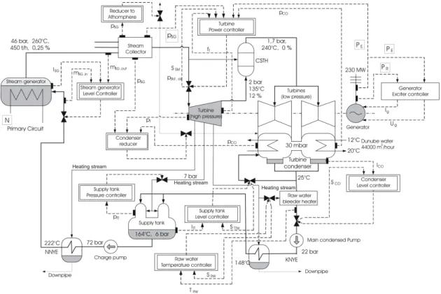
The SG is located in the secondary circuit of a unit in MVM Paks NPP (see Fig.
1 for the flowchart the secondary circuit). Every nuclear unit operates six steam generators with capacity 450 t/h with a temperature of 260◦C and a pressure of 46 bar that interface the primary and secondary circuits [80], [31], [46]. These six steam generators are connected to two turbo-generators, three to each.
Every nuclear unit operates two independent secondary coolant circuits, that are controlled by independent control systems. In the first stage of the secondary coolant circuit there are three steam generators that provide steam for the turbines. There are three turbines in each secondary coolant circuit (one high pressure and two low pressure ones), attached to one synchronous generator and one exciter machine set on the same axis.
1.3.2 The power control system
The power control of a unit in MVM Paks NPP is performed by three loosely coupled controllers: the power controller of the reactor, the turbine power controller and the generator exciter controller. While the reactor power controller is mainly responsible for taking care of the total power, the turbine controller regulates the frequency and the generator controller deals with maintaining the proper ratio of the active and reactive power.
The detailed model-based analysis of the reactor power controller of a unit in MVM Paks NPP is reported in [35], that uses a simple dynamic model of the primary circuit based on first engineering principles.
As the generator controller operates relatively independently of the other two controllers involved in the power control, we aim at optimally re-design the generator controller using a simple control-oriented dynamic model in order to be able to maintain the desired active and reactive power level even under power changing operation conditions.
Figure 1: The schematic figure of the secondary circuit. Both the main operating units and the main controllers are shown.
1.3.3 Power changing operations
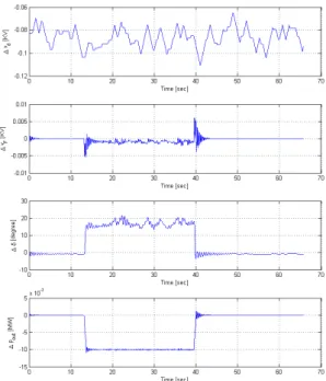
In Figure 2 the time varying output of a nuclear power plant, MVM Paks NPP is depicted during load changing transients. It can be seen that the reactive power (qout) is also changing in the same way as the active power (pout). Since a unit in the NPP of interest contains two generators, the same signals belonging to the two generators are both depicted.
It can be seen in Figure 2 that the reactive powers (qout) of the SG are changing during the power switching. It can also be seen that the active power (pout) of the generators follow the neutron flux which follows the control rod position of the nuclear reactor.
In the case presented by Figure 2 the active power was controlled by a classical PI controller with the manipulated input being the exciter voltage (vF). On the other hand, no reactive power control policy was used in the NPP, therefore the reactive power follows the change of the active power.
1.4 Aim and structure of the thesis
The literature about synchronous generator control (see the first part of Section 1.2), however, does not take the special circumstances found in nuclear power plants into account, where load torque and exciter current are the measurable input variables (although load torque is only measured indirectly through the turbine steam load), and the important measurable output variables are the active and reactive power.
Synchronous generator#1 Synchronous generator#2
Primary circuit
0 0.5 1 1.5 2 2.5
·104 2.2
2.4 2.6
·108
time [s]
pout[W]
0 0.5 1 1.5 2 2.5
·104 2.2
2.4 2.6
·108
time [s]
pout[W]
0 0.5 1 1.5 2 2.5
·104
−3
−2
−1 0 ·107
time [s]
qout[VA]
0 0.5 1 1.5 2 2.5
·104
−3
−2
−1 0 ·107
time [s]
qout[VA]
0 0.5 1 1.5 2 2.5
·104 1
1.05 1.1 1.15 1.2
time [s]
iF[kA]
0 0.5 1 1.5 2 2.5
·104 1
1.05 1.1 1.15 1.2
time [s]
iF[kA]
0 0.5 1 1.5 2 2.5
·104 95
100 105 110
time [s]
Reactorneutronflux
0 0.5 1 1.5 2 2.5
·104 180
200 220 240
time [s]
Controlrodposition
Figure 2: Effective and reactive power (pout and qout) and the exiting current (iF) of two generators attached to the same reactor, the neutron flux and control rod posi- tion of the reactor during load changing transients. The close connection between the neutron flux andpout is apparent. Because of the simple controller structure qout followspout.
In addition, these papers do not describe the mechanical motion related to the SG, thus there is no possibility to give any information about the angular velocity and the loading angle, that are important state variables under industrial operating con- ditions. These facts require to develop special dynamic models for large industrial synchronous generators operating in nuclear power plants. Based on these models, model-based re-design of the generator controller can be applied so that it is able to control the active and reactive power of the power plant simultaneously. For con- troller design, however, the developed model should be verified against engineering intuition and its parameters estimated using measured data from the real power plant.
The first step of this work was to propose a simple dynamic model of a SG in a nuclear power plant for control studies (see Chapter 2), where the model develop- ment is largely based on [7], [6] and [17]. This chapter contains also the description and initial values of the parameters of the model.
Chapter 3 shows the model verification, as well as the methods and the results of the parametric sensitivity analysis (see Chapter 3). Based on the result of the sensi- tivity analysis, the parameters to be estimated could be determined. The sensitivity analysis was thus a preparatory step for the model parameter estimation.
In Chapter 4, an optimization-based method is proposed for estimating the model parameters from industrial measured data.
The final aim of this work was to design a MIMO servo controller that keeps the active power of a SG at the desired level, and performs reactive power reference tracking using the reactive power demand from the central dispatch center. The controller design and verification is described in Chapter 5.
Finally, the conclusion and the further work are presented in Chapter 6. This chapter summarizes the results, contains the list of own publications, and the thesis points.
The appendix of the dissertation contains the list of abbreviations and notations.
Chapter 2
The synchronous generator model
In this chapter the state-space model for a synchronous generator is described that will be used for stability analysis, parameter estimation and controller design.
The model development is largely based on [7], [6] and [17] but the special circumstances of the generator operation in the considered nuclear power plant have also been taken into account.
There are several synchronous machine (SM) models in the literature (e.g.:
Coultes and Watson [24], Wamkeue at al. [99], [97] and [98], Loukianov at al.
[55], Dehkordi at al. [28], Semlyen et al. [85], Mouni at al. [66] and [65], Tu et al. [89], Achilles et al. [3], Hansen et al. [42], Ramtharan et al. [77], Milano [62], Perdana [71], Gonzalez-Longatt et al. [36], Dehghani [27], Nanou et al. [67] ) but the special requirements (the presence of active and reactive power equations the need for modeling amortisseur or dumper windings) called for an extension of the usual models. There are a few extended dynamics model in the literature [7], [6], [55], that required further improvements and classification.
It is important to note, however, that large industrial synchronous generators operating in other (e.g. hydro, gas or coal powered) types of power plant have similar operating conditions and grid requirements, therefore the resulting dynamical model is also applicable there.
Only the basic steps of the model development and the resulting model equations are described here using the notation list can be found in the Appendix (see Section 7.2).
2.1 The electrical submodel
For constructing the synchronous generator model, the following assumptions are made:
1. a symmetric tri-phase stator winding system in machine is assumed, 2. the machine has one field coil,
3. there are two amortisseur or damper windings in the machine, 4. all of the windings are magnetically coupled,
5. the flux linkage of the winding is the function of the rotor position,
6. the spatial distribution of the stator fluxes and apertures wave are considered to be sinusoidal,
7. stator and rotor permeability are assumed to be infinite
8. all the losses due to wiring, saturation, and slots can be neglected.
According to assumptions 4. and 5. the actual terminal voltagev of the windings can be written in the form
v =± XJ
j=1
(rjij)± XJ
j=1
( ˙λj), (1)
whereij are the currents,rj are the winding resistances, andλj are the flux linkages.
The positive directions of the stator currents point out of the synchronous generator terminals.
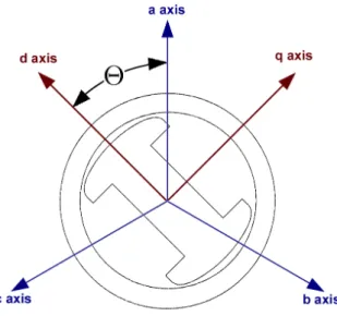
Thereafter, the two stator electromagnetic fields, both traveling at rotor speed, were identified by decomposing each stator phase current under steady state into two components, one in phase with the electromagnetic field and the other phase shifted by 90o. With the aboves, one can construct an airgap field with its maximum aligned to the rotor poles (d axis), while the other is aligned to the q axis (between poles).
Figure 3: The abc and 0dq frames of the generator. The 0dq coordinate of frame is fixed to the rotor, abc coordinate frame is fixed the stator flux.
This change in the coordinates is called the Park’s transformation [70] that gives id= 2
3
iacos(Θ) +ibcos
Θ− 2π 3
+iccos
Θ−4π 3
(2) iq = 2
3
iasin(Θ) +ibsin
Θ− 2π 3
+icsin
Θ−4π 3
, (3)
where ia, ib and ic are the phase currents and Θ is the angle between the phase currentiaand the currentid. During the eduction the angles are computed in radian.
The Park’s transformation uses three variables as d and q axis components (id and iq) and the last one is the stationary current component (i0), which is proportional to the zero-sequence current. By denoting vectors by boldface and matrices with capital boldface letters can write the new current components from the relationship i0dq =P iabc, (4) where the current vectors are
i0dq =
i0 id iq T
and iabc=
ia ib ic T
, (5)
and the Park’s transformation matrix is P =
r2 3
√1 2
√1 2
√1 2
cos(Θ) cos(Θ− 2π3 ) cos(Θ− 4π3 ) sin(Θ) sin(Θ− 2π3 ) sin(Θ−4π3 )
. (6)
All flux components correspond to an electromagnetic field (EMF), the generator EMF is primarily along the rotorqaxis. The angle between this EMF and the output voltage is the machine torque angle δ, where the phase a is the reference voltage of the output voltage. The angular position of the d axis (in radian) is in the form
Θ =ωrt+δ+π/2, (7)
where ωr is the rated synchronous angular frequency. Finally, the following voltage and linkage equations can be written
v0dq =P vabc and λ0dq =P λabc, (8) where the voltage vectors v0dq =
v0 vd vq T
and vabc =
va vb vc T
, and the linkage flux vectors λ0dq =
λ0 λd λq T
and λabc =
λa λb λc T
are constructed similarly to (5).
There exists also an inverse of the Park’s transformation matrix (6) that is used to obtain
iabc =P−1i0dq. (9) Finally, the the following active power equations can be obtained:
p=vaia+vbib+vcic=vTabciabc= (P−1v0dq)T (P−1i0dq) =
=vT0dq(P−1)T P−1i0dq =vT0dqP P−1i0dq =vT0dqi0dq =
=vdid+vqiq+v0i0 (10)
2.1.1 The flux linkage equations
The generator consists of six coupled coils. The coils with indices a, b and c are the stator phases coils,F is the field coil, D is the d-axis amortisseur and Q is the q-axis amortisseur. The linkage equations can be written in the following form
λa λb λc λF λD λQ
=
Laa Lab Lac LaF LaD LaQ Lba Lbb Lbc LbF LbD LbQ Lca Lcb Lcc LcF LcD LcQ LF a LF b LF c LF F LF D LF Q LDa LDb LDc LDF LDD LDQ LQa LQb LQc LQF LQD LQQ
ia ib ic iF iD iQ
=
Lss LsR
LRs LRR
iabc
iF DQ
,
(11) whereLxy is the coupling inductance of the coilsxandy,LRR is the rotor-rotor, Lss
is the stator-stator, LsR and LRs are the stator-rotor inductances. It is important to note that the inductances are time varying since Θ is a function of time.
The stator self inductances are given by Laa =Ls+Lmcos(2Θ) Lbb=Ls+Lmcos(2(Θ−2π3 )) Lcc=Ls+Lmcos(2(Θ + 2π3 )),
(12) where Ls is the self inductance and Lm is the mutual inductance.
The rotor self inductances are written as: LF F = LF and LDD = LD and LQQ=LQ.
The stator mutual inductances are given by
Lab =Lba =−Ms−Lmcos(2(Θ− π6)) Lbc =Lcb =−Ms−Lmcos(2(Θ−π2)) Lca =Lac =−Ms−Lmcos(2(Θ + 5π6 )),
(13) where Ms and Lm is mutual inductances.
The rotor mutual inductances are LF D =LDF =MR and LF Q = LQF = 0 and LDQ=LQD = 0.
The stator to rotor mutual inductances are given by: (From phase windings to the field windings)
LaF =LF a=MF cos(Θ) LbF =LF b =MFcos(Θ− 2π3 ) LcF =LF c =MFcos(Θ + 2π3 )
(14) The stator to rotor mutual inductances are given by: (From phase windings to the damper windings direct axis)
LaD =LDa=MDcos(Θ) LbD =LDb =MDcos(Θ−2π3 ) LcD =LDc =MDcos(Θ +2π3 )
(15) The stator to rotor mutual inductances are given by: (From phase windings to the damper quadrature direct axis)
LaQ =LQa =MQcos(Θ) LbQ =LQb =MQcos(Θ−2π3 ) LcQ =LQc =MQcos(Θ +2π3 )
(16)
The time-varying inductances can be simplified by referring all quantities to a rotor frame of reference through Park’s Transformation:
P 0 0 I3
λabc
λF DQ
=
P 0 0 I3
Lss LsR
LRs LRR
·
·
P−1 0 0 I3
P 0 0 I3
iabc
iF DQ
(17) The matrixP is the Park’s transformation matrix in (6),I3 is the 3×3 unit matrix and λF DQ=
λF λD λQ T
. This way, we obtain the following transformed flux linkage equations
λ0 λd λq λF λD λQ
=
L0 0 0 0 0 0
0 Ld 0 kMF kMD 0
0 0 Lq 0 0 kMQ
0 kMF 0 LF MR 0
0 kMD 0 MR LD 0
0 0 kMQ 0 0 LQ
i0 id iq iF iD iQ
, (18)
where the new constants are defined by the following equations:
Ld=Ls+Ms+ 32Lm Lq=Ls+Ms− 32Lm L0 =Ls−2Ms k=
q2 3
(19)
2.1.2 The voltage equations
The equivalent circuit of the synchronous machine is depicted in Figure 4.
Figure 4: The simplified equivalent circuit of the stator and rotor circuits. The voltagesvD and vQ are zero, because the ammortisseur windings are short-circuited.
Using the notations of Figure 4 the general matrix-vector form of Kirchoff’s voltage law is
v =−ri−λ˙ +vn, (20) and its particular form is
vabc
vF DQ
=−
Rabc 0 0 RF DQ
iabc
iF DQ
−
λ˙abc
λF DQ˙
+ vn
0
, (21)
where vF DQ = [vF vD vQ], iF DQ = [iF iD iQ], Rabc =
ra 0 0 0 rb 0 0 0 rc
and
RF DQ=
rF 0 0 0 rD 0 0 0 rQ
.
In what follows, the voltage equations will be expressed in the dq coordinate system. Expanding Eq. (21) leads to the matrix equation
va vb vc
−vF 0 0
=−
ra 0 0 0 0 0
0 rb 0 0 0 0
0 0 rc 0 0 0
0 0 0 rF 0 0
0 0 0 0 rD 0
0 0 0 0 0 rQ
ia ib ic iF iD iQ
−
λ˙a λ˙b
λ˙c λ˙F λ˙D λ˙Q
+
vn
0
(22)
where the vn is the neutral voltage vn =−rn
1 1 1 1 1 1 1 1 1
ia ib ic
−Ln
1 1 1 1 1 1 1 1 1
i˙a i˙b i˙c
(23)
vn =−Rniabc−Lnmi˙abc (24) where Lnm =
Ln Ln Ln
Ln Ln Ln Ln Ln Ln
and Rn =
rn rn rn
rn rn rn rn rn rn
.
Transforming the left hand side of Eq. (21) to the dq frame is done with Park’s
transformation:
P 0 0 I3
vabc
vF DQ
=
v0dq
vF DQ
(25) The first step is to express the voltage of the resistances in the d-q frame using Ohm’s law.
P 0 0 I3
Rabc 0 0 RF DQ
iabc
iF DQ
=
=
P 0 0 I3
Rabc 0 0 RF DQ
P−1 0 0 I3
P 0 0 I3
iabc
iF DQ
=
=
P RabcP−1 0 0 RF DQ
i0dq
iF DQ
=
Rˆabc 0 0 RF DQ
i0dq
iF DQ
(26)
Figure 5: The simplified equivalent circuit of the transformed stator and rotor cir- cuits
As it was assumed, the machine has symmetrical tri-phase stator windings (ra = rb =rc =r), so the resistance matrixRˆabc is in the following diagonal form:
Rˆabc =Rabc=
r 0 0 0 r 0 0 0 r
(27)
The second step is to compute the time derivatives of the fluxes as P 0
0 I3
λ˙abc
λ˙F DQ
=
Pλ˙abc
λ˙F DQ
. (28)
Using the fact, that P is time dependent (through Θ), Pλ˙abc can be expressed as:
Pλ˙abc=λ˙0dq −P λ˙ abc =λ˙0dq−P P˙ −1λ0dq (29) It is easy to see from Eq. (29), that expressionP P˙ −1λ0dq has the following form:
P P˙ −1λ0dq =ω
0 0 0 0 0 −1
0 1 0
λ0 λd λq
=
0
−ωλq ωλd
(30)
The final step is to obtain the neutral voltage of Eq. (24) using Park’s transfor- mation
v0dq =P vn=−P RnP−1P iabc−P LnmP−1Pi˙abc =
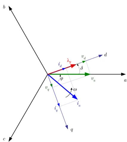
Figure 6: The voltages, currents and the flux of the synchronous machine in abc and dq coordinate system, where ϕ is the phase offset, δ is the load angle and ω represents the angular velocity of the EMF.
−P RnP−1i0dq−P LnmP−1i˙0dq =
−3rni0 0 0
−
−3Lni˙0 0 0
. (31) Summarizing the previous steps, the voltage equations can be expressed in the dq frame as
v0dq
vF DQ
=−
R0dq 0 0 RF DQ
i0dq
iF DQ
−
λ˙0dq
λ˙F DQ
+
P P˙ −1λ0dq 0
+
v0dq
0
, (32) wheren0dq is the voltage drop from the neutral network andωis the angular velocity.
Using Eq. (18) and (32) the voltage equations can be rearranged in the form:
v0 vd vF vD = 0
vq vQ = 0
=−
r+ 3rn 0 0 0 0 0
0 r 0 0 ωLq ωkMQ
0 0 rF 0 0 0
0 0 0 rD 0 0
0 −ωLd −ωkMF −ωkMD r 0
0 0 0 0 0 rQ
i0 id iF iD
iq iQ
−
−
L0+ 3Ln 0 0 0 0 0
0 Ld kMF kMD 0 0
0 kMF LF MR 0 0
0 kMD MR LD 0 0
0 0 0 0 Lq kMQ
0 0 0 0 kMQ LQ
˙i0
˙id i˙F i˙D
˙iq
˙iQ
(33)
Equation (33) shows more clearly the decoupling of the circuits. In balanced condition voltagev0 is equal to 0, i.e. this component may be omitted as follows
vd vF
vD = 0 vq vQ = 0
=−
r 0 0 ωLq ωkMQ
0 rF 0 0 0
0 0 rD 0 0
−ωLd −ωkMF −ωkMD r 0
0 0 0 0 rQ
id iF
iD iq iQ
−
Ld kMF kMD 0 0
kMF LF MR 0 0
kMD MR LD 0 0
0 0 0 Lq kMQ
0 0 0 kMQ LQ
˙id i˙F
˙iD
˙iq i˙Q
(34)
Then Eq. (34) can be written in the following block matrix form, using the simplified notation
vdq
vF DQ
=−
R 0 0 RR
idq
iF DQ
−
λ˙dq
λ˙F DQ
+
S 0
+
v0dq
0
, (35)
where R=
r 0 0 r
, RR =
rF 0 0 0 rD 0 0 0 rQ
and S =
−ωλq ωλd
.
The voltage equation (34) can also be presented in a more compact form
vdF DqQ =−RRSωidF DqQ−L˙idF DqQ, (36) where vdF DqQ, idF DqQ, i˙dF DqQ RRSω and Lare the following objects:
vdF DqQ =
vd vF vD vq vQ T
(37) idF DqQ =
id iF iD iq iQ T
(38) i˙dF DqQ = ˙id i˙F ˙iD i˙q ˙iQ T
(39)
RRSω(ω) =
r 0 0 ωLq ωkMQ
0 rF 0 0 0
0 0 rD 0 0
−ωLd −ωkMF −ωkMD r 0
0 0 0 0 rQ
(40)
L=
Ld kMF kMD 0 0
kMF LF MR 0 0
kMD MR LD 0 0
0 0 0 Lq kMQ
0 0 0 kMQ LQ
(41)
2.1.3 The dynamic model equations
The time derivatives idtd, idtF, idtD, idtq and idtQ can easily be expressed from Eq. (34):
i˙d
i˙F
˙iD i˙q i˙Q
=−L−1RRSω(ω)
id iF iD iq iQ
−L−1
−vd vF
0
−vq 0
(42)
It is important to note, that matrix RRSω(ω) is a function of the rotational speed (ω).
2.1.4 Connecting the synchronous generator to an infinitely large network
The synchronous generator which connected to an infinity huge electrical network is depicted in Fig. 7. The resistance Re and inductance Le represent the output transformer of the synchronous generator and the transmission-line.
Using the notation of Fig. 7 the voltage of the generator can be written as:
va vb vc
=
v∞a
v∞b v∞c
+ReI3
ia ib ic
+LeI3
i˙a
˙ib
˙ic
(43)
Figure 7: Synchronous machine connected to an infinite bus, where v∞ is the mag- nitude of the RMS phase voltage of the grid and vgen is the magnitude of the RMS phase voltage of the SG.
In matrix form Eq. (43) looks like
vabc =v∞abc+ReI3iabc+LeI3i˙abc. (44) We can write it in 0dq coordinate system we get the following:
v0dq =P vabc=P v∞abc+ReI3i0dq +LeI3˙i0dq (45) The three phase voltages of the bus are the
v∞abc=√ 2v∞
cos(ωrt+α) cos(ωrt+α− 2π3 ) cos(ωrt+α+2π3 )
, (46)
where v∞ is the magnitude of the RMS phase voltage of the grid and α=δ+π/2.
In 0dq coordinate system:
v∞0dq =P v∞abc =√ 3v∞
0
−sin(δ−α) cos(δ−α)
(47)
The i0dq currents can be computed as:
Pi˙abc= ˙i0dq−P i˙ abc= ˙i0dq−P P˙ −1i0dq (48)
v0dq =v∞
√3
0
−sin(δ−α) cos(δ−α)
+Rei0dq +Lei˙0dq−ωLe
0
−iq id
(49) Revisiting the voltage equation (Eq. (36)) of the SG, the effect of the network can be represented by replacing the RRSω(ω) and the L matrix. The new R˜RSω(ω)
and the L˜ matrices consist of the Re resistance and Le inductance. ˜R = r+Re, L˜d=Ld+Le and ˜Lq =Lq+Le.
With this change the new voltage equation in simplified matrix form is the following:
vdF DqQ =−R˜RSω(ω)idF DqQ−L˜˙idF DqQ (50) Where RRSω(ω) and L˜ are the following matrices:
R˜RSω(ω) =
r+Re 0 0 ωLq ωkMQ
0 rF 0 0 0
0 0 rD 0 0
−ωLd −ωkMF −ωkMD r+Re 0
0 0 0 0 rQ
(51)
L˜ =
Ld+Le kMF kMD 0 0
kMF LF MR 0 0
kMD MR LD 0 0
0 0 0 Lq+Le kMQ
0 0 0 kMQ LQ
(52)
After it, i˙d, i˙F,i˙D, i˙q and i˙Q can be expressed from Eq. (50):
i˙dF DqQ =−L˜−1R˜RSω(ω)idF DqQ−L˜−1vdF DqQ (53) This is the current state space model of the SG in the 0dq frame.
2.2 The mechanical submodel
From Newton’s second law for rotation we are able to write the speed and torque equation for the SG as
2HωBω˙ =Tacc, (54)
where the H is the inertia constant, Tacc is the accelerating torque and ωB is the angular velocity base unit used for normalization. We can write the time and the rotation speed in
tu =ωBt and ωu = ω ωB
. (55)
After it the normalized swing equation can be written as 2HωBωu
dtu =Tacc. (56)
The expression 2HωB can be substituted by a new constant
τj = 2HωB. (57)
The accelerating torque can be expressed using the following three components Tacc=Tmech−Telectr−Tdamp, (58) whereTmech is the mechanical torque,Telectris the electrical torque and the Tdamp is the damping torque. The damping torque is in the form
Tdamp =Dω, (59)
where Dis a damping constant.