Fatigue Failure Analysis for Bolt-Nut
Connections having Slight Pitch Differences using Experimental and Finite Element Methods
Xin Chen
1,2, Nao-Aki Noda
1, Magd Abdel Wahab
2, Yu-Ichiro Akaishi
1, Yoshikazu Sano
1, Yasushi Takase
1, Gusztáv Fekete
31 Department of Mechanical Engineering
Kyushu Institute of Technology, Kitakyushu 804-8550, Japan
xin.chen@ugent.be, noda@mech.kyutech.ac.jp, o344144r@mail.kyutech.jp sano.yoshikazu029@mail.kyutech.jp, takase@mech.kyutech.ac.jp
2 Department of Mechanical Construction and Production Faculty of Engineering and Architecture, Ghent University Technologiepark Zwijnaarde 903, B-9052 Zwijnaarde, Belgium magd.abdelwahab@ugent.be
3 Department of Mechanical Engineering, Savaria Institute of Technology, Faculty of Natural and Technical Sciences, University of West Hungary Károlyi Gáspár tér 4, H-9700 Szombathely, Hungary
fekete.gusztav@ttk.nyme.hu
Abstract: In this paper, fatigue failure is considered, for bolt-nut connections, when a slight pitch difference is introduced between the bolt and the nut. To improve the fatigue life, three types of pitch difference are produced on the specimens and the experimental results are compared and discussed in terms of FEM analysis. Considering the standard bolt-nut connection of α=0 μm, the bolt fracture does not happen at the No. 1 thread by introducing a slight pitch difference of α=5 μm and α=15 μm, as observed from the experiments.
Furthermore, it is found that the fatigue life can be extended by introducing suitable pitch differences. The effect of bolt-nut fitted clearance, on the fatigue failure is also investigated.
Keywords: Bolt-Nut Connection; Fatigue Fracture; Pitch Difference; Finite Element Method; Fitting Clearance
1 Introduction
The bolt-nut connections can be regarded as one of the most important material joining techniques. They are widely used in various engineering fields, including aerospace, automotive and mechanical/civil engineering constructions. To ensure the structures safety, high fatigue strength has been required, as well as, anti- loosening performance. Most previous studies are focusing on the anti-loosening performance for newly developed bolt-nut connections [5, 8, 19, 23]. Only a few studies contribute toward improving fatigue strength. This is probably because the high stress concentration factors, Kt=3-5, which always occur at the root of bolt thread. It is not easy to improve fatigue strength for standard bolt-nut connections.
During the last few decades, many investigations related to the fatigue life of bolt- nut connections have been carried out by using the fundamental experimental methods. Yakushev [24] investigated the effect of manufacturing technology on the fatigue strength of thread connections. His work showed that the rolled thread improves the fatigue strength significantly compared with the cut thread and grinded thread. Majzoobi et al. [13] studied the thread pitch and found that ISO standard coarse threaded bolts have a higher fatigue life than the fine threaded bolts. Nishida [16] discussed the effect of type of thread on the fatigue life of screws, including triangular thread, trapezoidal thread, positive buttress thread and negative buttress thread. It was found that the traditional triangular thread has an excellent total balance when considering fatigue strength and machinability.
Nishida also proposed the tapered bolt, named CD bolt (Critical Design for Fracture), which has been confirmed that the new profile approximately doubles the fatigue strength of bolts as compared to the traditional profiles [15,18]. Hirai and Uno [6] developed a new super high tension bolt by considering the R-r shape thread, which has two different radii at the bottom of bolt thread. It was shown that the stress concentration factor could be reduced to 60% of the conventional high tension bolt thread.
In addition to the shape of bolt thread, some studies also paid attention to the effects of the tightening or loading conditions on the fatigue life of bolted joints.
Suzuki et al. and Kawano et al. [9, 22] reported the fatigue characteristics of bolted joints tightened in elastic and plastic regions. Hobbs et al. [7] discussed the effect of eccentric loading on the fatigue performance of high-tensile bolts.
Many numerical methods have been developed to analyze the failure mechanism of some structure [12]. For the research of bolt-nut, the analytical and numerical methods have also been applied to clarify the stress along the bolt threads. It is evident that the fatigue strength of the bolt is largely influenced by the stress concentration at the first root of the bolt thread which carries most of the load.
Bickford [1] provided a broad-based review of the factors affecting the design, assembly and behavior of bolted joints.
Kenny and Patterson [10, 11, 21] studied the load and stress distribution in a bolt- nut connector by using 3-D frozen-stress photoelastic analysis and compared their results with theoretical and numerical solutions. They also fully reviewed the distribution of the load between the engaging threads.
In the simulation studies, the three-dimensional bolt-nut assemblies can be simply analyzed by the axisymmetric model, to calculate the load and stress distribution along the bolt threads. Axisymmetrical finite element analyses have been studied in some literature [2, 4]. Chen [3] compared the load thread distribution results by using the axisymmetric model and the three-dimensional model. Then, he concluded that the axisymmetric model may provide a good estimation because the helical thread effect is not very large. Hua Zhao [25] developed the virtual contact loading method to study the load distributions along the threads in a three- dimensional bolt-nut connector. Maruyama [14] investigated the thread pitch error and the loaded flank angle error by applying both of the finite element method and the copper-electroplating method. He found that the pitch adjustment affects larger than the flank angle adjustment for improving the fatigue strength. Previously one of the authors analyzed the tapered threads with the finite element method based on the proposal by Nishida, and discussed the stress reduction effect of the tapered thread under several geometrical conditions [20].
To improve the fatigue life of the bolt, the key is how to deal with the non- uniform loading along the bolt threads, as well as, reducing the high stress concentration at the root of the thread. In this study, a slight pitch difference is introduced between bolt and nut. In order to study the fatigue fracture in bolt-nut connection, fatigue experiments are conducted for specimens having three types of pitch differences α, i.e. α=0 μm, α=5 μm and α=15 μm, where α=0 μm represents the standard bolt-nut connections. The fatigue life will be discussed focusing on the fracture positions of those specimens. To clarify the effect of pitch difference, the axisymmetrical model is created by Finite Element Method (FEM) to analyze the contact status and the stresses in threads. The effect of a fitting clearance also will be discussed considering the contact status between the actual bolt-nut connection threads.
2 Fatigue Experiment to Investigate the Fatigue Life
In this study, the Japanese Industrial Standard (JIS) M16 bolt-nut connections with strength grade 8.8 are employed. The bolt material is chromium- molybdenum steel SCM435, and the nut material is medium carbon steel S45C quenched and tempered. The standard M16 bolt-nut connection has the same pitch dimension of 2000 μm, here, the nut pitch is assumed to be equal or slightly larger than the bolt pitch (see Fig. 1 (c), (d)). Three types of pitch differences, namely
between bolt and nut is assumed as a standard dimension, i.e. 125μm. The bolt is made by rolling, which is usually used, and the nut threads is manufactured by cutting to improve the thread accuracy instead of by tapping, which is usually used. The tolerance class of bolt and nut is 6 H/6 g (JIS).
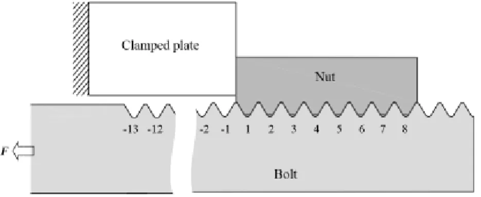
Fig. 1 shows the schematic diagram of bolt-nut connection. As shown in Fig. 1, in the experimental model, No.-13 is the starting thread, and in the analytical model, No.-3 bolt thread is the starting thread. In this paper, the thread number of Fig. 1 (b) will be used. Therefore, No.-3 thread used in this paper is the starting thread referring to No.-13 thread in the experimental specimen. Fig. 1 (c), (d) explains why the nut pitch should be larger. If the nut pitch is larger than the bolt pitch, at No. 1 thread left side surface contact before the loading is changed to no contact after the loading. However, if the nut pitch is smaller than the bolt pitch, the right side contact surface of No.1 thread before the loading is not changed and the contact force just becomes larger than the contact force of normal bolt-nut connection after the loading. Therefore, the largest stress concentration at No. 1 thread can be reduced only by the larger nut pitch.
(a) Experimental specimen (Considering Fig. 1 (b), No.-3 is used in this paper as the starting thread instead of No.-13)
(b) Analytical model (In this paper No.-3 is used as the starting thread referring to No.-13 in Fig. 1 (a))
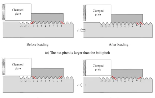
Before loading After loading (c) The nut pitch is larger than the bolt pitch
Before loading After loading (d) The nut pitch is smaller than the bolt pitch
Figure 1
Schematic illustration of bolt-nut connection
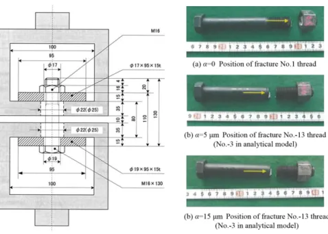
The 60 tonf Servo Fatigue Testing Machine with cycling frequency of 9 Hz is used in this experiment. The assembly drawing is illustrated in Fig. 2. In the first place, the fatigue experiment is performed for the specimen of α=15 μm, which is subjected to an axial force of F=30±14.1 kN. Since the cross sectional area of the bolt AR=141 mm2, the corresponding stress amplitude is 100 MPa. After repeated 1.94×10⁵ stress cycles, fracture does not happen. This experiment is conducted to investigate the fatigue life until the fracture with confirming the fracture position of the specimens under different pitch differences. To obtain the results in a short time, therefore, the fatigue load was changed to F=30±18.3 kN, for which the corresponding stress amplitude increased to 130 MPa. Under this loading, the fatigue experiment continues for another 2×10⁵ cycles, where the fracture happens. In the case of α=0 μm, under the load of F=30±18.3 kN the fracture happened at 2.19×10⁵ cycles, and for α=5μm, the fracture happens at 2.71×10⁵ cycles under the same loading conditions.
Fig. 3 shows the fracture positions of the three different specimens. For the standard bolt-nut connection (α=0 μm), the fracture happens at the first bolt thread. However, for α=5 μm and α=15 μm, fracture happens at thread No.-3 (see Fig. 3 and Fig. 1).
Figure 2 and Figure 3
Fatigue experiment device (dimensions in mm) – Fractured specimens
Utilizing a similar fatigue experimental result [17], the slope of S-N curves for α=0 μm, α=5 μm and α=15 μm are depicted in Fig. 4. Then, Miner’s rule is applied to calculate the equivalent fatigue life of α=15 μm under the load of F=30±18.3 kN, and the result is shown in Table 1. It can be seen that the fatigue lives of α=5 μm and α=15 μm are longer than that of α=0 μm. Among the three specimens, the specimen of α=5 μm has the longest fatigue life.
Figure 4 S-N curve
It should be noted that the stress concentration at No.-3 thread can be reduced easily to avoid the fracture by changing No.-3 thread shape because of no contact of the nut. Thus, for α=5 μm and α=15 μm, a longer fatigue life can be expected by controlling the fracture from No.-3 to No. 1-No. 8.
Table 1
Results of fatigue experiment
Specimens α=0μm α=5μm α=15μm
Axial force F (kN) 30±18.3
Stress σ (MPa) 213±130
Number of cycles until fracture
happen at No.1-8 threads 2.19×10⁵ >2.71×10⁵ >2.49×10⁵* Position of fracture No.1 thread No.-3 thread No.-3 thread
*:Until the number of cycles=1.94×10⁵ F=30±14.1 kN
3 Finite Element Method to Investigate the Stress Concentration
Fig. 5 shows the axisymmetric model of the bolt-nut connection created by using FEM code MSC.Marc/Mentat 2007. A cylindrical clamped plate is modeled with an inner diameter of 17.5 mm, outer diameter of 50 mm and thickness of 35 mm, whose inner diameter is nearly the same with the clamped body in the experimental device as shown in Fig. 2. The material of the clamped plate is SS41.
Here, the Young’s modulus is 206 GPa and the Poisson’s ratio is 0.3 for all the materials of bolt, nut and clamped plate. The bolt, nut and clamped body are modeled as three contact bodies. Friction coefficient of 0.3 with Coulomb friction is used for the analysis. The clamped body is fixed in the horizontal direction, and load F is applied on the bolt head as shown in Fig. 5. A fine mesh is created at the root of bolt thread with the size of 0.015 mm×0.01 mm, and 4-noded, axisymmetric solid, full integration element is used.
In the first place, in order to investigate the effect of friction, the stress concentration factor is calculated for α=0 μm by setting three different coefficient of friction, i.e. μ=0, 0.15 and 0.3, under an axial force of 30 kN. It is found that the friction effect is very small. In this study, therefore, the coefficient of friction is put equal to μ=0.3. As the first step, elastic analysis is performed.
Figure 5
Axi-symmetric finite element model
In Fig. 5, it should be noted that the stress concentration at No. 1 is the most important because the finial fracture happens at this thread. The stress concentration at No.-3 to No.-1 threads can be controlled and reduced by changing the thread shape because of no contact. For No. 7 or No. 8 threads, for example, the fracture at these threads does not mean the finial fracture because other threads may carry the load. Nishida [17] has discussed the fatigue strength of bolt-nut connection in detail. He has indicated that the fatigue limit of bolts is far lower than that of conventional notched specimens. Therefore, the notch factor Kf of bolts should be considered as Kf≈Kt although usually Kf <Kt. Here, Kt is the stress concentration factor of bolts. To improve the fatigue strength of bolt-nut, the stress concentration at No.1 thread will be focused in this study, because the finial fracture can be controlled to occur at this thread. Then, the effect of pitch difference on the stress concentration will be discussed.
3.1 Stress Concentration Factor
The stress concentration at the root of bolt thread is evaluated by using the stress concentration factor Kt defined by Eq. (1),
max t t
n
K
,
n
F
A
(1)where σtmax is the maximum tangential stress appearing at each bolt root, and σn is equal to the total bolt axial force F divided by the bolt cross section AR as shown in Fig. 6. It should be noted that the total force F is always used for all threads to compare the severity at each thread in Fig. 7.
Figure 6 Definition of Kt
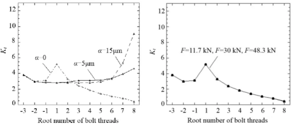
The Kt of each bolt root is indicated in Fig. 7 under the minimum load Fmin=30- 18.3=11.7 kN, mean load Fmean=30 kN and maximum load Fmax=30+18.3=48.3kN.
Fig. 7 (a) shows the comparison of the stress concentration factors Kt for α=0 μm, α=5 μm and α=15 μm under the same load of F=30 kN. It is found that when α=5μmis introduced, the stress concentration at root No. 1 reduces significantly.
However, the stress concentration at roots No. 7 and No. 8 increases largely when α=15 μm.
Fig. 7 (b) (c) (d) shows the stress concentration factors of each bolt root under different loads for α=0 μm, α=5 μm and α=15 μm. For the standard bolt-nut connection, with increasing the load, the stress concentration factor Kt at each root does not change. In the case of α=5 μm and α=15 μm, however, with increasing the load the stress concentration Kt at No. 8 decreases sharply.
It can be imagined that when the pitch difference is introduced the contact status between bolt threads and nut threads varies depending on the applied load. To make this point clear, the contact status of bolt and nut threads will be analyzed in the next section.
(a) α=0 μm, α=5 μm and α=15 μm under F=30 kN (b) α=0 μm
(c) α=5 μm (d) α=15 μm Figure 7
Stress concentration factor Kt at the root of bolt thread
3.2 Contact Status of Bolt-Nut Connection
The experimental load of F=30±18.3 kN is applied to the models of α=0 μm, α=5μm and α=15 μm. Before analyzing the stress state, the effect of pitch difference on the contact status of bolt and nut threads is investigated. Fig. 8 shows the total number of contact threads between bolt and nut with increasing the load from Fmin=11.7 kN to Fmax=48.3 kN. As shown in Fig. 8, for the standard bolt-nut connection (α=0 μm), all the nut threads are in contact with bolt threads independent of the magnitude of the load.
Figure 8
Total number of contact thread between bolt and nut for α=0 μm, α=5 μm and α=15 μm
However, for α=5 μm, only three bolt threads, i.e., No. 6, No. 7 and No. 8, are in contact with nut threads under F=Fmin, although with increasing the load the contact thread number increases. When F=Fmax, the contact status becomes similar to the case of the standard bolt-nut connection. For α=αmiddle under F=Fmin, only bolt threads No. 7 and No. 8 are in contact with nut threads, and even under F=Fmax, only three bolt threads No. 6 to No. 8 are in contact with nut threads.
3.3 Mean Stress and Stress Amplitude at the Root of Bolt Thread
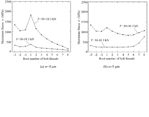
Fig. 9 shows the maximum stress, σ, at each root of bolt thread under different loads, i.e. Fmin=30-18.3 kN and Fmax=30+18.3 kN. The endurance limit diagrams for α=0 μm, α=5 μm and α=15 μm are obtained as shown in Fig. 10, based on the results of Fig. 9. Herein, the mean stress σm and stress amplitude σa are defined in Eq. (2),
max min
m
2
, max mina
2
(2)where σmax is the maximum stress of each thread under the maximum load F=30+18.3 kN, and σmin is the maximum stress of each thread under the minimum load F=30-18.3 kN. As shown in Fig. 10, the fatigue limit σw of the material SCM435 (JIS) is 420 MPa, and the yield stress σs is 800 MPa.
(a) α=0 μm (b) α=5 μm
(c) α=15 μm Figure 9
Maximum stress σ at the root of bolt thread under different loads of F=30-18.3 kN and F=30+18.3 kN
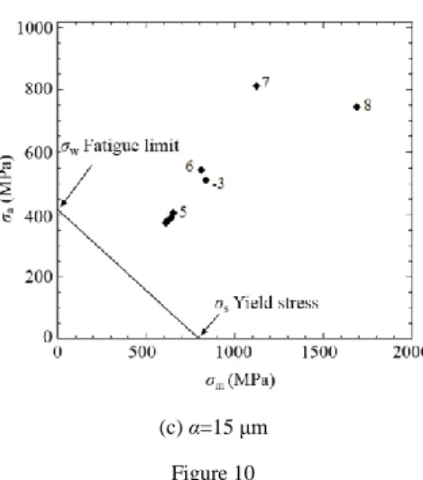
For the standard bolt-nut connection, the bolt thread No. 1 has the maximum stress amplitude as shown in Fig. 10 (a). On the other hand, for α=5 μm in Fig. 10 (b), it is seen that the stress amplitude, as well as, the mean stress at thread No. 1 decreases significantly. Compared with α=0 μm, the difference of each thread severity becomes smaller, which reflects the uneven load sharing among the bolt threads is improved. For α=15 μm in Fig. 10 (c), the large stresses appear at threads No. 7 and No. 8 instead of thread No. 1. From Fig. 10, it is also found that when the pitch difference is large enough, threads No. 7 and No. 8 become the most dangerous threads instead of thread No. 1 although the fracture at No. 7 and No. 8 does not mean the final bolt fracture because other threads may carry the load.
(a) α=0 μm (b) α=5 μm
(c) α=15 μm Figure 10
Endurance limit diagrams for α=0 μm, α=5 μm and α=15 μm
Since the results of elastic analysis show that the maximum stress is far beyond the yield stress of 800 MPa for the bolt material SCM435 (JIS), the elastic-plastic analysis is also performed for the models of α=0 μm and α=15 μm under the same load of F=30±18.3 kN. Here, the same material of SCM435 is considered for both bolt and nut. Fig. 11 indicates the equivalent stress at bolt threads where the high stress appears for α=0 μm and α=15 μm. For α=0 μm, the plastic strain zone only occurs at the root of the No. 1 bolt thread. On the other hand, for α=15 μm, the plastic strain appears at the root of No. 7 thread and the wide region of No. 8 thread. Fig. 11 shows that at No. 7 and No. 8 threads the fatigue cracks must initiate and propagate although those fractures do not mean the final bolt fracture because other No. 1-No. 6 threads can carry the load.
(a) α=0μm (b) α=15μm Figure 11
The equivalent stress in MPa under F=30+18.3 kN
Fig. 12 presents the endurance limit diagrams for α=0 μm and α=15 μm based on the elastic-plastic analysis considering the von-Mises stress at each bolt thread.
Similarly to the results of elastic analysis, the difference of each thread severity
For α=0 μm, the stress decreases significantly at No. 1 thread compared with the elastic analysis result. Similarly, for α=15 μm, the stresses at No. 7 and No. 8 threads decrease significantly.
For the experimental result shown in Fig. 3(c), the fatigue facture happens at No.- 3 thread (=No.-13 in the experiment) for α=15 μm. However, it is easy to reduce the stress concentration by changing No.-3 thread shape because of no contact of the nut. Once the fracture at No.-3 is avoided, for α=15 μm, the real fracture or at least the initial crack may occur nearby No. 7 and No. 8 threads because the large strains appear as shown in Fig. 11.
(a) α=0 μm (b) α=15 μm Figure 12
Endurance limit diagrams based on elastic-plastic analysis
4 Effect of the Bolt-Nut Clearance
As shown in Fig. 10 (a), (b) for α=0 μm and α=5 μm, the most dangerous No. 1 and No.-3 bolt threads in the FEM analysis agrees with the experimental results in Fig. 3. However, as shown in Fig. 10 (c) and Fig. 3 (c) for α=15 μm, the results of FEM and the results of the experiment do not coincide with each other. In other words, for α=15 μm, the fracture happens at No.-3 bolt thread while the most dangerous position appears at No. 7 and No. 8 threads in the FE analysis. In future research, the effect of the clearance between the bolt and nut on the stress state of the bolt threads will be investigated.
In the above analysis, the clearance between the bolt and nut is assumed as a standard value, i.e. 125 μm. The maximum clearance Cmax and the minimum clearance Cmin can be defined by Eq. (3) based on JIS:
max max min
1( )
2
nut bolt
C D d , min 1 min max
( )
2
nut bolt
C D d (3)
where Dmaxnut and Dminnut denote the maximum and minimum effective diameter of nut, respectively and dmaxbolt dminbolt denote the maximum and minimum effective diameter of bolt, respectively. From Eq. (3), for the M16 bolt-nut connection, the clearance ranges from 19 μm to 205 μm. However, the actual clearance can be determined by multiplying the maximum clearance by a factor ranged from 0.4 to 0.7. Thus, for M16 bolt-nut connections, the actual minimum and maximum clearance are Cmin=205 μm×0.4=82 μm and Cmax=205 μm×0.7=143.5 μm, respectively.
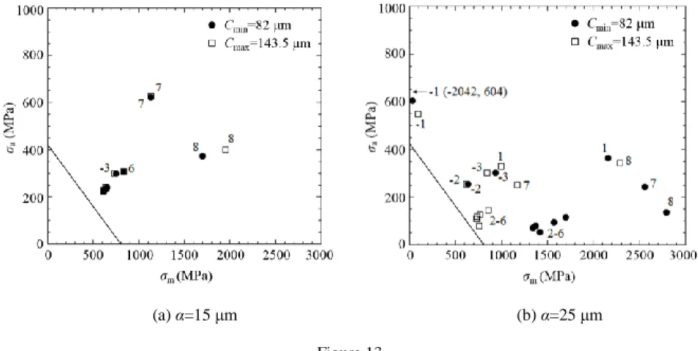
For α=15 μm and another larger pitch difference of α=25 μm, the elastic analysis is performed considering Cmin=82 μm and Cmax=143.5 μm. The load condition is F=30±11 kN. Fig. 13 shows the endurance limit diagrams for α=15 μm and α=25 μm considering the minimum and maximum clearances.
In Fig. 13 (a), when the clearance is changed from Cmin to Cmax for α=15 μm, the stress status at root No. 8 changes slightly. In Fig. 13 (b), for α=25 μm, with increasing the clearance from Cmin to Cmax, the mean stress decreases at roots No. 1 and No. 7 and the stress amplitude at root No. 8 increases slightly.
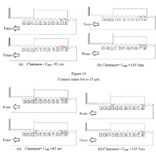
Fig. 14 and Fig. 15 show the contact status between bolt and nut for α=15 μm and α=25 μm considering the minimum and maximum clearance. The contacting threads are marked by the red arrows.
(a) α=15 μm (b) α=25 μm Figure 13
Endurance limit diagrams considering different clearance for α=15 μm and α=25 μm
Figure 14 Contact status for α=15 μm
Figure 15 Contact status for α=25 μm
For α=15 μm (Fig. 14), with increasing the clearance from Cmin to Cmax, the contact status between bolt and nut shows almost no difference under the same loads.
For α=25 μm (Fig. 15), it can be seen that the contact status is quite different, when the clearance changed from Cmin to Cmax especially under the load Fmax. From the comparison between α=15 μm and α=25 μm, it can be found that the clearance does not significantly affect the contact status for α=15 μm, but has a large affect for α=25 μm.
Conclusions
In this study, the fatigue fracture of bolt-nut connections having a slight pitch difference was considered, using experimental techniques and FEM analysis. The fatigue experiment was conducted for three specimens with different types of pitch differences. According to the FEM results, the stress states and the contact status at each root of bolt threads was presented and discussed. The conclusions can be summarized as follows:
(1) For the standard bolt-nut connection (α=0 μm), the fatigue fracture happens at No. 1 thread, while it happens at No.-3 thread in Fig. 1 (b) for α=5 μm and α=15 μm. The stress concentration at No.-3 thread can be reduced easily to avoid the fracture by changing No.-3 thread shape because of no contact of the nut. It is found that the fatigue life of bolt can be extended by introducing a suitable pitch difference, such as α=5 μm and α=15 μm.
(2) The FE analysis shows that both the stress amplitude and average stress at No. 1 bolt thread can be reduced by introducing a suitable pitch difference. For α=15 μm, instead of No. 1 thread, large stress appears at No. 7 and No. 8 threads although the fracture at No. 7 and No. 8 does not mean the finial bolt fracture.
(3) When the pitch difference is small, usually only No. 7 and No. 8 bolt threads contact with nut threads and the clearance changes. On the other hand, when the pitch difference is large, the contact status of No. 1 bolt thread may change from the left side contact in Fig. 1(b) to no contact. Therefore, with an increasing pitch difference, the clearance between bolt and nut significantly affects the contact status.
Acknowledgements
Mr. Ryuta Yosida and Mr. Huan Wang in the Mechanical Engineering Department, Kyushu Institute of Technology, are acknowledged for helping in the study. Partial financial support for this work from the Japanese Ministry of Education research expenses under grant no. 23560164 and Kitakyushu Foundation for the Advancement of Industry Science and Technology are appreciated.
The authors acknowledge the international collaboration grant funded by Commissie Wetenschappelijk Onderzoek (CWO), Faculty of Engineering and Architecture, Ghent University.
References
[1] Bichford, J. H.: An Introduction to the Design and Behavior of Bolted Joints, 3rd edition, Marcel, Dekker, New York, America, 1995
[2] Chaaban, A. and Jutras, M.: Static Analysis of Buttress Threads using the Finite Element Method. Journal of Pressure Vessel Technology, 114, (1992) pp. 209-212
[3] Chen, J. J. and Shin, Y. S.: A Study of the Helical Effect on the Thread Connection by Three Dimensional Finite Element Analysis. Nuclear Engineering and Design, 191 (1999) pp. 109-116
[4] Grosse, I. R. and Mitchell, L. D.: Non-Linear Axial Stiffness Characteristic of Axisymmetric Bolted Joint. ASME Transactions – Journal of Mechanical Design, 112 (1990) pp. 442-449
[5] Hard Lock Kogyo KK., Hard Lock Nut, Japanese Patent: 2002–195236, 2002 (In Japanese)
[6] Hirai, K. and Uno, N.: Fatigue Strength of Super High Strength Bolt.
Journal of Structural Engineering, 595 (2005) pp. 117-122
[7] Hobbs, J. W., Burguete, R. L., Heyes, P. F. and Patterson, E. A.: The Effect of Eccentric Loading on the Fatigue Performance of High-Tensile Bolts.
International Journal of Fatigue, 22 (2000) pp. 531-538
[8] Izumi, S., Yokoyama, T. and Teraoka, T.: Verification of Anti-Loosening Performance of Super Slit Nut by Finite Element Method. JSME – The Japan Society of Mechanical Engineers, 71 (2005) pp. 380-386 (In Japanese)
[9] Kawano, T., Kobayashi, Y., Harada, S. and Kuroshima, Y.: Fatigue Characteristics of Bolted Joints Tightened in Elastic and Plastic Region.
JSME – The Japan Society of Mechanical Engineers, 1 (2001) pp. 233-234 (In Japanese)
[10] Kenny, B. and Patterson, E. A.: Load and Stress Distribution in Screw Threads. Experimental Mechanics, 25 (1985) pp. 208-213
[11] Kenny, B. and Patterson, E. A.: The Distribution of Load and Stress in the Threads of Fasteners. Journal of Mechanical Behavior of Materials, 2 (1989) pp. 87-105
[12] Kuffova, M. and Necas, P.: Fracture Mechanics Prevention:
Comprehensive Approach-based Modeling? Acta Polytechnica Hungarica, 7 (5) (2010) pp. 5-17
[13] Majzoobi, G. H., Farrahi, G. H. and Habibi, N.: Experimental Evaluation of the Effect of Thread Pitch on Fatigue Life of Bolts. International Journal of Fatigue, 27 (2005) pp. 189-196
[14] Maruyama, K.: Stress Analysis of a Bolt-Nut Joint by the Finite Element Method and the Copper-Electroplating Method. JSME – The Japan Society of Mechanical Engineers, 19 (1976) pp. 360-368 (In Japanese)
[15] Nishida, S. I.: A Manufacturing Method of the Bolt Fastener, Japanese Patent: 2009-174564, 2009 (In Japanese)
[16] Nishida, S. I.: A New Method for Fatigue Life Improvement of Screws.
European Structural Integrity Society, 22 (1997) pp. 215-225
[17] Nishida, S. I.: Failure Analysis in Engineering Applications. Butterworth- Heinemann, Oxford, UK, 1994
[18] Nishida, S. I.: Screw Connection having Improved Fatigue Strength, United States Patent: 4.189.975, 1980
[19] Noda, N. A., Xiao, Y., Kuhara, M., Saito, K., Nagawa, M., Yumoto, A. and Ogasawara, A.: Optimum Design of Thin Walled Tube on the Mechanical
Performance of Super Lock Nut. Journal of Solid Mechanics and Materials Engineering, 2 (2008) pp. 780-791
[20] Noda, N. A., Xiao, Y. and Kuhara, M.: The Reduction of Stress Concentration by Tapering Threads. Journal of Solid Mechanics and Materials Engineering, 5 (2011) pp. 397-408
[21] Patterson, E. A. and Kenny, B.: A Modification to the Theory for the Load Distribution in Conventional Nuts and Bolts. Journal of Strain Analysis for Engineering Design, 21 (1986) pp. 17-23
[22] Suzuki, H. and Kunio, T.: Influence of Yield-controlled and Angle- controlled Tightening Methods on Fatigue Strength of Bolted Joints.
Journal of the Society of Material Science, 31 (1982) pp. 730-735 (In Japanese)
[23] Xiao, Y., Kuhara, M., Noda, N. A., Saito, K., Nagawa, M. and Yumoto, A.:
Optimum Dimensions of Thin Walled Tube on the Mechanical Performance of Super Stud Bolt. JSME – The Japan Society of Mechanical Engineers, 74 (2008) pp. 954-960 (In Japanese)
[24] Yakushev, A. I.: Effect of Manufacturing Technology and Basic Thread Parameters on the Strength of Thread Connections. Pergamon press, Oxford, UK, 1964
[25] Zhao, H.: Stress Concentration Factors within Bolt-Nut Connectors under Elasto-Plastic Deformation. International Journal of Fatigue, 20 (1998) pp.
651-659