A PRELIMINARY VEHICLE INSTALLATION STUDY FOR PROJECT SUNFLOWER
J.A. Rudy, D.W. Liechty, and J.E. Taylor
T H O M P S O N RAMO W O O L D R I D G E I N C .
New Devices Laboratories Cleveland, Ohio
Abstract
Parametric data and design considerations are presented to guide the evaluation of the applicability of Sunflower to specific mission, performance, and vehicle integration require
ments. This guide to specific tailoring of the system is limited in scope to those modifications involving no advance
ment in technology over that employed in the current develop
mental e f f o r t . The factors presented include:
a) Variation in solar collector size and heat storage capacity with specific cyclic illumination details b) Consideration of system packaging f l e x i b i l i t i e s c) Consideration of possible independent orientation
concepts
d) Power level variation considerations.
Examples are presented of systems tailored to typical Earth, Mars, Venus and lunar missions.
Introduction
Many potential applications exist for solar space power supply systems of a few kilowatts within the many c i v i l and military missions being studied today. Manned missions of even the relatively short duration of a few weeks typically require power of 1 - 1 / 2 to 2 kw or more. Unmanned applications involving the need to transmit information at the high rates associated with hemisphere voice or real time video coverage require similar power levels*
The Sunflower system development program has been i n i t i ated by the National aeronautic and Space administration with these general needs in view. The timing and technical approach of the Sunflower power system have been directed toward the effective use of the mercury Kankine space power system tech
nology which has been developed largely under the AEC-sponsored
S I X T H S Y M P O S I U M O N B A L L I S T I C M I S S I L E A N D A E R O S P A C E T E C H N O L O G Y
Snap programs over the last five years, US a result of this background development and of the specific objectives of the current Sunflower contract, Sunflower promises to be the f i r s t solar power system of greater than a few hundred watts a v a i l able to this country.
Thus, the Sunflower system is frequently considered for application to specific applications under study by industry and the government for the 196h and subsequent period.
This paper has been prepared to explore some of the flex
i b i l i t i e s which exist within the basic Sunflower concept and within its specific design limits. This presentation specifi
cally explores the possibilities of varying the system stowed configuration, deployment and extension techniques, and system power output. Some thoughts are also presented on means which may be employed to achieve independent orientation of the vehicle and power system.
It is hoped that these considerations w i l l aid in more accurately defining general areas of applicability of the Sun
flower system and in guiding specific application studies*
When potential of application is established i t is of course expected that detailed studies directed toward specific mis
sions and vehicles w i l l be required*
System Description
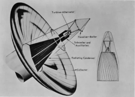
Sunflower is a solar-heated turboelectric power conver
sion system for space applications. The system concentrates and absorbs solar radiation and converts the resulting thermal energy to electrical power. The energy conversion is performed thermodynamically by a Rankine cycle which utilizes mercury as a working f l u i d . Heat is added to the cycle by the solar energy absorber and waste heat is rejected by direct radiation to the space environment. The major specification and opera
tional characteristics of the system are summarized in Table 1 . The collection and concentration of solar energy is per
formed by a déployable mirror which is an annular section of a paraboloid. The provision for launch packaging and subsequent deployment is effected by dividing the annular section into 30 segments with each hinged at the I . D . of the annular section which is also the base of the entire system assembly. Both the launch package and the deployed configuration are illustrated in Figure 1 . Each of the segments or "petals1 1 is a r i g i d alu
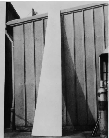
minum honeycomb structure with a vacuum raetalized reflecting surface. The solar collector concentrates the incident radia
tion through the aperture of a cavity absorber-heat storage b o i l e r component located at the focal point of the paraboloid.
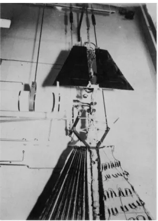
The area of the aperture is 1/600 that of the collector. A preprototype petal weighing 6- l / U pounds is shown in Figure 2*
40
Table 1 · Specifications and Characteristics of the Sunflower I Solar Dynamic Engine
Power Conversion System Specifications
Power Output Voltage Frequency
Mission Requirement
Power Package
Boiling temperature Boiling pressure Condensing temperature Condensing pressure Heat storage
Collector
Weight Summary
3 kilowatts
110 volts, line to neutral, two phase a.c.
2000 cps f 1%
Pated useful power continuously for durations up to one year. Circular earth orbits 300 to 20,000 nautical miles. Shade time 35 min up to 72 min, total orbital period 90 min up to 2U hours
Hermetically sealed Hg vapor turbine alternator pump unit
1050°F 2i|0 psia 600°F 6 psia
Heat of fusion of lithium hydride Outer diameter
Inner diameter Focal length Aperture angle
Cavity aperture Concentration ratio Solar collector
Boiler and heat storage Turbine alternator
Radiator condenser Mercury inventory Speed control Startup auxiliaries
Structure and miscellaneous
32.2 f t 9·6 f t 17 f t 53°
1.2 f t 600 156 lb 260 30
62 15 65 15
_67 700 lb or 233 lb/kw ilOOO nautical mile orbit - 560 l b , or 186 lb/kw
20,000 nautical mile orbit - 650 lb-, or 216 lb/kw
# Solar collector size based on minimum percentage sun time orbit (62-l/25b at 300 n.mi.)
Lithium hydride weight based on maximum shade time orbit (71 min at 20,000 n.mi.)
S I X T H S Y M P O S I U M O N B A L L I S T I C M I S S I L E A N D A E R O S P A C E T E C H N O L O G Y
Fig. 1. Sunflower I Power Conversion System.
4 2
Fig. 2. Preprototype Petal.
S I X T H S Y M P O S I U M O N B A L L I S T I C M I S S I L E A N D A E R O S P A C E T E C H N O L O G Y
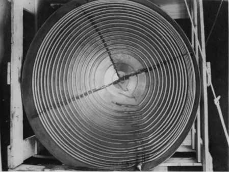
The radiant energy focused through the aperture is ab
sorbed by the surfaces of the cavity and concurrently stored as the heat of fusion of lithium hydride and conducted to the Rankine cycle b o i l e r . The energy stored in the lithium hydride is yielded to the b o i l e r during the dark period of the orbit to provide continuous operation.
The b o i l e r tubes are imbedded in the lithium hydride and contained between two concentric approximately hemispherical shells, h p a r t i a l l y assembled boiler cavity with the tubes in place is shown in Figure 3 ·
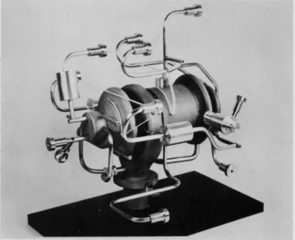
Mercury is pumped through the b o i l e r tubes and vaporized.
The thermal energy is extracted from the vapor and converted to electrical energy in a hermetically sealed turboalternator unit where a three stage impulse turbine, permanent magnet-alterna
tor and jet-centrifugal condensate pump are mounted on a single shaft and supported on liquid mercury lubricated journal and thrust bearings. This combined shaft unit (CSU) and several of its component parts are shown in Figure U»
The spent vapor exits from the turbine and is condensed in a finned tube radiator-condenser. The heat of vaporization is removed from the vapor and simultaneously radiated to space by fins that are brazed directly to the condensing tubes. Ad
ditional energy is extracted from the condensate and rejected by a secondary radiator. This subcooling prevents pump cavi
tation.
The Rankine cycle is completed by the jet centrifugal pump combination in the CSU which returns the condensate to the b o i l e r . A preprototype section of the Sunflower radiator-con
denser is shown in Figure 5 ·
The configuration of the Sunflower system presently under development was established as the optimum arrangement for the volume specified by NASA. Basically this volume is a cylinder 10 f t in diameter and 8 f t long, topped by a 15° half-angle conical section and located at the front of the vehicle. The arrangement is shown in Figure 6 and illustrates the detailed layout of the system and relative location of the various com
ponents. This configuration was specifically tailored to f i t the specified volume. The power system is r i g i d l y fixed to the payload volume which is a cylindrical section directly behind the power system. The entire vehicle-payload-power-system assembly is oriented toward the sun with an accuracy of 4 3 A of a degree, ÀS more complex missions are considered it~be- comes apparent that a variety of packaging arrangements and orientation requirements w i l l be required for the basic Sun
flower system. In considering these specialized requirements the task becomes one of packaging the basic Sunflower compo
nents in the volume available and then deploying the power system in such a way that concentrator orientation does not
44
Fig. 3. Partial Assembly - Preprototype Boiler.
S I X T H S Y M P O S I U M O N B A L L I S T I C M I S S I L E A N D A E R O S P A C E T E C H N O L O G Y
Fig. 4. Turbo-Alternator Mock-up.
46
Fig. 5. Preprototype Section of Radiator-Condenser.
Fig. 6. System Layout Drawing, Sunflower I, Side View.
SIXTH SYMPOSIUM ON BALLISTIC MISSILE AND AEROSPACE TECHNOLOGY
4δ
interfere with the prime mission objective. Several basic and relatively simple modifications that can be made to the Sun
flower system in order to t a i l o r i t to specific laissions are now described.
Design F l e x i b i l i t y
Previously published information. References 1 and 2 . have indicated the basic f l e x i b i l i t y of the Sunflower system to changes in mission requiring changes either to collector size or lithium hydride heat storage capacity* The solar collector size may be modified to reflect changes in the per
centage of v i s i b l e sun time and that the lithium hydride capa
city may be tailored to maximum expected shade period duration.
Litner of these changes may be accomplished with:
1. No change to the basic mercury Rankine power conversion system.
2. No addition of system temperature control complexity, since the basic design incorporates temperature
limit provision for off-design compatibility regard
ing cyclic power inputs.
The relations between collector size and lithium hydride capacity with mission visible sun conditions are included as Figures 7 and 8·
The following discussion covers additional features of f l e x i b i l i t y in design which are of interest in evaluating the adaptability of Sunflower to specific applications.
Stowage Arrangements
The Sunflower system pictured in Figure 1 is the result of a design study to meet a specific vehicle design envelope.
It is observed that this specific envelope is not universally suited to a l l payload vehicles, ϋη investigation of stowage innovations is therefore beneficial.
One possible objective is reduction of the axial length requirement of the stowed configuration. The current axial length was selected on the basis of an optimized focal length consistent with the highly desirable cavity-type receiver, the required collector diameter, and with considerations of "nor
mal" (intercepting) area versus collector surface area as a function of collector diameter to focal length ratio of approximately two. Thus, a 17-foot focal length was chosen for the 32.2-foot-diameter Sunflower collector. This focal length, together with the desire for a simple, fixed structure, determinedthe stowed length of the Sunflower package.
There are two simple ways to reduce this length:
1. Reduce collector diameter
S I X T H S Y M P O S I U M O N B A L L I S T I C M I S S I L E A N D A E R O S P A C E T E C H N O L O G Y
Fig. 7. Collector Diameter vs. Percentage Sun.
ί
50
130
0 1 0 2 0 3 0 4 0 5 0 6 0 7 0 8 0 M a x i m u m Shade T i m e , M i n
Pig. 8. Lithium Hydride vs. Maximum Shade Time.
S I X T H S Y M P O S I U M O N B A L L I S T I C M I S S I L E A N D A E R O S P A C E T E C H N O L O G Y
For applications permitting a greater percentage of visible sun time than the 62-1/2% currently estab
lishing the design, reduction in collector diameter allows reduction in focal length at constant D/f ratio. To illustrate, for a continuous sun mission, the collector diameter may be reduced to 25#3 ft and the focal length thus reduced from 17 ft to 12-1/2 ft.
2. Extendable collector support structure
The utilization of an extendable collector support structure can eliminate the coincidence of system packaged length and focal length. Such a system packaging modification can be accomplished by rear
rangement of component locations without the need to employ flexible or extending fluid carrying lines.
The basic changes are depicted in the sketch shown in Figure 9© -as shown, the basic modifications consist of relo
cating the major elements of the system out of the (deployed) optic path by moving them to the "sun side11 of the receiver.
Thus, extension of the collector support structure may be accomplished without effect on any elements of the system but the basic structure. Design studies have indicated the capa
bility of packaging the stowed system within the axial length required by the stowed collector. Thus, for a continuous sun mission, where solar collector petal length is 7·9 ft the stowed package length may be reduced by better than 60% from the current 21 f t .
The stowed package diameter of the Sunflower collector may also be reduced within certain limits. It is evident that as the deployed to stowed diameter ratio requirement increases, the applicability of the current rigid petal concept reaches a limit. Such limits are directly set by the number of petals employed to form the full paraboloid, AS the number of petals is increased, two criteria are adversely affected, cost and accessory hardware weight. However, since hinges, deployment drive and locking deployment restraints currently make up only 10% of the collector total weight, doubling the number of petals increases the weight by only 10%·
A correlation between number of petals and deployment diameter ratio is shown in Figure 1 0 . US shown, the use of 60 petals permits a do/d± of 6.3 · ixelative to the 25·3 ft diam
eter collector of a continuous sun mission, the stowed package diameter could be reduced from the current 9.5 ft to k ft.
A final aspect of system packaging is the frequent re
quirement for independent orientation of the vehicle and solar collector. This topic is difficult to subject to detailed scrutiny without a specific vehicle configuration defined,
^lso, it is found that the collector deployment approach and 52
^ 137" Collector Retracted^ ^ Fig. 9· Stowage Innovations of Sunflower Package. ^ 258" Collector Extended
S I X T H S Y M P O S I U M O N B A L L I S T I C M I S S I L E A N D A E R O S P A C E T E C H N O L O G Y
-ο- J
Fig. 10. Collector to Missile Diameter Ratio vs. Number of Petals.
54
considerations of system deployment as required to provide clearance for independent orientation are strongjy related from the standpoint of over-all packaging freedom and simpli
city.
Two concepts of independent collector-vehicle orientation have been conceived which appear to have some merit. The
first, shown on Figure 1 1 , has several apparent advantages*
As shown in the figure, the power system is attached to a single mounting ring as in the current Sunflower system.
Both the system support structure and the déployable rigid petal solar collector are mounted from this base ring.
In the proposed integration, however, this ring is not rigidly mounted to the satellite vehicle but is instead mount
ed to the end of orientation struts which extend down the sides of the mission module. The opposite ends of these mounting struts are hinged in a line normal to the vehicle longitudinal axis near the mid-point of the satellite to correspond with the station at which the mission and re-entry vehicles abut.- Thus it is apparent that rotation of this assembly about the hinge line will allow the power system to move in a full 360°
arc about the vehicle. Providing a ring gear and drive attachment between the vehicle itself and the orientation strut attachment axis, it is further apparent that a combina
tion of rotation about both of these axes pemits fully inde
pendent orientation of the solar power system and the satel
lite vehicle. Other features of this proposed system integra
tion include a provision for retractable supports between the power system and the mission module while the system is in the boost (aligned) position. This permits removal of boost acceleration loads from the orientation struts. In this man
ner the system in the boost configuration can be made as rigid as necessary without requiring massive orientation struts. At any time that corrective thrust is required during the mission, the power system may be returned to the boost (aligned) posi
tion and the retractable supports repositioned to support the power system. In this manner these struts may be designed for zero gravity conditions with their primary structural re
quirement being the ability to transmit the required angular accelerations to the power system. Once proper orientation is established, the power system in remaining pointed toward the sun will have an essentially fixed orientationj thus, even these torque loads may be established with considerable inde
pendence. The primary torque requirement would be established by the time allowed to return tne power system to the park position for mid-course guidance and for the subsequent repo
sitioning of the system to regain its orientation. The design provisions noted above combined with the possibility of employ
ing inflatable rigidizing plastic-filled beams for the orien-
S I X T H S Y M P O S I U M O N B A L L I S T I C M I S S I L E A N D A E R O S P A C E T E C H N O L O G Y
Fig. 1 1 . Yoke Deployment Concept.
5*
tation struts insure that the proposed concept may be accom
plished with only minimum compromises in increase of required vehicle skin diameter relative to vehicle diameter.
In summarizing the advantages which are achieved through the proposed system integration concept the following points are noted;
1· No extension or traversing is required in placing the power system in a position to be oriented, leather, the simple retraction of boost acceleration supports immediately frees the power system for full orientation freedom. Thus, system startup is accom
plished by the simple deployment of a solar collec- tor in no way more complex than that which would be employed in a vehicle of similar diameter if the poxrer system were rigidly fixed to the vehicle.
2. ut no time can the vehicle cast a shadow on the solar collector, therefore, no increase in solar collector size is required by the orientation re
quirement.
3. The system can straightforwardly be designed such that no disturbing torques are transmitted to the payload vehicle during solar orientation movements.
U. The system may be returned easily to the symmetrical position for mid-course thrust corrective action, thus affording the capability to return the vehicle center of gravity to coincide with the thrust vector.
The disadvantages of this approach include two factors:
1. Tae very fact of freedom from solar blockage by the vehicle causes the existence of possibly deleterious blockage of "view" from the vehicle. Thus, if sen
sors or transmitters are required to "see11 in a direction approximating the solar direction, prob
lems will arise.
2. The attractiveness of the yoke approach is compro
mised if vehicle length to diameter ratio reaches either excessively high or low values. Also, if the vehicle has protrusions in either diameter or length, the yoke must be sized to clear the maximum protru
sion.
These two disadvantages are partially satisfied by the concept shown in Figure 12, at some cost in support weight and packaging and deployinent simplicity. This is the straightfor
ward approach of extending the system sideways, deploying the collector, and providing the 360 degree freedom about the pitch and roll axes.
This system also enjoys freedom from vehicle shading of the collector.
S I X T H S Y M P O S I U M O N B A L L I S T I C M I S S I L E A N D A E R O S P A C E T E C H N O L O G Y
S u n f l o w e r Systems
Stowed C o n f i g u r a t i o n
Fig. 1 2 . Side Pod Mount.
58
Power Variation - Multiple Systems
The Sunflower system may be adapted to supply other than 3 kw of power. Relatively small changes may be accomplished by resizing the fluid carrying elements of the system to match working fluid flow and energy transfer to useful power output.
The primary elements affected would be boiler tube flow area, turbine admission, and radiator fin and flow areas.
Greater power generating flexibility can be obtained with virtually no redesign required by considering the use of multiple systems. Specific higher power designs may be
achieved in a number of alternate ways by integrating a multi
plicity of any of the major components of the system with larger counterparts of the remaining components. The specific configuration favored by TRW employs entirely separated work
ing fluid loops. Thus, separate boilers, turbogenerators, condensers, subcoolers and pump's and intercomponent lines are provided. This approach enjoys the redundancy advantages of permitting entirely independent operation of multiple systems with no requirement to sense failures and modify system plumb
ing routing to insure continued operation of the unaffected system in the event of failure of a component. The exceptions to redundancy which are felt to be attractive are the solar collector and optical cavity receiver. The utilization of a single collector and receiver, with parallel and separate boilers routed through the single receiver, may in some in
stances result in system packaging advantages in that a single large paraboloid may be found easier to stow and deploy in some vehicle configurations. In such a concept the failure of any single system within the complex would not deleteriously influ
ence the other systems. The primary result would be the imme
diate overpowering of the receiver by the collector, causing a rise in receiver cavity temperature. Since the optical system must incorporate temperature limiting protection to operate in the sun continuously anyway, the temperature rise will be con
trolled and the only effect will be earlier and stronger tem
perature limiting action.
Conversely, it may in some cases be desirable, however, to provide separate collector and receiver components as well as separate mercury Rankine elements. The result would be two or more entirely separate systems with separate deployment and, if desired, separate orientation provisions.
Thus, it is attractive to consider the use of multiple systems to obtain multiples of 3 kilowatts of power. In deriving the characteristics of such multiple systems, each separate system may be matched to the mission specifications as indicated in the preceding paragraphs, and the over-all char
acteristics approximated by combination of these elements. It
S I X T H S Y M P O S I U M O N B A L L I S T I C M I S S I L E A N D A E R O S P A C E T E C H N O L O G Y
is becoming increasingly clear that advanced solar dynamic power systems will be useful to at least £>0 kw, Reference 3·
Missions and Application Studies
The above discussion has briefly considered some of the elements which are germane to tailoring the Sunflower system to specific applications. While detailed consideration of vehicle integration applicability are best accomplished with benefit of specific mission and vehicle data, the following paragraphs are presented to illustrate the applicability of Sunflower to some specific missions of interest.
Earth Orbit
The earth orbit missions of Sunflower have been summa
rized in references 1 and 2 and will be only summarized here by presentation of Figure 1 3 , a presentation of system weight and collector diameter as required to operate at any specific orbital altitude between 300 nautical miles and 20,000 nauti
cal miles. For illustration, the 20,000 nautical mile system is selected for presentation on Figure liw At the collector diameter requirement of 26.2 f t , the two illustrations show basic package dimensions for a 60-petal, minimum-diameter package and for a 30-petal, 9.5-ft stowed diameter, minimum stowed length package.
Lunar Circumnavigation
A number of lunar missions fall within the range of possible application of a Sunflower type power system. Lunar circumnavigation missions may be typified today by several studies which have been conducted for manned lunar vehicles, and which may be generally separated into the following phases;
1. Earth launch
2. Earth parking orbit 3. Transfer orbit U. Lunar orbit 5. Return orbit
6. Re-entry and recovery.
The Sunflower system is well suited to meeting the power requirements of each of the above phases except initial earth launch and final re-entry and earth recovery. These two ex
ceptions result from the high aerodynamic loads encountered during initial and final phases. It is practical to provide auxiliary chemical power for the launch and recovery phases if this is required.
The sun-shade characteristics of lunar circular orbits
60
Fig. 13. System Weight and Collector Diameter at 300 to 20,000 Nautical Mile Operation.
S I X T H S Y M P O S I U M O N B A L L I S T I C M I S S I L E A N D A E R O S P A C E T E C H N O L O G Y
Radiator
9.5'
Fig. Ik. Sunflower Packaging Envelope Flexibility.
62
are summarized on F i g u r e 1 5 · Choosing an a l t i t u d e of UOO miles f o r i l l u s t r a t i o n , the shade time -maximum i s kS minutes, and the percentage sun time minimum i s 73%· À 3-kw system s i z e d f o r these l u n a r o r b i t i n g requirements may be s i z e d as f o l l o w s :
The s o l a r c o l l e c t o r s i z e may be d e r i v e d as f o l l o w s . The b o i l e r input power requirement i s 3ΐ±·3 kw.
D e t a i l e d design of the c a v i t y r e c e i v e r has i n d i c a t e d the average re r a d i â t ion power l o s s i s 6 kw over the c y c l i c c a v i t y s u r f a c e temperature range w i t h i n the c a v i t y of from 1150°F t o 1600°F. I n a d d i t i o n to these two power requirements an a v e r age energy l o s s through the i n s u l a t i o n surrounding the e n t i r e b o i l e r s u r f a c e may be expected t o occur a t the r a t e of 1*5 kw.
Thus, during the shade p e r i o d the l i t h i u m hydride w i l l be y i e l d i n g energy a t a r a t e of
3U + 6 f 1.5 = 1.1.5 kw
During the 62-minute shade p e r i o d the t o t a l energy g i v e n up by the l i t h i u m hydride w i l l e q u a l
i l l .5 x — - 1*2.9 kw-hr 60
Since t h i s energy must be c o l l e c t e d and s t o r e d i n the l i t h i u m hydride during the "sunlight1 1 p e r i o d of 158 minutes, the power increment r e q u i r e d w h i l e i n the sun f o r subsequent shade o p e r a t i o n equals
U2.9 kw-hr z
158/60 hr
T h e r e f o r e , the power r e q u i r e d to be absorbed by the c a v i t y while the system i s i n the sun i s
17.7 +1*1.5 = 59.2 kw
Experimental data accumulated to date under the Sunflower program has supported the a t t a i n a b i l i t y of a c o l l e c t o r e f f i ciency of 75% a t a c o l l e c t o r unit weight of 0·25 l b per f t2. This e f f i c i e n c y i s defined as t h a t p o r t i o n of the t o t a l energy i n t e r c e p t e d by the s o l a r c o l l e c t o r which i s d e l i v e r e d through an optimum s i z e a p e r t u r e i n the c a v i t y r e c e i v e r . The optimum c o l l e c t o r - c a v i t y r a t i o f o r such a c o l l e c t o r o p t i c a l q u a l i t y a t the c a v i t y temperature r e l e v a n t to the l i t h i u m hydride heat s t o r a g e component i s 600 t o 1 · Since the s o l a r c o l l e c t o r r e q u i r e d f o r t h i s example i s somewhat s m a l l e r than t h a t r e q u i r e d f o r the Sunflower m i s s i o n , an assumed e f f i c i e n c y of 75%
i s somewhat c o n s e r v a t i v e . Based on t h i s e f f i c i e n c y the r e q u i r e d s o l a r power i n t e r c e p t e d i s
•Ε- 1 000 2000 3000 4000 5000 Altitude - Miles Fig. 15. Lunar Orbital Characteristics.
SIXTH SYMPOSIUM ON BALLISTIC MISSILE AND AEROSPACE TECHNOLOGY
-Ô7Î5—
= 7 8'
9 k wAt a solar flux density of 129 watts/ft2 the required collector area is
7 8 - 9 ^ a . 610 f t2 0.129 kw/"
At the above noted weight of 0.25 l b / f t2 the resultant collec
tor weight is
610 χ 0.25 l b / f t2 = 152 lb
Assuming that a circular area five feet in diameter in the center of the collector is shaded by the boiler/heat storage component and associated structural numbers the collector outer diameter required for this area is found to be 28 feet.
It should be noted that as in the Sunflower system the collector efficiency assumed above is consistent with an assumed continuous orientated error of 0.75°· At tighter ori
entation control the collector efficiency may be increased and its size and weight decreased somewhat.
The weight of lithium hydride may be computed directly from the calculations performed above, which indicate that
^ 2· 9 kw-hr of energy must be yielded by the lithium hydride during the shade period. This energy comes from the heat of fusion of lithium hydride and from the change in sensible heat of the lithium hydride due to its temperature variation during the sun-shade cyclic conditions. An effective Δ Τ for sensible heat purposes of 200°F (consistent with variation in LiH aver
age temperatures from 1200°F to l400°F) is assumed. The speci
fic heat content of the lithium hydride is thus equal to
~ A Hfusion + C effective
= I 2 5 O Btu/lb + 1. 9 χ 200°F = I63O Btu/lb
The resultant weight requirement of lithium hydride is equal to 1+2.9 kw-hr χ 3^13 Btu/kw-hr _
1630 Btu/lb ~ ~ > J X D
With the solar collector and lithium hydride weight de
termined as noted above, the system weight may be synthesized as follows:
S I X T H S Y M P O S I U M O N B A L L I S T I C M I S S I L E A N D A E R O S P A C E T E C H N O L O G Y
Solar Collector
Boiler/Heat Storage Component Lithium Hydride
Turbogenerator Unit Condenser-Radiator Kotational Speed Control Startup auxiliaries Structure
Mercury Inventory
152 lb 155 lb 90 lb 30 lb 62 lb 15 lb
5 lb 59 lb 15 lb
Total 5Ô3 lb
For convenience of vehicle integration, an alternate design may be considered employing two systems. This will further serve the interest which has been expressed by poten
tial users in redundant systems. Such a design can be stowed in two diametrically opposite pods of minimum width require
ment, thus affording several.advantages in addition to the re
dundant system reliability, US shown on the sketch of Figure 1 2 , the pod design lends itself to stowage within axial loca
tions occupied by other elements of the vehicle in such a way that extension into an independent orientation configuration may be accomplished.
The system presented above, based on typical lunar orbit requirements, has considerable flexibility in meeting the other cited phases of a lunar mission without special provisions.
A possible additional requirement would arise, however, in providing for the capability of continued operation under the accelerations of transition to and from the transfer orbits involved. The Sunflower fluid system is hydrodynamically de
signed for operating insensitivity to accelerations. This in- sensitivity can encompass approximately 3 g's in a predicted direction with no change in design provisions. The structural problem imposed on the solar collector, however, must be solved.
The energy storage provision of the design clearly offers free
dom from the need for an operating solar collector during short acceleration periods. Two choices thus exist; design the solar collector with sufficient strength to prevent yielding while deployed under the transfer accelerations; or provide the capa
bility to restow the collector into its more rigid "bundlew configuration during transfer accelerations. The simplicity of the first approach has appeal. Sunflower collectors of the size required in the current example can be designed to with
stand 3 gfs while deployed at a negligible weight increase.
In considering missions to Mars an important fundamental variable is the reduction in solar intensity at the li|1.6 million mile distance of Mars from the sun. ut this distance
Mars Mission
66
the solar intensity is reduced to a value of approximately 56 watts per square foot, which is U2% of the value found at the earth's orbital distance. Thus, if the Sunflower system were to be employed on a Mars mission, the solar collector size would have to be increased. Figure 16 has been prepared to determine Mars heat storage and percentage suntime operating requirements. This figure presents a plot of percentage sun- time, orbital period and absolute shadetime as a function of orbital altitude for circular Mars orbit in the Mars orbital plane. Reference to Figure 16 permits an evaluation of system requirements over any selected range of Mars orbital altitudes.
A system capable of operation at any Mars altitude from 1000 to 10,000 miles would weigh 962 lb and require a solar collec
tor diameter of feet.
Since it should be possible to establish both an earth departure and Mars arrival orbit sufficiently skewed to the ecliptic plane to avoid planetary shadow operation altogether, the weight of a system compatible with continuous sun opera
tion for a Mars mission is of interest. A Sunflower system can perform a Mars mission without planetary shadow require
ments by removing the lithium hydride heat storage capacity from the system and by sizing the collector area consistent with the reduced solar intensity at the Mars orbit. The Sun
flower solar collector area of 7Ul square feet may be reduced by its 62-1/2% overdesign factor which was required at the low altitude ecliptic plane circular earth orbit and subsequently increased by the factor 1/U2 to allow for the solar intensity at the Mars orbit. This gives a requirement for collector area of 1090 square feet and a collector diameter of 37·2 feet, to yield a total system weight of 681 l b . It is emphasized that this system weight synthesis is based on exactly the same performance assumptions which are being employed in the design of the current Sunflower system*
Venus Mission
Figure 17 presents the variation in percentage suntime, absolute shadetime and orbital period with orbital altitude for circular Venus orbits in the ecliptic plane.
In considering Venus missions it is observed that even for adversely shaded Venus orbits, the percentage suntime is never a problem since the solar collector must be sized for operating in the lower solar intensity environment of the earth's orbit. At its distance of 67·2 million miles from the sun, the solar intensity at Venus may be expected to reach 21$
watts per square foot, an increase of 91%. Therefore, the solar collector may be ignored in defining orbital limitations about Venus and it may be observed that the Sunflower system
S I X T H S Y M P O S I U M O N B A L L I S T I C M I S S I L E A N D A E R O S P A C E T E C H N O L O G Y
Fig. 16. Mars Orbital Characteristics.
68
Fig. 17· Venus Orbital Characteristics.
S I X T H S Y M P O S I U M O N B A L L I S T I C M I S S I L E A N D A E R O S P A C E T E C H N O L O G Y
without modification will be capable of any orbit at altitudes below approximately 20.000 miles about Venus. Thus, the Sun
flower system need not be modified at all to accomplish the Venus mission and if earth departure orbits may be controlled
to exclude sunshade operation at departure, the resultant allowable reduction in collector size permits reduction of system weight to 630 lb while retaining 72-minute shade capa
bility at Venus. Such a 3-kw system would have a collector area of US6 square feet and a diameter of 25·9 feet.
Consistent with the assumption made in evaluating the Mars mission above, if sunshade operation can be avoided by sufficient departure from the ecliptic plane at arrival at Venus, the elimination of heat storage requirement allows re
duction in system weight to U50 lb.
Conclusions
Sunflower is applicable to a wide spectrum of missions both in terms of power level and system adaptation. The basic Sunflower concept is sufficiently flexible so that it may be packaged and utilized in several different configurations all of which use the components that are presently under develop
ment.
The wide applicability of Sunflower will cause it to emerge as one of a few standardized work-horse systems which will be used in sufficient numbers such that its inherent reli
ability goals are proved, Reference iw This benefit will be accompanied by a relatively low unit cost.
This paper has reviewed the factors which must be con
sidered when analyzing the use of Sunflower for a variety of mission categories. Even with the design flexibility inherent in the Sunflower system, it is apparent that the conventional approach to electrical power system integration must be modi
fied when considering Sunflower and other long duration, higher power systems. The effective utilization of these systems will require that they be given increased attention and that these operational requirements are fully considered early in the vehicle system design.
Finally, many applications are seen to be approaching within a time schedule such that Sunflower will be one of the few powerplants available in its performance class. For exam
ple, Dr. R. C. Seamans, Jr., associate administrator, NASA, testified recently that given sufficient budget, a man can be sent to the moon in six years, Reference 5 ·
70
References
1. Daye, C.J., "A Family of Solar Space Power Systems Based on the Sunflower Concept,w 61-AV-31* presented at the Aviation Conference at Los Angeles. March 12-16, l?6l.
2. Rudy, J.A.> "Tne Sunflower Power Conversion System,11 13U9-6, presented at the ARS Space Power Systems Confer
ence, Santa Monica, California, September 27-30, I960·
3· Ross, i).P. and J.E. Taylor, ttTurboelectric Power Genera
tion for Space Vehicles,11 350A, 1961 National Aeronautic Meeting, Society of Automotive Engineers, ρ 2.
h* Cooley, W.C., " A Comparison of Nuclear and Solar Power Systems for Manned Space Stations,11 Proceedings of the Manned Space Stations Symposium, Los Angeles, California,
IAS-NASA-RAND, April 20-22, I960, ρ 212.
5# Aviation Week, April 21., 1961, ρ 31·