Some Problems of Dynamic Contactless Charging of Electric Vehicles
Nikolay Dimitrov Mazharov
1, Stefan Milchev Hristov
1, Dimitar Andonov Dichev
2, Iliya Slavov Zhelezarov
21Faculty of Electrical Engineering and Electronics, Technical University of Gabrovo, Hadzhi Dimitar Str. 4, 5300 Gabrovo, Bulgaria
2Faculty of Mechanical and Precision Engineering, Technical University of Gabrovo, Hadzhi Dimitar Str. 4, 5300 Gabrovo, Bulgaria
E-mails: madjarov@tugab.bg, stefan.milchev@elkosys.com, dichevd@abv.bg, izhel@tugab.bg
Abstract: This paper presents a survey of the main publications and general design requirements and problems of inductive power transfer systems for dynamic charging of electric vehicles (EVs). The main different roadbed geometries, based on a single transmitter track and segmented transmitter coil array have been discussed. Different case studies considering charging scenario, vehicle speeds, power levels and transmitting and receiving coils geometry have been conducted. Some problems about the design of charging station and EV side control system and energy management system have been analysed. A prototype of a charging station has been developed and built to supply inductive power transfer system which delivers 10-35 kW power at an air gap between transmitting and receiving parts of 75-100 mm and horizontal misalignment of ± 200 mm.
The results have shown that the system can transfer the specified electrical power at efficiency of about 82-92% and that the inductive power transfer module and its dynamic matching during charging, exhibited high degree of stability under a misaligned (x-y-z) condition and battery state of charge.
Keywords: electric vehicle; contactless charging; transmitting and receiving coil; inductive power transfer; energy management system
1 Introduction
In the past decade, EVs have gained popularity due to concerns about environment pollution with greenhouse gases and a desire to move toward “greener” energy [1, 2, 4, 17]. The latest most popular plug-in technology for EVs has some disadvantages: the charging infrastructure (public charging stations) is vulnerable to weather conditions (rain, snow) and vandalism (stealing the cord, blocking the
outlet). The charging cable can represent a trip hazard, and due to the large amount of power being transferred, it also carries the risk of electrocution.
Contactless Charging (ClCh) technology for EVs improves upon EV convenience and related infrastructure as well as charging safety. EVs that are contactlessly charged are easy to use - the user simply parks or drives the EV into the charging area and allows it to charge. ClCh infrastructure can be built and sealed with no outlets, making it inherently safe from weather, vandalism, and electrocution hazards. One of the most important prerequisite for increasing the share of EVs, using ClCh technologies, is development of well-distributed infrastructure facilities which could allow more frequent charging and shorten the charging time required.
Concerning the contactless charging process (time, power, EV speed), several different techniques have been and currently are under investigation [2, 4, 7, 11, 12, 14, 15, 17]. The following categories could be identified, each having its benefits and disadvantages.
The first one is static charging, when the EV is stopped and parked [12]. Taking into account the duration of the charging time there are two possible solutions.
Long duration of static charging time, typically several hours, when the EV is stopped in a garage, parking lot, bus or taxi terminals, etc. The second solution is fast static charging time less than one hour [15].Typically, these charging spots are public. In both cases the charging process is based on some parameters that are specific to the battery of the EV and the capacity of the charging infrastructure.
The second category uses charging scenario when the EV is on-route. Also, two solutions are available. The first, when EV stops for a short period of time at the traffic light, bus stop, etc., is called stationary charging [9]. A stationary charging system could be very suitable in urban environments where the exact locations of EV stops could be predicted. The charging time is from seconds to minutes and high power is transferred from the infrastructure to the EV. The studies show [3-6, 8, 17, 18] that when implementing stationary charging the EV’s battery can have a considerably smaller volume. The second on-route charging solution uses scenario with movable EV [9, 11]. It is called dynamic charging. The idea is in public urban road infrastructure in some places, where there is speed limitations, for example before crossroads, traffic lights or eventually in highways to have a special road line and zone for charging of slow moving EVs. EV can be charged continuously while in motion and theoretically solve the EV battery problem with unlimited driving range. The vehicle may travel at constant or variable speed in a special lane that hosts the charging infrastructure. The advantage of dynamic charging is that this technology allows when EV passes over charging zone to add energy to batteries. As a result, the longer charging zone the lower battery’s capacity is needed, respectively its weight and more important cost. Also, the energy of charge depends on the speed - the higher speed, the less average energy is transmitted.
This paper endeavours to review the available dynamic ClCh technologies for EVs developed by charging technology companies, by car manufacturers, by universities and research institutes. The paper presents the authors’ results concerning analysis of power transfer in dynamic mode, overview architecture, primary and secondary side, communication problems on two levels and main features of energy management system. The developed dynamic inductive charging station (ChS) with power P=10-35 kW and frequency f=18-25 kHz is presented. The dynamic infrastructure containing four primary coils and different charging scenarios was tested at vertical air gap between transmitting and receiving coils - 75-100 mm and horizontal misalignment – up to ± 200 mm.
2 State of the Art Dynamic Charging
In dynamic charging infrastructure, vehicles are highly unlikely to be precisely aligned, so the currently agreed solution is the installation of visual signals would be put on the road to help the driver align the EV while driving. Charging a vehicle while it travels would mean that an EV user would not have to make stops to recharge during extended road trips. In fact, travels of hundreds of kilometres would be possible with dynamic charging to obtain portion or uninterrupted energy and to increase EV mileage. The analysis of the current situation in this area shows that the dynamic charging technology is still in R&D phase [4, 6, 7, 8, 9, 11, 14, 15, 23].
Dynamic EV charging approaches predominantly are based on inductive power transfer (IPT) technology and can be mainly categorized into two types based on transmitter array design - single transmitter track Fig. 1a) and separate segmented transmitter coil array Fig. 1b).
a) b) Figure 1
Dynamic ClCh scenarios: a) single charging pad; b) string of charging pads
The first type consists of a substantially long transmitter track connected to a ChS.
The receiver is noticeably smaller than the length of the track. The transmitter track can be from a few meters to several tens of meters long. There are some
drawbacks in this design - the electromagnetic field emitted within the uncoupled area must be suppressed to eliminate harmful exposure and the compensation capacitor should be distributed along the track to compensate large inductance and magnet coupling is fairly low because of the smaller transmitter area covered by the receiver coil resulting in lower efficiency.
Segmented coil array based designs have multiple coils connected to ChS.
Transmitter track based systems are easier to control as the track is powered by a single source. Magnet coupling along the track is nearly constant when the EV moves along the track. On the other hand, segmented coil array eliminates field exposure and requirement for distributed compensation as happen in single transmitter track.
Some of the notable achievements in designing dynamic EV charging platforms can be identified as follows. UC Berkeley has conducted a test as a proof-of concept of a dynamic ClCh system for EV based on IPT in the late 70s’ [10]. They transferred 60 kW of power through 7.6 cm distance to a passenger bus along 213 m long track. Due to limited semiconductor technologies, the operating frequency of Berkeley system was 400 Hz and only 60%efficiency.
KAIST On Line Electric Vehicle (OLEV) is the first on the market ready to support public transport by dynamic wireless high-power charging [11] - up to 180 kW for tramways and up to 100 kW for buses at 20 cm gap. The generated magnetic field around the EV is < 2.41 µT. The OLEV’s technology is presented in Fig. 2.
Figure 2
Wireless solutions for EVs in South Korea
Conductix-Wampfler, a German company [12], has developed a dynamic charging module that works on the principle of a construction kit - depending on the EV (car or bus), a charge of 60, 120 or 180 kW is delivered wirelessly. The charging modules are delivered ready for service, meaning that once the preparations have been made below ground, they only have to be lowered into the shaft. It takes very little time before the inductive charging point is ready to be used by the final users – Fig. 3.
The Conductix-Wampfler’s technology, in charging mode, the receiver coil on the bus is lowered to about 40 mm from the ground. This closeness to the charging plate allows the magnetic field to be focused in such a way that stray magnetic
fields remain almost entirely restricted to the immediate vicinity of the coil. Next to the vehicle, the field values are significantly below the thresholds prescribed by ICNIRP recommendations, i.e. generated magnetic field <<6.25 µT [12, 13].
a) b) Figure 3
Conductix-Wampfler ClCh technology: a) main components of ClCh station; b) installing a charging module at a bus station with 120 kW power
Bombardier’s PRIMOVE system addresses both the static and the dynamic charging needs of buses, cars, and even light rail systems [14]. Currently, Bombardier’s dynamic charging has only been applied to light rail systems, using single charging pads built into the track; however, it could be adapted for use with road vehicles. The system’s roadside components for buses include: transmitting coils which provide the inductive magnetic field; shielding to prevent electromagnetic interference; a Vehicle Detection and Segment Control (VDSC) cable that identifies PRIMOVE vehicles above the system; a Supervisory Control and Data Acquisition interface which supplies information for system control and diagnostics; and inverter and power supply cables. The on-board equipment includes a power receiver system of pickup cables and compensation capacitors, inverter, a battery, and a VDSC antenna. Bombardier’s PRIMOVE system is currently being used in public transportation by buses in Braunschweig, Germany.
There are some EU projects funded by FP7 program that investigated and developed contactless dynamic charging solutions [8, 9, 15]. The FastInCharge [8]
solution appears as being ambitious and innovative regarding the fact that it is applicable both to static and dynamic charging. The output power of the FastInCharge technology is around 35 kW (PMAX = 50 kW), which is one of the most powerful technologies that have been designed for mini busses. The air gap is from 75 mm to 100 mm. The system efficiency is close to 92% at zero misalignment between coils. The authors of this paper were responsible researchers and developers of IPT module and power electronics of two charging stations (fast static and dynamic) and both types of charging stations have been tested and validated in Douai, France [8].
However, dynamic charging introduces some other design challenges and problems. It is necessary to track the receiver coil position and switch the appropriate ChS, respectively coil, when the EV moves along the array. In addition, the distance between transmitting coils in horizontal direction needs to be carefully optimized. These coils cannot be kept too close to each other due to
two reasons. Firstly, negative mutual inductance between adjacent transmitter coils could generate negative current stress when several transmitting coils are supplied simultaneously. Secondly, design cost will be increased with many transmitting coils in a given length of the track. Connecting source converters to multiple coils is also a design issue. Several transmitter coils can be connected to a single power converter in parallel, or there can be one converter connected to each coil. In [8, 16, 18] a variant has been proposed in which several transmitting coils are powered by one ChS, consecutively by using electronic switches. On the other hand, the distance in vertical direction is also important. When the distance between transmitting and receiving coils is quite large, efficiency reduces quickly.
Additionally, a few more problems could be added in the implementation of dynamic EV charging systems such as strategies for dynamic IPT charging coil misalignment compensation, intelligent control on the transmitting charging side and receiving EV side levels, communication between these two levels and energy management of the whole dynamic charging process. Foreign-object detection and electromagnetic compatibility (EMC) issues are important safety requirements and have to be respected during development of every dynamic charging infrastructure [13]. Interoperability and standardization of dynamic contactless EV charging systems, including the proper terminology, are still opened issues, too.
3 Problems of Dynamic Charging
3.1 Analysis of Energy Transfer
The critical overview of the previous paragraph has shown, that for the purpose of the discussed dynamic infrastructure, the solution with separate segmented transmitter coil array was selected (Fig. 1b). The main advantage is that it is suitable for dynamic and also for static EV’s charging, what was an important requirement specified in FiC project [8]. Therefore, there are some geometrical and electrical parameters limitations of the transmitting and receiving coils. For example, the receiving coil is integrated in the EV and because of that positional and dimensional limitations are available. On the other hand, the geometrical and electrical parameters of transmitting coils must coincide with receiving coil in order to meet safety exposure requirements. The overall view of the developed dynamic infrastructure is shown in Fig. 4, where n numbers of transmitting coils are supplied by one ChS.
When two EVs sequentially move at a certain distance in a row in order to avoid the overlapping of two receiving coils from the group of transmitting coils the following condition has to be satisfied:
𝑥𝑛− 𝑥𝐸𝑉< 𝑥𝑑𝑖𝑠𝑡 , where (1)
𝑥𝑛− 𝑥1= (𝑛 − 1). (𝑥1+ 𝑥3+ 𝑥4) is the maximum distance between first and last coil supplied by one ChS; xEV is EV length; xdist is the distance between two EVs;
n is the number of coils connected to one ChS; xn is the distance from the beginning of the first coil to the end of the last coil, supplied from one ChS; x1 is coil length; x3+x4 is the distance between transmitting coils.
Figure 4
Dynamic infrastructure and energy transfer level
For determination of transmitted output power (POUT) was used the fundamental expression, given by [20].
𝑃𝑂𝑈𝑇 =2.[1+√1+(𝑘.𝑄)𝑃𝐿𝑂𝑆𝑆.(𝑘.𝑄)22] , (2) where Q is equivalent IPT quality factor and PLOSS are coils losses, which are divided between transmitting and receiving coils according to the ratio of both quality factors. We adopted (2) for the ratio of PLOSS toward the output power POUT
and it is equal to:
𝜆 =𝑃𝑃𝐿𝑂𝑆𝑆
𝑂𝑈𝑇 = 2. (1 + √1 + (𝑘𝑄)2) /(𝑘𝑄)2 , (3) It is obvious, that to achieve better efficiency it is necessary that λ<<1. Based on (3) there was made an analysis whose results are presented in Fig. 5 at k = 0.05- 0.5 and Q=10-50. The value of losses increases dramatically at 𝑘 < 0.1 and 𝑄 < 10. The implemented analysis proves that for the reliable operation of an IPT module it is necessary that 𝑘 > 0.3 and 𝑄 > 20, in other words 𝑘. 𝑄 = 6 ÷ 10.
Therefore, (3) could be simplified using above values:
𝜆 =𝑃𝑃𝐿𝑂𝑆𝑆
𝑂𝑈𝑇 ≈ 2. (1 + √𝛽𝐼𝑃𝑇2) /𝛽𝐼𝑃𝑇2≈𝛽2
𝐼𝑃𝑇 (4) where: 𝑘. 𝑄 = 𝛽𝐼𝑃𝑇 , 𝛽𝐼𝑃𝑇≫ 2.
If the magnet coupling k has low value (𝑘 < 0.3) it is possible by optimizing Q (increasing the inductance) to keep the ratio 𝑘. 𝑄 ≫ 6. Otherwise the IPT module will have bad cost efective indicators.
In low powered IPT systems (up to 500 W) is possible to transfer energy at bad magnetic coupling by optimizing the quality factor through correction of windings
inductance. A similar optimization process of Q for IPT electric vehicles chargers is economically unprofitable because of more litz wire and ferrites used and as a result more electrical losses. In some cases, it is appropriate to adjust the length and/or width of the coils.
Figure 5
Coil losses for different k and Q
By changing the size of the transmitting coil, at the same turns number, it can be assumed that there is almost proportional change of inductance and its active resistance and thus quality factor remains constant. Therefore, the transferred power according to (2) is changed proportionally in accordance with the magnet coupling, that in a given geometry of the transmitting and receiving coils depends only on their horizontal and vertical misalignment.
According to previous work done in [2-5] and our study [16-18, 19] it was proved, that the optimal relationship between the geometrical dimensions of the IPT coils are D/x1<0.25 (D is the vertical distance between the transmitting and receiving coils and x1 is the length of the coil), which guarantee magnetic coupling k greater than 0.3 (see Fig. 5) and hence, good energy transfer and efficiency. When D/x1 is close to 0.25, the efficiency of the wireless module is a maximum of 80%, while at D/x1<0.125, the efficiency reaches 93% [16]. Indirectly, these requirements are used in determination of the distance between the transmitting coils at dynamic charging.
The summary of the above results is shown in Fig. 6. It presents the dependence of efficiency as a function of horizontal misalignment between the coils (0, 100, 200 mm) and a vertical distance between them of 100 mm.
Figure 6
IPT efficiency Vs. output power and X&Y misalignment with 100 mm vertical air gap and power of 10-30 kW
The total max efficiency of the charging station from the mains to the battery at zero misalignment and 100 mm air gap is 90-92%. This efficiency is obtained by the charging station modules in the following way: (a) HF inverter - 97-98%; (b) IPT module 94-95%- primary 96-97% (copper app. 98%, ferrite core app. 98%), secondary 97-98% (copper app. 99%, ferrite core app. 98%); c) output rectifier - 98-99%.
In dynamic charging mode, movable car, misalignment x between transmitting and receiving coils has variable value and respectively magnetic coupling k. The dependence between these two parameters, for different transmitting coil dimensions has been investigated through computer simulations, using Ansoft Maxwell software tool (see Fig. 7). For all cases, the receiving coil dimensions are 800/700 mm and the gap between the coils is 100 mm, specified by concrete application [8].
Figure 7
Magnetic coupling k, at 100 mm air gap vs. horizontal misalignment and different transmitting coil dimensions
It is seen that for the same dimensions of transmitting and receiving coils (800/700 mm) and zero horizontal misalignment (x=0), k obtains the maximum value, equal to 0.51 (dark blue curve). The coupling is over 0.3 when x is in the range of -200 mm to +200 mm. The biggest area (-300 mm to +300 mm) of efficient energy transfer is at primary transmitting coil with dimensions 1200/700 mm, where the
maximum coupling is 0.37. Therefore, the maximum instantaneous power will be 0.37 / 0.51 times smaller compared to the dimensions 800/700 mm.
In accordance with Fig. 4 and (2), the average transferred power (that is proportional to k) from the transmitting to the receiving coils is determined by the expression:
𝑃 =𝑥 1
𝑂𝑁+𝑥𝑂𝐹𝐹. ∫0𝑥𝑂𝑁𝑃(𝑥)𝑑𝑥
, (5) where xON = 2.x4 is the distance when overlapping of two coils is less than permissible misalignment and k>0.3 and хOFF = x1 - x4 + x3 is the not transferred power distance (see Fig. 4).
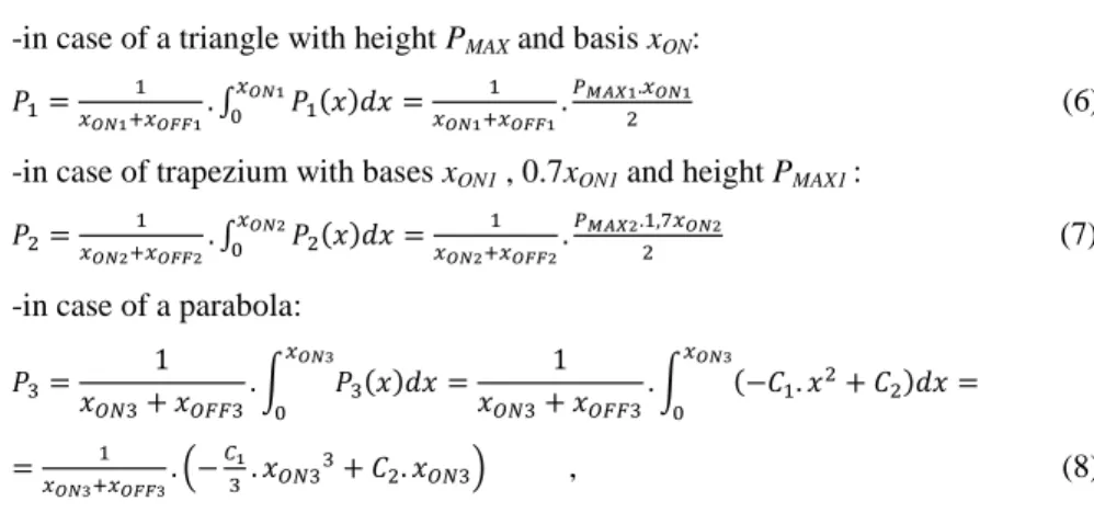
The determination of average power is carried out after approximation of P(x), with standard geometric shapes [21, 22]:
-in case of a triangle with height PMAX and basis xON: 𝑃1=𝑥 1
𝑂𝑁1+𝑥𝑂𝐹𝐹1. ∫0𝑥𝑂𝑁1𝑃1(𝑥)𝑑𝑥=𝑥 1
𝑂𝑁1+𝑥𝑂𝐹𝐹1.𝑃𝑀𝐴𝑋12.𝑥𝑂𝑁1 (6) -in case of trapezium with bases xON1 , 0.7xON1 and height PMAX1 :
𝑃2=𝑥 1
𝑂𝑁2+𝑥𝑂𝐹𝐹2. ∫0𝑥𝑂𝑁2𝑃2(𝑥)𝑑𝑥=𝑥 1
𝑂𝑁2+𝑥𝑂𝐹𝐹2.𝑃𝑀𝐴𝑋2.1,7𝑥2 𝑂𝑁2 (7) -in case of a parabola:
𝑃3= 1
𝑥𝑂𝑁3+ 𝑥𝑂𝐹𝐹3. ∫𝑥𝑂𝑁3𝑃3(𝑥)𝑑𝑥
0 = 1
𝑥𝑂𝑁3+ 𝑥𝑂𝐹𝐹3. ∫𝑥𝑂𝑁3(−𝐶1. 𝑥2+ 𝐶2)𝑑𝑥 =
0
=𝑥 1
𝑂𝑁3+𝑥𝑂𝐹𝐹3. (−𝐶31. 𝑥𝑂𝑁33+ 𝐶2. 𝑥𝑂𝑁3) , (8) where C1 a coefficient, characterized the slope and C2 tip parabola displacement.
The energy that is transmitted to the EV running over n number of transmitting coils at speed V is equal to
𝐸 = 𝑛. 𝑃. (𝑡𝑂𝑁+ 𝑡𝑂𝐹𝐹) = 𝑛. 𝑃. (𝑥𝑂𝑁+ 𝑥𝑂𝐹𝐹)/𝑉 , (9) where ton, toff is the time during which each transmitting coil is switched on / off. It is obvious that tON=V/xON , tOFF=V/tOFF.
Table 1 presents the results of average power value calculated by expressions (2)- (9) in accordance with the magnet coupling k - Fig. 7, the size of the transmitting coil and horizontal misalignment. The dimensions of the receiving coil (800/700 mm), the horizontal distance between each transmitting coils (800 mm) and the gap between the transmitting and receiving coils (100 mm) are unchanged.
From (9) and Table 1 it is obvious that the transferred energy value depends on the EV speed, number of transmitting coils and efficient power transfer distance – xON. Also, the results of this analysis could be used for calculating the maximum
EV speed in order to receive the necessary energy in a given dynamic infrastructure.
The length of the transmitting coil also determines the value of the transferred power. The highest instantaneous power is transferred at the same dimensions of the transmitting and receiving coils because the magnetic flux is closed symmetrically through their cores. When increasing the length of the transmitting coil to a certain value xON is increased, too. Instantaneous power value is smaller than the variant with the same coils dimensions and the average power increases up to maximum value. The next increase of the transmitting coil length decreases the area of efficient energy transfer and hence the average power value. The reason for this is that due to the considerable difference in dimensions of both coils the magnetic flux of the transmitting coil is closed in the area above it without reaching the receiving coil. This increases the leakage inductance and significantly reduces the magnet coupling. Additionally, it can be noted that this design has a significant area of the transmitting coil, which is not covered by the receiving coil and the electromagnetic field in this area will attack the nearest metal parts of EV or other equipment. As a result, actual electromagnetic standards are not satisfied [13].
Table 1
Transferred power value at different dynamic charging scenarios Receiving coil dimensions - 800/700 mm
Horizontal distance between each transmitting coils - 800 mm Vertical distance between the transmitting and receiving coils -100 mm Maximum power - 50 kW
Transmitting coil dimensions, mm
Horizontal misalignment in direction X (Fig. 4), mm
Maximum value of magnetic coupling
xON, mm
xOFF, mm
PMAX, kW
P, kW average power
Number of transmitting coils for the distance of 100 m
600/700 ±150 0.43 300 1100 42.2 4.4 71
800/700 ±200 0.51 400 1200 50 6.25 62
1000/700 ±250 0.46 500 1300 45.1 7.34 55
1200/700 ±300 0.36 600 1400 35.27 8.9 50
1400/700 ±250 0.38 500 1700 31.4 4.1 45
The last column of Table 1 presents the necessary number of transmitting coils which could be installed in the same length of dynamic charging zone – 100 m.
The transmitting coil - 1200/700 mm required about 20% less coils number compared with 800/700 mm variant, which respectively reduce the cost of switching sensors and other communication equipment. Complete economic evaluation and final decision can be performed considering the total production costs of transmitting coils, protective boxes and installation costs.
3.2 Control of Transmitting Power
In dynamic charging with movable EV and respectively its receiving coil, an important development issue is how to realise switching (on/off) of transferred energy. Three possible solutions have been analysed and investigated:
a) after “start charging” all transmitting coils to be supplied with low HF power.
When the receiving coil covers the proper transmitting coil, equivalent resistance decreases and the output HF generator current will increase. Monitoring these changes, the HF generator is switched on and specified value of energy is transferred. All other transmitting coils are still supplied by low HF power. This solution is not cost effective because each transmitting coil has to be supplied by separate HF generator;
b) monitoring of HF generator load when the receiving coil covers the proper transmitting coil. The equivalent impedance changes are used to start energy transfer only to this transmitting coil. There is a disadvantage – the impedance could be changed not only by receiving coil, but also by other metal parts from the car or other external metal parts;
c) using sensors for switching-on each transmitting coil, when requirements for correct re-covering with receiving coil are satisfied. Switching-off a transferred energy, is sensorless through measurement of the output HF generator current.
When it falls below specified value the generator is switched-off.
Through analysis the third solution has been selected and realised as a more reliable and cost-effective. It is visualized in Fig. 1b) and Fig. 4. It consists of n number of transmitting coils supplied from one ChS and sensors for starting the charge algorithm (points O, C, F, I in Fig. 4). The dynamic charging scenario of EV is possible, if two preliminary conditions are fulfilled. The first one includes some organizational issues, relating to the identification, payment, etc. The second one is technological - correct positioning of the receiving to the transmitting coil in the charging area. Correct positioning means that all specified requirements for misalignment between two coils are satisfied. It is preferable, if the used sensor could have possibility to register correct positioning and only after that to switch- on the proper transmitting coil. Additionally, the selected sensor must operate without influence by the high frequency electromagnetic field between the two coils. By means of experimental studies it was proved that the greatest functional reliability is achieved by a magnetic sensor - type MGT 201 [25], which consists of two parts - active and passive.
The active sensor part is mounted on the front wall of the transmitting coil in the direction of EV movement (direction X) - Fig. 4. The distance x4 between the sensor and this wall is subject of adjustment, and thus determine the moment of its activation, respectively starting of the charge, in accordance with the overlapping level of the transmitting and receiving coils, i.e. the maximum allowable misalignment in the EV movement direction.
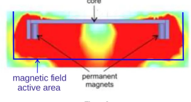
The sensor’s passive part, Fig. 8, includes two permanent magnets, magnetic core and a protective box and it is mounted to the rear wall of the receiving coil in the EV movement direction. The type of permanent magnets, geometrical dimensions and configuration of the magnetic core ensure accurate distribution of the magnetic field - Fig. 8, which is in accordance with specified correct conditions of horizontal and vertical misalignment between two coils. Only when these conditions have been implemented, magnet sensor switched-on and allows switching-on of the HF generator, in order to transfer electrical energy to the transmitting coil. As the displacement between the coils is larger, the output power is smaller. This means that when EV is moving and the receiving coil passes over the transmitting coil, the charging power at the beginning is minimum, it reaches a maximum at no misalignment and again goes to minimum value - Fig.
4.
Figure 8 Magnet sensor - passive part
The second minimum (Fig. 4 - points B, E, H, K) is used to stop the charge by the controller, located in the ChS and switch-off the transmitting coil, i.e. switching- off is sensorless. Thus, the ChS is ready to supply the next transmitting coil.
During the movement of EV, the same algorithm is repeated for each transmitting coil located in the charge area of dynamic charging infrastructure.
3.3 Dynamic Charging Architecture and Communication Levels
Fig. 9 presented overall-view architecture of developed dynamic charging technology for EV. It contains two main parts - ChS and EV side. All power electronic modules and relevant electrical circuits, for both sides, and EV battery pack are marked in grey. In ChS side, main electronic modules - AC/DC input rectifier and HF inverter and also in EV side- AC/DC module, are specially designed in order to fulfil specified electric parameters for dynamic charging as:
maximum transferred electrical energy, operating frequency, efficiency, etc. These parameters are also input data for the design of ClCh module.
magnetic field active area
To organise functionality of power electronic modules, the necessary control and communication units were developed and also are presented in Fig. 9. In EV side there are several units: vehicle management unit (VMU), which operates as a master, electronic control unit in EV side (ECU EVS) and battery management system (BMS) operates as slave controllers. They are connected through CAN bus.
ECU EVS controller receives data from AC/DC module: output DC current and voltage, AC/DC module temperature and from the mechanical unit (not shown in Fig. 9), positioning down and up the receiving coil. BMS is integrated in a battery pack and has monitoring functions regarding state of charge of EV battery.
In ChS two controllers are available: ECU ChS and charging station management unit (ChS MU). The first one compares data on measured output AC/DC current and voltage with set-up charging current and voltage and defines the proper HF inverter control signals. Information about ChS energy consumption is stored in ChS MU unit.
Figure 9
Contactless charging architecture – primary and secondary side
The communications of contactless dynamic charging EV technologies are organized and implemented on two levels. The low level is communication between ChS and EV charging units. It operates with technological and control data as: BMS defined set-up data (charging current and voltage), measured AC/DC output current and voltage, Start and Stop charging signals, etc. All data are transferred through Wi-Fi transmitter in EV side and Wi-Fi receiver in ChS.
This is one-directional communication. The higher level is between ChS and charging user (EV driver) with energy management system (EMS). It is organized and operates on regional level and serves a limited number of stations and users, respectively – Fig. 9.
Not only electrical, but also construction parameters are important. For example, electromagnetic field exposure, which must cover the relevant EMC standards, depends on IPT module shielding [13, 21]. Transmitting coils are part of road infrastructure, because they are built in the ground. Special construction measures are taken to guarantee reliable operation of transmitting coils - protection against external standard limited mechanical loads, against different environment conditions as: moisture, dust, extreme temperature, etc. To fulfil all these requirements, a special design of protective boxes for integration transmitting coils in a road was developed (Fig 10a)). Special attention was paid of the cover design and used materials - limited thickness of 40 mm, considering the specified gap between transmitting and receiving coils, max 100 mm, and to meet current standards for public roads [13], that means to withstand 12 tones external load.
The material selected was a polymer concrete reinforced with fiber glasses (non- metal is allowed) – Fig. 10b).
a) b) Figure 10
Dynamic charging architecture: a)protective concrete polymer box; b)real test of EV dynamic charging The discussed dynamic architecture has been realized, tested and validated at
power P=10-35 kW, frequency f=18-25 kHz, vertical air gap between transmitting and receiving coils -100 mm and horizontal misalignment - up to
±200 mm – Fig. 10 [8].
3.4 Energy Management
The electric power industry expects 400% growth in annual sales of EVs by 2023, which may substantially increase electricity usage and peak demand in high adoption areas. Understanding customer charging patterns can help utilities anticipate future infrastructure changes and to develop intelligence EV energy management system that will be needed to handle large vehicle charging loads, including contactless ChS [24]. Major findings could be grouped into two categories: charging behaviour and grid impacts.
Charging behaviours. The studies found [8] that the vast majority of in-home charging participants charged their vehicles overnight during off-peak periods.
Where offered, time-based rates were successful in encouraging greater off-peak charging. Public ChS usage was low, but primarily took place during business hours and thus increased the overlap with typical peak periods. EV owners frequently used the (often free) public stations for short charging sessions to “top off their tanks.”
Grid impacts. Length of charging sessions and the power required varied based on the vehicle model, charger type, and state of battery discharge. While the average power demand to charge most vehicles was 3-6 kW, the load from some electric vehicles that are using fast charging can be as much as 20 kW.
As the number of installed inductive chargers in the grid increases, the load profile of the network will be significantly modified, due to the high charging power served from this type of chargers. The additional charging demand may provoke grid issues such as voltage excursions, network overloading, etc. For that reason, an Energy Management System (EMS) is necessary in order to minimize potential disturbances in the normal operation of the grid. Additionally, the developed and used EMS must propose several services to EV drivers [8, 17, 24].
The energy management system fulfils the following objectives:
- monitoring the operation of the ChS - consumption in real-time in order to identify the demand flexibility that can be offered to support network operation;
- to enable the remote control of the maximum charging rate of the stations under emergency network operational conditions;
- user awareness of the location, the availability and the electricity cost of the contactless charging stations - the EMS makes EV drivers aware of the locations of the existing dynamic charging infrastructures in order to be able to decide the most convenient place for charging their EV in respect to their trip destination.
- to offer booking services to EV owners - enabling them to book the most suitable ChS at the most convenient time, considering their trip destination as well as the electricity energy prices.
The EMS architecture is presented in Fig. 9 and it comprises three components:
the user awareness module, the monitoring module and the decision module. At any time, EV owner needs to find info from the user awareness module about the exact location of the nearest available ChS. Based on this info EV drivers can reschedule their driving route to the desired destination in order to reach the most convenient and available charging scenario.
The monitoring module is responsible for the interaction between the ChS and the EMS and for remotely controlling the maximum allowable charging rate of all the charging stations in а given area. The actual charging rate is defined by the battery
management system of the EV which cannot be higher than the one defined by the EMS, respectively the current loading of the electrical network.
The decision module is responsible for purchasing energy from the wholesale market and supplies the charging demand of EV drivers. Finally, the decision module offers demand response services to the market operator. In case of network operational issues (voltage excursions or network equipment overloading), the decision module can support the problematic grid area by reducing the charging rate of the charging stations located at that area.
The presented EMS architecture, from charging application point of view, is usable for all EV charging technologies – plug-in, contactless, static and dynamic.
Its intelligence is based on the possibility to process the charging/booking requests from EV users as well as the demand response requests for network support in real-time. The EMS is responsible for the information management coming from the ChS, EV users and market operator and enables the interaction and information exchange between them.
Figure 9
The energy management system–main modules and communications Conclusions
This paper outlines some technical problems and results concerning design and implementation of dynamic EVs charging. The necessary power electronics and control units, that guarantee correct charging process, are described in the
presented architecture of dynamic ChS. The concept of two hierarchical communication levels between ChS, EV charging components and EM has been defined and the main features of used units have been discussed. The new research results considered are:
- defining the magnet coupling dependences as a function of misalignment and transmitting and receiving coils dimensions;
- dependence of power transfer efficiency Vs. magnet coupling, IPT quality factor and misalignment;
- reliable solution for control of transferred energy, and admissible misalignment, using magnet sensor and proper construction of its passive part;
- original construction of protective box of transmitting coils, built in a road, using polymer concrete reinforced with fibre glass, enabling to minimise the thickness of the cover.
All achieved results have been taken into account during design and practical implementation of dynamic road infrastructure. They are validated through dynamic inductive EV charging system with power of 35 kW (P MAX = 50 kW) and efficiency of transferred energy (grid to EV) close to 90-92% at a distance between transmitting and receiving coil of 100 mm.
The proposed theoretical analysis, design considerations and practical work were done in the frame of EU FP7 project FastInCharge [8].
References
[1] Jin H. and Rim C. T., "KAIST wireless electric vehicles - OLEV," SAE International, Vol. 1, pp. 1-10, 2011
[2] Wu H. H., Gilchrist A., Sealy K., Israelsen P. and Muhs J., "A review on inductive charging for electric vehicles," in Electric Machines & Drives Conference (IEMDC), 2011 IEEE International, 2011, pp. 143-147
[3] Miller J. M., Scudiere M. B., McKeever J. W., and White C., "Wireless power transfer," in Oak Ridge National Laboratory's Power Electronics Symposium, 2011
[4] Covic G., Boys J. T., "Modern Trends in Inductive Power Transfer for Transportation Applications", IEEE Selected Topics in Power Electronics, Vol. 1, No. 1, March 2013
[5] Garnier L., Chatroux D., '' Understanding the unbalancing of a battery pack to choose the best balancing solution'', PCIM 13, 14-16 May 2013, Nurnberg, Germany, ISBN 978-3-8007-3505-1
[6] Chopra S., Bauer P.,"Analysis and design considerations for a contactless power transfer system", Telecommunications Energy Conference (INTELEC), 2011 IEEE, Oct. 2011
[7] Kamath H., "Program on Technology Innovation: Impact of Wireless Power Transfer Technology", Electric Power Research Institute (EPRI), California, 2009
[8] “Innovative fast inductive charging solution for electric vehicle”, part of 7th Framework Program of EU, www.fastincharge.eu
[9] “On-road charging of electric vehicles”- The fabric project, part of 7th Framework Program of EU, http://www.fabric-project.eu/
[10] Covic G., Boys John T., Budhia M., Huang C., "Electric Vehicles – Personal transportation for the future", World Electric Vehicle Journal Vol.
4, Shenzhen, China, Nov 5-9, 2010
[11] OLEV Technologies /On Line Electric Vehicles/, http://olevtech.com [12] Conductix Wampfler, www.ipt-technology.com
[13] ICNIRP – International Commission on Non – Ionizing Radiation Protection, EMF Guidelines 1998, 1999, 2001, 2008, 2009, 2010, 2014, www.icnirp.org/en/publication
[14] Bombardier, http://primove.bombardier.com [15] UNPLUGGED project, http://unplugged-project.eu/
[16] Madzharov N., Tonchev A., ''IPT Station for static and dynamic charging of Electric Vehicles'', International Scientific Conference PCIM 2014, Nuremberg, Germany
[17] Madzharov N., Tonchev A., ''Inductive high power transfer technologies for Electric Vehicles'', Journal of Electrical Engineering, Vol. 65, No. 2, 2014, 125-128, ISSN 1335-3632
[18] Madzharov N. D., Ilarionov R., Tonchev A., ''Systems for dynamic Inductive Power Transfer'', Indian Journal of Applies Research, Vol.: 4, Issue: 7, July 2014, ISSN-2249-555X, IF: 2.1652
[19] Donati A., N. Madzharov, A. Melandri, F. Sighinolfi Induction sealing device for producing portable food packages –, US patent - US 8,286,406,B 2 - Otc 16, 2012
[20] Li S., Mi C., Wireless Power Transfer for Electric Vehicle Applications IEEE journal of emerging and selected topics in power electronicS, Vol. 3, No. 1, March 2015, pp. 4-17
[21] Dichev D., Koev H., Bakalova T., Louda P. А Меаsuring Method for Gyro- Free Determination of the Parameters of Moving Objects. Metrology and Measurement Systems, 23 (1), 2016, 107-118, ISSN 0860-8229
[22] Kraev G., N. Hinov, D. Arnaudov, N. Ranguelov and N. Gradinarov,
„Multiphase DC-DC Converter with Improved Characteristics for Charging Super capacitors and Capacitors with Large Capacitance”, Annual Journal of Electronics, V6,B1,TU of Sofia, Faculty of EET, ISSN 1314-0078, pp.
128-131, 2012
[23] Bankov N., Vuchev Al., Terziyski G., Operating modes of a series-parallel resonant DC/DC converter. – Annual Journal of Electronics, Sofia, 2009, Volume 3, Number 2, ISSN 1313-1842, pp. 129-132
[24] Karfopoulos E., Hatzoplaki E., Safalidis G., Karakitsios I., Kamarinopoulos A. and Hatziargyriou N., Energy Management System for fast inductive charging network: The FastInCharge project, MedPower Conference 2014, IET, 2014, Athens, Greece
[25] http://www.ifm.com