DOI: 10.1556/606.2020.15.2.10 Vol. 15, No. 2, pp. 106–117 (2020) www.akademiai.com
SEISMIC RETROFIT OF STEEL FRAME STRUCTURES
Magdy ISMAIL*
Faculty of Engineering and Information Technology, University of Pécs, Boszorkány u. 2 H-7624 Pécs, Hungary, e-mail: magdyibrahim@m-eng.helwan.edu.eg
Received 1 November 2019; accepted 30 Dcember 2019
Abstract: Moment resisting frames are considered as an effective seismic force resisting system that is used for steel structures. Some of these structures that were built in high seismic hazard zones were designed according to old strength-based design codes. Currently, these structures do not meet the requirements of the new seismic codes. Therefore, the seismic retrofit of these structures is mandatory and cannot be overlooked. Steel braces and concrete-steel composite elements are common solutions for enhancing the seismic behavior of existing steel frame structures. This paper presents a numerical study that evaluates different possible techniques for the seismic retrofit of existing steel moment-resisting frame structures. The study investigates the performance of three multi-story buildings with different heights that are located in a high seismic hazard zone. Three retrofit techniques were introduced including; 1) X-Steel braces, 2) buckling restrained composite braces, and 3) composite concrete-steel plate shear walls.
The seismic performance enhancement of the studied structures was evaluated in terms of the structure’s fundamental period, maximum inter-story drift and maximum base shear-to-weight ratios. Moreover, the cost of retrofitting material was estimated for each technique and they were compared to select the retrofit technique with the least constitutive material cost.
Keywords: Steel structures, Moment resisting frames, Seismic retrofit, Dynamic analysis, Material cost
* Corresponding Author
1. Introduction
Steel moment-resisting frame structures located in high seismic hazard zones are susceptible to excessive lateral deformations during strong ground motions. Some of these structures were designed according to strength-based codes, and hence they are in an urgent need for seismic retrofit. The retrofit should aim to limit the structure’s inter- story drifts by increasing the structure’s lateral stiffness in order to mitigate potential problems due to geometric nonlinearity and/or failure of beam-column connections [1].
In addition, excessive damage of non-structural elements should be avoided. The objective of this study is to investigate the seismic performance of three multi-story steel frame buildings with different heights that are located in a high seismic hazard zone. Three retrofit schemes were introduced including; 1) X-Steel bracings;
2) buckling restrained composite bracings; and 3) composite concrete-steel plate shear walls
.
The seismic performance enhancement of the studied structures was evaluated in terms of the structure’s fundamental period, maximum inter-story drift ratio and maximum base shear-to-weight ratio. In addition, the cost of retrofit material was estimated for each technique and they were compared to select the retrofit technique with the least constitutive materials for each height considered.2. Description of the selected buildings
Three existing steel buildings with different heights were considered in this study.
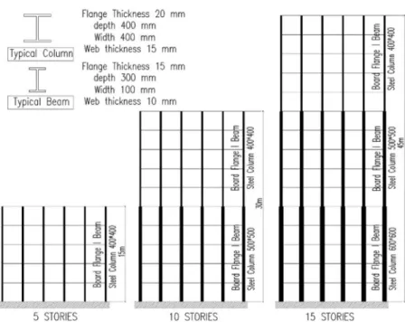
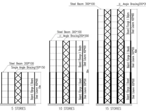
The buildings were designed according to a pre-1970 design code (ACI 1968) [2]. The buildings are of heights five, ten, and fifteen stories that represent low- and medium-rise buildings. The three buildings have the same floor plan that consists of five symmetrical bays in each direction of 4 m length. The Reinforced Concrete (RC) floor was designed to carry its self-weight and a live load of 2.0 kPa and a superimposed dead load of 2.0 kPa. The floor height is 3.0 m, the slab thickness is 140 mm and the total height of the three buildings are 15, 30 and 45 m. Fig. 1 shows the elevation of the three selected buildings as well as the beam and column sections. The column dimensions varied along the height according to the change of the axial load acting on each group of columns, while the beam dimensions were assumed to remain the same for the entire building. For existing buildings, the compressive strength of concrete was assumed to be fc' = 25 MPa and the yield strength of steel was taken as fy = 400 MPa. The modulus of elasticity for existing concrete was 22 GPa and for steel material was taken 200 GPa.
The concrete density was assumed to be 24 kN/m3, and Poisson’s ratio was taken 0.2 for concrete and 0.3 for steel material. The compressive strength of the new concrete used for retrofit is taken fc' = 40 MPa and its modulus of elasticity is 30 GPa. The existing buildings were assumed to be located in San Francisco, California, which represents a high seismic hazard zone in the United States. In this study, the existing buildings were strengthened so that the maximum inter-story drift value does not exceed 1.20%. This limit was set to maintain the non-structural elements and not to affect the gravity load resisting system.
Fig. 1. Elevations of the studied 5-, 10-, and 15-story frame buildings
3. Different retrofit schemes
In the present study, three different techniques were considered for the seismic strengthening of existing steel frame buildings located in a high seismic hazard zone.
The aim of building strengthening is to increase the building lateral stiffness and hence reduce the building deformations under design loads. The retrofit techniques are namely;
3.1. Retrofit using steel angle braces
Braced steel frame systems are considered by designers as an efficient and economical lateral load resisting system. However, their performance during severe ground motions was not satisfactory due to buckling of bracing members under compression, which resulted in a major loss of the frame strength and stiffness [3]. In the present study, existing frame buildings were strengthened by introducing steel X- braces in the middle external bays of the 5- and 10-story buildings, and two bays were braced for the 15-story building as it is shown in Fig. 2. The braces were installed along the full height of the frame. The brace section selected for strengthening the 5-story frames is a single equal angle (200 x 200 x 30 mm), and two back-to-back equal angles (200 x 200 x 30 mm) for the 10- and 15-story frames. The cross-sectional areas of the brace sections are 111, 222, and 222 cm2 for the 5-, 10-, and 15-story buildings, respectively.
Fig. 2. Seismic retrofit of the studied buildings using steel X-braces
3.2. Retrofit using buckling restrained braces
Buckling Restrained Brace (BRB) is a composite element that is usually composed of a ductile metal core (usually steel) that is enclosed by a continuous concrete-filled steel tube. Several research studies showed the effectiveness of BRB in the seismic resistance of steel frames [4]-[7]. The main advantage of the BRB elements over the conventional concentric steel braces is preventing the lateral and local buckling behavior using the concrete core. Meanwhile, the steel core is responsible for the tensile strength and ductility of the element.
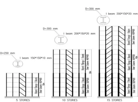
In the present paper, the steel frame buildings were retrofitted by introducing buckling restrained braces as it is shown in Fig. 3. Similar to the steel angle braces, the existing frames were strengthened using the BRB in the middle external bays of the 5- and 10-story frame buildings, while two bays were braced for the 15-story building. The BRB cross-section used is a composite circular concrete-steel I-section encased with a 3 mm steel tube. For the 5-story building, the radius of the circular BRB was 250 mm and the steel I-section was 150 x 150 x 10 mm. For the 10-story building, the radius of the circular BRB was 300 mm and the steel I-section was 200 x 150 x 20 mm. For the 15-story building, the BRB radius was 300 mm and the steel I-section was 200 x 200 x 20 mm.
Fig. 3. Seismic retrofit of the studied buildings using BRB braces
3.3. Retrofit using composite plate shear walls
Composite plate shear walls are considered to be a relatively new seismic force resisting system used for steel buildings. They can be utilized by either laying a concrete layer connected to two steel plates using shear studs, or by bonding the concrete layer with Fiber-Reinforced Polymer (FRP) sheets/plates. Several experimental and numerical studies investigated the behavior of composite concrete-steel plate shear walls under earthquake loading [8]-[10].
In the current study, the existing buildings were strengthened by introducing a composite concrete-steel plate shear wall in the middle external bays of the 5- and 10-story buildings. The wall composed of a concrete layer that is sandwiched between two layers of 3 mm steel plates. The thickness of the concrete layer is 10 and 15 cm for the 5- and 10-story buildings, respectively. For the 15-story building, two composite walls were used for each external frame with two layers of 3 mm steel plates and a 15 mm of concrete in between as it is shown in Fig. 4.
4. Linear dynamic analysis of the selected buildings
Linear dynamic analyses were conducted for the 5-, 10-, 15-story frame buildings with different retrofit schemes. Three dimensional linear dynamic analyses were conducted using the computer software ETABS, it is a program based on finite element analysis [11]. The P-∆ effect was considered in the numerical analysis. The building floors were assumed to act rigidly in the horizontal directions (two dimensional rigid
diaphragms). The frame foundations were modeled as fixed supports. The number of mode shapes considered in the analysis was taken as 12, representing the first four mode shapes in the three directions (Ux, Uy and Rz). The sum of Modal Participating Mass Ratios (MPMR) in each direction considering the first four mode shapes were found to be at least 0.93 of the total building mass, which exceeds the minimum required ratio of 0.90 according to the design code.
Fig. 4. Seismic retrofit of the studied buildings using composite plate shear walls The existing and retrofitted buildings were analyzed using the design response spectrum of San Francisco city according to the ASCE 7-10 [12]. The retrofitted buildings were designed to satisfy the requirements of ACI 2008 [13] and AISC 360-10 [14]. The nonlinear forces and deformations were obtained by using the response modification factor R (for the seismic forces), and the deflection amplification factor Cd. The values of R and Cd for existing and retrofitted structures are presented in Table I.
Table I
Response modification factor (R) and deflection amplification factor (Cd) [12]
Retrofit system
Dual systems with special moment frames capable
of resisting at least 25% of prescribed seismic force Existing structures
X-steel braces BRB Composite
plate wall Response modification
factor (R) 7.0 8.0 7.5 3.5
Deflection amplification factor (Cd)
5.5 5.0 6.0 3.0
5. Analysis results
5.1. Dynamic properties of the selected buildings
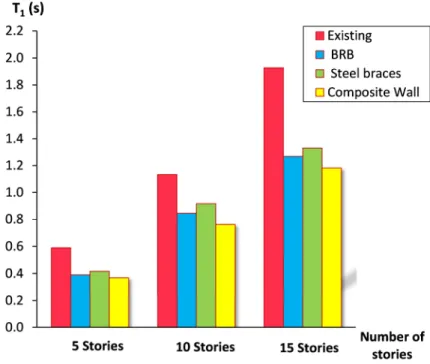
Modal analyses were conducted for the 5-, 10-, and 15-story frame buildings for existing and retrofitted structures considering a 5% damping ratio. Fig. 5 shows the fundamental period of existing and retrofitted buildings with different heights. From the figure, it can be seen that the retrofit schemes decreased the structures’ fundamental periods due to the additional stiffness provided by the retrofit system. It can be also noticed that the fundamental periods of the retrofitted buildings were similar to each other for the same building height. This is due to the inter-story drift limit of 1.20% that was set for all retrofitted buildings to determine the required stiffness of the retrofit system. Therefore, the retrofitted structures had similar stiffness’s and fundamental periods for the same building height. The modeling of the interactions between the component parts of the connection, in particular, the interaction between the welded surfaces has been modeled by a tie constraint, so that no relative motion between the surfaces in contact is possible [15].
Fig. 5. Fundamental periods of the 5-, 10-, and 15- story buildings
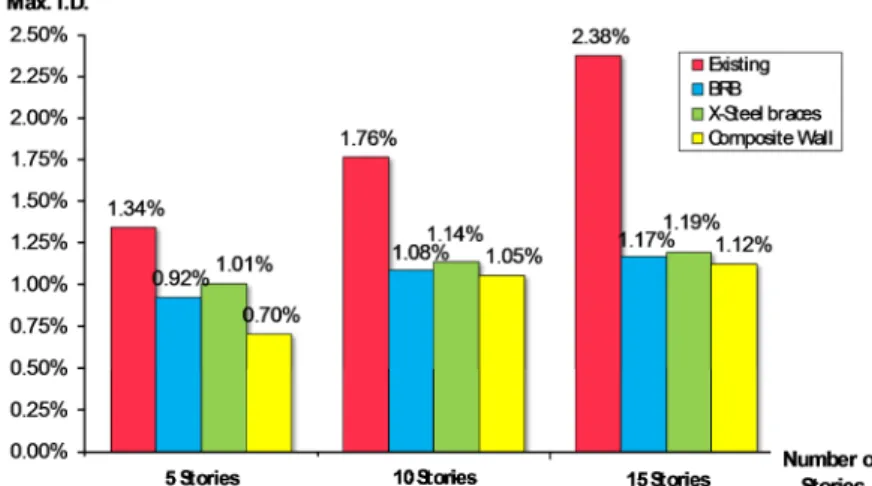
5.2. Maximum inter-story drift ratio
Fig. 6 shows the maximum Inter-story Drift (ID) ratio for existing and retrofitted buildings. During analyses, the existing frame buildings could not withstand 100% of
the design response spectrum intensity. Therefore, for existing buildings, the ID ratio shown in Fig. 6 was calculated at the maximum intensity that could be resisted by the buildings, which is 75%, 67%, and 59% of the design response spectrum for the 5-, 10-, and 15-story buildings, respectively. On the other hand, the retrofitted buildings were able to resist a 100% of the response spectrum intensity of the location considered.
Hence, the ID ratios of the retrofitted buildings were calculated at the full intensity of the design spectrum of San Francisco. This will be the case for all the following analysis results presented here.
Fig. 6. Maximum I.D. ratio for the 5-, 10-, and 15-story buildings
As previously mentioned, the inter-story drift for the retrofitted buildings was limited to 1.20%. This limit was set in order not to affect the non-structural elements and the existing gravity load resisting system. This limit was used to design the retrofit elements and to ensure the safety of existing steel frame elements. The figure shows that the selected retrofit schemes were able to reduce the maximum ID ratio for the three building heights to be less than 1.20% when subjected to the design spectrum of the location considered.
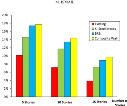
5.3. Maximum shear-to-weight ratio
Fig. 7 shows the base shear-to-weight ratio for existing buildings and retrofitted ones with different retrofit schemes. From the figure, it can be seen that the retrofit techniques resulted in a higher base shear compared to existing structures due to the additional stiffness provided by the retrofit. The figure shows that X-steel bracings resulted in the least base shear-to-weight ratio compared to other retrofit techniques for all building heights. The capacity curve of the structure Base Shear curve is a suitable tool for investigating overall behavior of the structure [16]. On the other hand, the composite plate shear walls resulted in highest base shear between the three retrofit techniques.
Fig. 7. Base shear-to-weight ratio for the 5-, 10-, and 15 story buildings
6. Cost of retrofit constitutive materials
Table II shows the weight of steel and the volume of concrete material used for the seismic retrofit of each building height and retrofit scheme. The values shown are used to estimate the total cost of retrofit material for each technique and each building height.
Based on a survey of construction material prices in California, USA, the average price of one ton of steel section material and one cubic meter of concrete material were found to be USD 2,200 $ and 250 $, respectively. Based on the aforementioned values, the total cost of the constitutive materials used for every retrofit scheme was obtained for each building height.
Table II
Quantities of seismic retrofit constitutive materials for the studied buildings
Material
No. of stories
X-Steel
braces BRB Composite Plate Shear Wall
Steel (ton)
5 15 11 15
10 70 52 45
15 208 115 180
Concrete (m3)
5 --- 11 80
10 --- 55 240
15 --- 310 720
In order to normalize the cost values, the total retrofit cost for each building was divided by the number of floors and these values were presented in Fig. 8. From the figure, it can be concluded that the BRB system was the most economical retrofit system for the three heights considered. The BRB system showed the least retrofit material cost among the three retrofit schemes, which is the most optimum engineering optimization [17]. This is due to the smaller steel sections used in the compression members due to restraining the brace against buckling with the help of the concrete section and the steel encasing. The cost saving is more visible for the 15-story building.
On the other hand, the composite concrete-steel plate shear wall showed the highest cost of retrofit material between the three systems for all building heights. Therefore, it can be concluded that the BRB retrofit scheme provided a lateral stiffness that is comparable to other retrofit schemes; meanwhile it attracted the least seismic forces between the three schemes. In addition, the BRB showed the least retrofit material cost compared to other techniques.
Fig. 8. Total cost of retrofit material per floor
It should be mentioned that the cost estimate did not include the cost of labor work of each technique. The estimate did not include the cost of foundation upgrade that might be needed because of the additional seismic forces due to retrofit. The conclusions derived here in this study are limited to buildings’ geometry similar to the studied buildings and for buildings located in high seismic hazard zones.
7. Conclusions
The effectiveness of different retrofit techniques in upgrading the seismic performance of steel frame structures was evaluated. Three steel buildings with different heights were selected. The frames were strengthened using three strengthening techniques, namely; using steel X-bracings, introducing Buckling Restrained Bracings (BRBs), and using composite concrete-steel plate shear walls. The seismic performance enhancement of the analyzed frame buildings was evaluated in terms of the building’s fundamental period, maximum inter-story drift ratio, and maximum story shear-to-
weight ratio. Moreover, the retrofit material cost was evaluated for each retrofit technique.
The conducted analyses have resulted in the following conclusions:
1. Existing frame buildings were not able to withstand a 100% of the design response spectrum intensity. They had a collapse mechanism at 75%, 67%, and 59% of the design spectrum of San Francisco city for the 5-, 10-, and 15-story buildings, respectively;
2. The fundamentals periods of retrofitted structures were less than those of existing structures due to the additional stiffness provided by the retrofit schemes;
3. The retrofitted buildings were able to withstand a 100% of the design response spectrum intensity within the ID limit of 1.2%;
4. The building’s additional stiffness decreases the building’s inter-story drift significantly compared to existing buildings;
5. The retrofit techniques increased the buildings’ base shear and overturning moment compared to existing buildings for the three different heights considered;
6. The composite concrete-steel plate shear wall system showed the least lateral deformations, and the highest attracted seismic forces between the three retrofit schemes;
7. The BRB system showed the least base shear and retrofit material cost for the three building heights considered. On the contrary, the composite concrete-steel plate shear wall showed the highest cost of retrofit material between the three retrofit schemes for the three building heights.
Open Access statement
This is an open-access article distributed under the terms of the Creative Commons Attribution 4.0 International License (https://creativecommons.org/licenses/by/4.0/), which permits unrestricted use, distribution, and reproduction in any medium, provided the original author and source are credited, a link to the CC License is provided, and changes - if any - are indicated. (SID_1)
References
[1] Recommended seismic design provisions for new moment frame buildings, Report FEMA 350, Federal Emergency Management Agency, Washington DC, 2000.
[2] ACI 318-1R-68 Manual of concrete practice, Part 2, American Concrete Institute, Detroit, USA, 1968.
[3] Yang C-S, Leon R. T., DesRoches R. Pushover response of a braced frame with suspended zipper struts, Journal of Structural Engineering, Vol. 134, No. 10, 2008, pp. 1619‒1626.
[4] Sabelli R., Mahin S., Chang C. Seismic demands on steel braced-frame buildings with buckling-restrained braces, Engineering Structures, Vol. 25, No. 5, 2003, pp. 655‒666.
[5] Uang C. M., Nakashima M. Steel buckling-restrained braced frames, Chapter 16 in Earthquake Engineering: Recent Advances and Applications, Y. Bozorgnia, V. V. Bertero, (Eds.) CRC Press, Boca Raton, FL, 2003.
[6] Usami T., Wang C., Funayamac J. Low-cycle fatigue tests of a type of buckling restrained braces, Procedia Engineering, Vol. 14, 2011, pp. 956‒964.
[7] Jose A. Sy., Naveed A. Aung T. H., Rayamajhi D. Application of buckling restrained braces in 50 storey building, International Journal of High Rise Buildings, Vol. 3, No. 1, 2014, pp. 81‒87.
[8] Astaneh-Asl A. Seismic studies of innovative and traditional composite shear walls, Research project in-progress, Dept. of Civil and Env. Engineering, Univ. of California, Berkeley, Sponsor: National Science Foundation; 1998–2000.
[9] Driver R. G., Abbas H. H., Sause R. Local buckling of grouted and ungrouted internally stiffened double-plate HPS webs, Journal of Constructional Steel Research, Vol. 58, No. 5-8, 2002, pp. 881–906.
[10] Ryu H., Chang S., Kim Y., Kim B. Crack control of a steel and concrete composite plate girder with prefabricated slabs under hogging moments, Engineering Structures, Vol. 27, No. 11, 2005, pp. 1613–1624.
[11] Analysis Reference Manual for SAP2000, ETABS, and SAFE, Computers and Structures Inc., California, USA, 2016.
[12] ASCE 7-10, Standard, Minimum design loads for buildings and other structures, American Society of Civil Engineering, USA, 2010.
[13] ACI 318M-08, Standard, Building requirements for structural concrete and commentary, American Concrete Institute, USA, 2008.
[14] ANSI/AISC 360-10, Standard, Specification for structural steel buildings, American Institute Code of Steel Construction, Chicago, IL, 2010.
[15] Brando G. Experimental tests on bracing type pure aluminum shear panels, Pollack Periodica, Vol. 2, No. 3, 2007, pp. 73‒84.
[16] Esposto M. FEM modeling of PTED beam-to column connections for earthquake resisting steel frames, Pollack Periodica, Vol. 2, No. 1, 2007, pp. 101‒112.
[17] Csébfalvi A. A hybrid meta-heuristic method for continuous engineering optimization, Periodica Polytechnica, Civil Engineering, Vol. 53, No. 2, 2009, pp. 93–100.
![Fig. 4. Seismic retrofit of the studied buildings using composite plate shear walls The existing and retrofitted buildings were analyzed using the design response spectrum of San Francisco city according to the ASCE 7-10 [12]](https://thumb-eu.123doks.com/thumbv2/9dokorg/792197.37178/6.892.183.640.317.623/seismic-retrofit-buildings-composite-retrofitted-buildings-francisco-according.webp)