Conditions
Gergely F. Samu,
†,‡Rebecca A. Scheidt,
†,§Prashant V. Kamat,*
,†,§and Csaba Janáky*
,‡,∥†Radiation Laboratory, University of Notre Dame, Notre Dame, Indiana 46556, United States
‡Department of Physical Chemistry and Materials Science, University of Szeged, Rerrich Square 1, Szeged, H-6720, Hungary
§Department of Chemistry and Biochemistry, University of Notre Dame, Notre Dame, Indiana 46556, United States
∥ELI-ALPS Research Institute, Szeged, Dugonics sq. 13, 6720, Hungary
*S Supporting Information
ABSTRACT: The unique optoelectronic properties of lead halide perovskites have triggered a new wave of excitement in materials chemistry during the past five years. Electrochemistry, spectroelectrochemistry, and photoelectrochemistry could be viable tools both for analyzing the optoelectronic features of these materials and for assembling them into hybrid architectures (e.g., solar cells). At the same time, the instability of these materials limits the pool of solvents and electrolytes that can be employed in such experiments. The focus of our study is to establish a stability window for electrochemical tests for all-inorganic CsPbBr3 and hybrid organic−inorganic MAPbI3 perovskites. In addition, we aimed to understand the reduction and oxidation events that occur and to assess the damage done during these processes at extreme electrochemical conditions. In this vein, we demonstrated the chemical, structural, and morphological changes of the films in both reductive and oxidative environments. Taking all these results together as a whole, we propose a set of boundary conditions and protocols for
how electrochemical experiments with lead halide perovskites should be carried out and interpreted. The presented results will contribute to the understanding of the electrochemical response of these materials and lead to a standardization of results in the literature so that comparisons can more easily be made.
■
INTRODUCTIONThe discovery of the intriguing optoelectronic properties of lead halide perovskites has created excitement in variousfields of materials science, especially in solar energy conversion.1,2 While the most prominent application avenue for these materials is in solar cells, where the current certified record efficiency is held at 22.1%,3they have shown great promise as light-emitting diodes,4 photodetectors,5 and lasers.6 The common virtue of all these applications is that charge carrier generation and transport are involved. Although electro- chemistry is a simple tool to probe charge carrier formation and transport, there is surprisingly little precedence in the literature on this matter. Electrochemical experiments would be powerful tools to study the rich solid state chemistry aspects of perovskites,7 where defects and grain boundaries as well as presence of minority phases could be monitored. In addition, investigation of the optoelectronic propertiesincluding determination of band edge positions and trap state density mappingwould be possible to perform using spectroelec- trochemistry. Electrochemical measurements could also con- tribute to the better understanding of chemical changes occurring at the various interfaces in perovskite solar cells.8 Finally, electrochemical synthetic techniques could provide new
opportunities to assemble complex perovskite based architec- tures.
The infancy of perovskite electrochemistry is most likely rooted in the instability of the material inalmost allcommonly used solvents and electrolytes. Recently, a few studies employed electrochemistry for different purposes, such as probing Li+ intercalation/deintercalation9,10and electrochemiluminescence measurements.11−13It was observed that charging/discharging studies need to be conducted with extreme caution because unintended side reactions may take place which would cause inaccuracies in the determined charge capacitance val- ues.9,10,14,15 Electrogenerated luminescence was reported with such materials, although the phenomenon is not fully understood yet.11−13In another recent paper, a solvent toolkit was proposed for these Li+intercalation experiments.16A very thorough study investigated the electron injection process into formamidinium lead halide perovskite using spectroelectro- chemistry.17It was demonstrated in this study that it is very difficult, yet possible, to probe band edge positions via charge
Received: October 16, 2017 Revised: December 1, 2017 Published: December 5, 2017
carrier injection. During these experiments, however, an irreversible electrochemical reduction occurred, thus making the picture even murkier.17 An overview of the possible solution chemistry events was given, although without taking into account the likely contribution of the electrolyte ions. A similar approach was followed for mixed CsPbX3(X = Cl, Br, and I) perovskites, where it was assumed that band edge positions can be simply determined from voltammetric data.18 The photoelectrochemical behavior of methylammonium lead iodide (MAPbI3) was probed in dichloromethane, in the presence of different reversible redox couples (e.g., ferrocene and benzoquinone). Cells showed high open-circuit voltage and remarkable stability for prolonged irradiation time in these systems.19,20 Electrochemical impedance spectroscopy and Mott−Schottky analysis was also performed to estimate the charge carrier density and flatband potential of different optically active perovskites.19,21 Most recently, we demon- strated the use of transient absorption spectroscopy under electrochemical control.22
Despite the above examples, solid and coherent knowledge about the fundamental electrochemical behavior of these materials is missing. Thus, the interpretation of results can be challenging. In this paper, the electrochemical behavior of the two most frequently studied perovskites (MAPbI3 and CsPbBr3) is scrutinized in conventional electrolytes. The stability window was established, and the products formed during the redox transformation of these materials were analyzed. Elaborating on these results, guidelines are given to perform different (photo)electrochemical experiments, which can be later exploited in solar fuel generation or for the electrodeposition of a hole transporter material.
■
EXPERIMENTAL SECTIONElectrode Preparation. To study practically relevant electrodes as model systems, CsPbBr3 and MAPbI3 were immobilized on TiO2-coated fluorine doped tin oxide (FTO) glass electrodes, thus mimicking the commonly used architecture in perovskite solar cells. During the electro- chemical experiments, dichloromethane (DCM) was used as solvent while tetrabutyl ammonium tetrafluoroborate (Bu4NBF4), tetrabutyl ammonium perchlorate (Bu4NClO4), and tetrabutyl ammonium hexafluorophosphate (Bu4NPF6) were used as conducting electrolytes. All of these chemicals were carefully dried before use as described in theSupporting Information.
The electrode preparation process is detailed in the Supporting Information. Briefly, it comprises the following
steps. First, a TiO2 blocking layer followed by a mesoporous TiO2layer was spin-coated on FTO slides. Subsequently, the FTO/bl-TiO2/mp-TiO2 samples23 were subjected to a TiCl4 treatment step. The fabrication of the FTO/TiO2/MAPbI3 electrodes followed the Lewis base adduct method.24 The perovskite layers were obtained via the one-step method where the precursors were dissolved in dimethylformamide and were then spin-coated onto the FTO/bl-TiO2/mp-TiO2substrates.
A hot injection method was used with Cs-oleate and PbBr2 precursors to synthesize CsPbBr3 nanocrystals (NCs).25 Finally, bulk films were formed using subsequent deposition of the NCs on the substrate as demonstrated in previous reports.25 The perovskite-coated electrodes were freshly prepared and kept in a glovebox before use.
Characterization Methods.Steady state UV−vis absorp- tion spectra of the prepared electrodes were recorded with a Cary 50 Bio spectrophotometer (Varian). X-ray diffraction (XRD) patterns were collected using a Bruker D8 DISCOVER instrument with Cu Kα X-ray source (λ = 1.5406 Å), in the 20−80°range, with a 2°min−1scan rate. Top-down and cross- sectional scanning electron microscopic (SEM) images were captured using a FEI Helios NanoLab DualBeam instrument.
X-ray photoelectron spectra were acquired with a PHI VersaProbe II system. The binding energy scale was corrected byfixing the main C 1s component to 284.8 eV, corresponding to the adventitious carbon. For spectrum acquisition and evaluation, the MultiPak software was used. To fit the XP spectra and determine the elemental composition of the different samples a Shirley background was used. First the spectra of the pure CsPbBr3 samples was fitted. From these fittings the profile shape, position, and full width at half maximum (FWHM) of thefitting functions were determined.
For the electrochemically treated samples these fittings functioned as starting parameters, from which the shape and FWHM was held constant for each subsequent fitting. Small variation in the peak position was allowed for eachfit. If the fitting was inadequate, another component was added to the process.
The electrochemical measurements were carried out with a Gamry potentiostat in a standard three-electrode setup (see the schematics of the setup in Scheme S1.). The FTO/TiO2/ perovskite electrodes functioned as the working electrode, a Pt mesh (1 cm2) as the counterelectrode (cleaned by “Piranha solution”, water, andfinally DCM), and a Ag/AgCl wire as a pseudoreference electrode. The homemade Ag/AgCl pseudor- eference electrode was a Ag wire having AgCl deposited on its surface. This is generally applied in organic media, because it Figure 1.(A) Normalized absorbance change at 518 nm of FTO/TiO2/CsPbBr3electrode in DCM containing different electrolytes. The error bars were derived from measurements on three separate films. (B) and (C) show representative UV−vis spectra recorded before and after 30 min exposure to 0.1 Bu4NBF4/DCM and 0.1 Bu4NPF6/DCM solutions, respectively.
can be considered as a secondary electrode, with very low chloride ion concentration. Its potential was calibrated before and after the experiments, by measuring the formal potential of the ferrocene/ferrocenium redox couple in dichloromethane (0.01 M ferrocene and 0.1 M Bu4NPF6). Cyclic voltammetry was used, and the formal potential was found to beE= 0.45± 0.04 V vs our Ag/AgCl. All cells were assembled in a glovebox (N2atmosphere, H2O < 0.1 ppm, O2 < 0.1 ppm) and sealed hermetically to ensure inert conditions.
■
RESULTS AND DISCUSSIONAfter screening a large pool of solvents and electrolytes, we concluded that dichloromethane (DCM) is a viable candidate.
Most perovskites are stable in this medium, and it readily dissolves commonly employed electrolytes. To probe the stability of thefilms, a series of UV−vis spectra was recorded in pure DCM as well as in each electrolyte for a period of 60 min (Figure S1). Normalized absorbance traces, measured at 518 nm (the excitonic peak of CsPbBr3), are compared inFigure 1A for the different electrolytes. After an initial absorbance increase, where thefilm becomes cloudy and slightly opaque, thefilms begin to dissolve. The rate of dissolution is related to the complexing ability of the anions as well as the specific interactions between the different anions in the solution and the cations in the perovskite lattice.26,27The following definite trend was found in the dissolution rate: BF4−> ClO4−≫PF6−. Based on these observations, we have chosen Bu4NPF6for all further experiments. We note here that even trace amounts of water can completely ruin the stability of these samples (in our experiments the water content was always kept below 10 ppm).
Therefore, electrochemical experiments involving lead halide perovskites should be conducted in an inert environment. This can be achieved by completing measurements either inside of a glovebox or inside of a sealed electrochemical cell that has been thoroughly purged. The latter option was used for all experiments discussed in this paper. Additionally, the water content of not only the pure solvents but also the solutions needs to be checked (e.g., by Karl Fischer titration), and additional drying steps should be employed if necessary.
In the next step, two separate spectroelectrochemical experiments were carried out, where the potential was scanned from the open circuit potential (OCP) value to both anodic and cathodic directions. Under positive (anodic) bias, thefirst oxidation wave was situated at 0.8 V, followed by a second oxidation peak starting at 1.3 V. In fact, this second wave is a sum of two peaks, as seen from the shoulder in Figure 2A.
These redox events are reflected in distinct changes that occur in the optical behavior. During oxidation, the absorbance
increased below 530 nm in the first oxidation step with the onset of ∼0.6 V. The shape of the absorbance increase (i.e., difference absorbance spectrum) mirrors the initial spectrum of the electrode which indicates that the perovskite structure is preserved in thefilm even with a surface etching phenomenon occurring which causes this increase in absorbance (Figure S2).
In addition, the absorbance increase (and opacity) witnessed upon immersion into 0.1 M Bu4NPF6 is also very similar (Figure S2). Overall, we think that this absorbance increase is not rooted in the formation of a new material, but in other physical factors (e.g., scattering) which enhance the absorption of the perovskite film. The absorbance drastically decreased during the second step (onset∼1.3 V). As for the reduction, there was a single redox peak centered at−1.4 V, where notably higher current densities were measured compared to the oxidative events. As a result of the reduction, there was a rapid decrease in the absorbance at the excitonic peak characteristic to the perovskite material (Figure 2B). In parallel, there was an increased noncharacteristic absorption in the whole wavelength range (Figure S3), which was also confirmed by the reflective metallic appearance of thefilm (Figure 2C).
The question naturally comes whether these peaks correspond to Faradaic events (i.e., reduction of ions) or they are simply related to electron and hole injection into the conduction and valence bands (CB and VB), respectively, and, thus, represent band energy values. To probe the possible changes in the CsPbBr3structure, the electrodes were polarized atE=−1.4 V, +0.8 V, and +1.5 V for 30 s in 0.1 M Bu4NPF6/ DCM solution. After carefully washing the electrodes with DCM and drying them in an argon stream, XPS measurements were carried out to analyze the chemical composition of the surface. Several important trends can be revealed by the careful analysis of the XPS spectra (Figure 3): (i) the intensity of the Br−-related signal decreased during all treatments and a new species developed during the reduction; (ii) the F− signal emerged upon oxidation and this trend was more pronounced for samples treated at more positive potentials; (iii) in parallel, a new electron-rich form of Cs+ developed for the oxidized samples; and (iv) a new form of oxygen arose in the reduced sample (in addition to the adsorbed oxygen moieties).
Taking these trends together as a whole, we propose the following explanations. The obvious reduction reaction is the formation of Pb at negative potentials (as also confirmed by SEM−EDX analysis, shown later). Pb is partially reoxidized to PbO upon air exposure while preparing the electrode for XPS measurements, confirmed by both the Pb and the O signals.
During oxidation, the Br−and Pb2+content is gradually lost due to the destruction of the CsPbBr3structure. In parallel the F− Figure 2.Spectroelectrochemical data, recorded for FTO/TiO2/CsPbBr3films in 0.1 M Bu4NPF6/dichloromethane electrolyte (10 mV s−1sweep rate), during the (A) oxidation and (B) reduction half cycle together with the absorbance change at the excitonic peak. (C) shows photographs of electrodes treated at selected potential values for 30 s.
content (with a binding energy typical for PF6−) increased significantly, suggesting the formation of CsPF6on the surface.
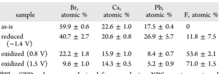
This notion was further confirmed by SEM−EDX, which demonstrated the P content in the oxidized samples. These trends are quantified inTable 1, where the surface composition of the various samples is presented. The larger dispersion in the case of the reduced electrodes further confirmed the inhomogeneity of these samples, to be shown later on the SEM images.
To quantify the above-mentioned trends, we deconvoluted the spectra inFigure 3, which allowed for quantitative analysis
of the surface composition, and specifically to determine the amount of the various species. For example, upon the oxidation of CsPbBr3, we assume the formation of CsPF6. By analyzing the Cs 3d region, two distinct species were identified. By assigning the ones at 738.3 and 724.3 eV to CsPbBr3and the ones at 739.6 and 725.2 eV to CsPF6, we calculated the theoretical Br−, F−, and Pb2+ content (Table S2). As seen in Table S2, a very good match was found between the measured and the calculated data.
To further confirm the above conclusions, XRD analysis was also performed. We consider XPS analysis to be more Figure 3.High resolution XPS data for the FTO/TiO2/CsPbBr3electrodes treated at selected potential values (as is,−1.4 V, +0.8 V, +1.5 V), for 30 s in 0.1 M Bu4NPF6/dichloromethane solution.
informative, due to the very small thickness of the films employed in this study. In addition, because of the complexity of the system and the large number of possible corrosion products, there are notable overlaps among the various diffractions. Because of these two factors, we only make qualitative conclusions, which are in line with the XPS data presented above.Figure 4 shows the XRD patterns of FTO/
TiO2/CsPbBr3electrodes, held at the same potential values as those presented inFigure 3. The characteristic diffraction peaks of CsPbBr3were identified on all diffractograms at 15.3°, 21.7°, 26.6°, 30.8°, and 33.8°2Θvalues.25Upon oxidation, a gradual decrease was witnessed in the intensity of these diffractions (Figure 4A), although because of the overlap of several diffractions this is not trivial for thefirst view. In addition, low intensity diffractions related to CsPF6developed at 2Θ= 21.6, 30.7, and 36.4 (PDF: 00-034-0506). Note that the elemental composition deduced from XPS data semiquantitatively confirmed the formation of CsPF6. A substantial decrease in the intensity of the diffractions associated with CsPbBr3 was seen as a result of the cathodic treatment. In addition, PbO- related diffraction peaks appeared (PDF: 00-085-1288), suggesting that the formed Pb is readily reoxidized to PbO upon air exposure.28 Based on the above observations, the plausiblereactions 1−3are summarized below:
Oxidation:
− −→ + ++
CsPbBr3 e PbBr2 Cs 0.5Br2 (1)
− −→ + +
PbBr2 2e Pb2 Br2 (2)
only negligible amounts of F− were detected (due to physisorbed PF6−), and the Br, Cs, Pb, and O elements were of identical chemical nature to those in the pristine sample (Figure S4). The quantitative surface composition analysis also supported these qualitative observations (Table S3).
The morphological changes that occurred during the redox events were visualized using SEM and SEM−FIB (to capture side-view images). The top view and cross-section images are compiled in Figure 5. The pristine sample has the granular morphology typically seen for CsPbBr3 (Figure 5A), and it remains almost intact under mild electrochemical conditions (Figure S5). When the electrodes were exposed to more extreme electrochemical conditions (under the same circum- stances as the samples discussed above), notable changes happened. Upon reduction, the particulate morphology disappeared and a compact film was formed at certain areas of the electrode (Figure 5B and Figure S6). At lower magnification, we could even observe formation of dendrites, and EDX analysis confirmed that the dendrites are made of Pb (Figure S6). During oxidation, rectangular particles were formed, which grew with the increasing potential (Figure 5C,D). For the sample held at 1.5 V bias potential, the underlying mesoporous TiO2 became visible because of the destruction of the original perovskitefilm (Figure 5D). What is common in all cases is that the initial compactfilm turns into a porous one. Thus, the applied potential impacts the morphological changes to different extents (Figure 5 E−H).
The side-view images provide similar insights: (i) the CsPbBr3 disappears at certain areas and the TiO2 becomes visible and (ii) a hollow structure is formed upon oxidation (Figure 5G and H), due to the dissolution of the perovskite.
To better understand the nature of these redox trans- formations, control experiments were carried out with FTO/
The STD values were derived from analyzing XPS spectra captured from three different spots of the sample.
Figure 4.(A) XRD patterns for the FTO/TiO2/CsPbBr3electrodes treated at selected potential values (as is,−1.4 V, +0.8 V, +1.5 V) for 30 s in 0.1 M Bu4NPF6/dichloromethane solution. The peaks marked with#represent overlapping diffractions of CsPbBr3and the FTO/TiO2substrate. (B) Magnified regions of the diffraction patterns of the samples held at−1.4 V and +0.8 V. The peaks marked with*belong to the untreated FTO/
TiO2/CsPbBr3electrodes.
TiO2and FTO/TiO2/PbBr2films (Figure S7). The PbBr2was more resistant toward oxidation, as the FTO/TiO2/PbBr2was stable up to 1.6 V (vs 0.7 V in the case of CsPbBr3). This suggests that only the third oxidation peak in Figure 2A is related to either PbBr2 or the substrate, while the other two waves (at less positive potentials) are characteristic to CsPbBr3. As for the reduction, a more interesting trend was seen: the CsPbBr3was more stable than PbBr2, as this latter was reduced at 450 mV less negative potential.
To see whether the observed behavior is unique to CsPbBr3 or if it is more general, we extended our study to MAPbI3. Largely, the stability of thefilms was worse in all electrolytes
studied in the present investigation (Figure 6A andFigure S8).
However, the degradation trend at both positive and negative bias was the same as in the case of CsPbBr3. In addition, the initial absorbance increase (and any opacity) was not seen in this case. Since the stability obtained in 0.1 M Bu4NPF6 solution was still not ideal, the electrolyte concentration was decreased to 0.01 M through which a reasonable lifetime was ensured (Figure 6A). Spectroelectrochemical studies revealed two oxidation and one reduction steps, atE= +0.8 V, +1.1 V, and−0.75 V, respectively. Careful inspection of the cathodic wave revealed a shoulder atE=−0.95 V. These redox events were coupled with a massive decrease in the absorbance related Figure 5.SEM images of CsPbBr3films both from the top and side views. (A, E) Pristine; (B, F) reduced atE=−1.4 V; (C, G) oxidized atE= 0.8 V, (D, H) oxidized atE= 1.4 V. All treatments lasted 30 s in 0.1 M Bu4NPF6/dichloromethane solution.
Figure 6.(A) Kinetic curves of the normalized absorbance change at 470 nm, recorded for FTO/TiO2/MAPbI3in different electrolytes. The error bars were derived from the measurement of three separatefilms. Spectroelectrochemical data, recorded for FTO/TiO2/MAPbI3 films in 0.1 M Bu4NPF6/dichloromethane solution (10 mV s−1sweep rate), during the (B) oxidation and (C) reduction half cycles together with the absorbance changes at 470 nm.
Figure 7.Comparison of the band edge positions and the potential of various redox events detected for the studied two lead halide perovskites.
redox events, deduced from the spectroelectrochemical studies.
The position of the redox events was always calculated from the onset potential of the redox waves. The band edge positions of the perovskite materials were obtained from previous literature data and serve semiquantitative comparison, because the film preparation methods were not identical.29,30 This representa- tion, together with the previously demonstrated structural analysis, allows the initial question of whether the currents measured during the voltammetric curves are related to charge carrier injection into the materials and/or to real Faradaic events to be answered. As for CsPbBr3, a good match can be revealed between the potential of the reduction peak and the CB edge as well as the second oxidation peak and the VB edge.
More interestingly, the first oxidation peak occurs at a less positive potential than the VB, meaning that the CsPbBr3 is irreversibly oxidized before hole injection can take place. Based on all the evidence gathered in this study, these potential values should be considered as cathodic and anodic corrosion potentials, respectively. There is a comparable situation in the case of MAPbI3, but here the second reduction peak matches the potential of the CB. This means that an irreversible chemical transformation occurs before the CB can be populated with electrons. These observations highlight the difference between the solar- and electrochemical cell scenarios because, in a solar cell, the photogenerated holes (in the case of CsPbBr3) and the electrons (in the case of MAPbI3) do not corrode the electrode material as they are transferred quickly to electron and hole transport layers (ETL and HTL). If not scavenged quickly, these electrons and holes can induce degradation based on the energy levels illustrated inFigure 7.
Addition of an electron acceptor (redox mediator) to the solution can also increase the stability in a similar manner.17
Best Practice for Pursuing Electrochemical Experi- ments with Metal Halide Perovskites. To conduct electrochemical studies with metal halide perovskites in a reliable manner, the experiments need to comply with the basic principles of electrochemistry. One needs to carefully make the choice of the solvent, electrolyte, and electrochemical window to ensure the stability of the electrode within the time frame of the experiment. Given the sensitivity of perovskite films to polar solvents, one needs to exercise caution while drawing conclusions from the studies performed in aqueous media.11,12 It should also be noted that conclusions obtained with certain special electrolytes, such as Li+ or reversible redox couples19 which are pertinent to certain specific applications, cannot be simply generalized. The researchers should provide data to support the stability test by monitoring the absorption and/or performing surface spectroscopy measurements before and after electrochemical measurements. This is the only way to ensure that the observed redox processes are chemically reversible. However, there is a safe electrochemical window to conduct electrochemical experiments. Based on ourfindings
In addition to the experimental considerations, careful analysis of the results is equally important. First of all, the electrochemical processes behind the measured redox waves must be clearly identified to draw meaningful conclusions. It should be decided whether the current response reflects a chemical (faradaic) process or simple charging/discharging (i.e., electron or hole injection). If it is a chemical process, one should study its chemical and electrochemical reversibility.
Similarly, it should be clarified whether it is a redox process limited by mass-transport from the solution or a surface confined one. If there is certainly no process other than charge injection, then voltammetric curves can be employed to determine band edge positions. Similar to organic semi- conductors,31 however, the onsets of the redox peaks17 and not the position of the peak maxima18have to be correlated with the respective band edge positions. Finally, during prolonged experiments migration of mobile ions within the perovskite structure might also happen thus complicating the picture even further.32
■
CONCLUSIONSIn this study, we assessed the stability window of two different lead halide perovskites (CsPbBr3 and MAPbI3) and analyzed the chemical changes during the anodic and cathodic redox waves. This is a crucially important exercise to perform before conducting any electrochemical experiment, such as Li+ ion incorporation or photoelectrochemical studies. The two representative optically active perovskites show the importance of a case by case analysis that is necessary for each perovskite− electrolyte−solvent system. The complex solution and solid- state chemistry dictates the stability window of the given system. It is very important to underline that simple CV scans alone can hardly be employed to determine the band edge positions of these materials. To do so, one must be convinced that there is no other redox event associated with the redox peaks. Overall, under carefully planned conditions it is possible to study the electrochemical behavior of these materials and to gain a better understanding of their unique optoelectronic properties.
window Ag/AgCl Ag/AgCl
solvent dichloromethane dichloromethane
electrolyte Bu4NPF6,≤0.1 M Bu4NPF6,≤0.01 M time window
(maximum)
two hours one hour
electrode substrate FTO, FTO/TiO2, glassy carbon
FTO, FTO/TiO2, glassy carbon
■
ASSOCIATED CONTENT*S Supporting Information
The Supporting Information is available free of charge on the ACS Publications website at DOI: 10.1021/acs.chemma- ter.7b04321.
UV−vis spectra recorded in different electrolytes, additional spectroelectrochemical data, additional SEM images and XPS data, and control measurements with PbBr2and PbI2(PDF)
■
AUTHOR INFORMATION Corresponding Authors*(P.V.K.) E-mail:pkamat@nd.edu.
*(C.J.) E-mail:janaky@chem.u-szeged.hu.
ORCID
Prashant V. Kamat:0000-0002-2465-6819
Csaba Janáky:0000-0001-5965-5173 Notes
The authors declare no competingfinancial interest.
■
ACKNOWLEDGMENTSThe authors thank Dr. Tatyana Orlova for taking the SEM images, Steven M. Kobosko for recording the XPS spectra, and Dr. Allen G. Oliver for recording the XRD patterns. We thank the ND Energy Materials Characterization Facility (MCF) for the use of the PHI VersaProbe II system. The MCF is funded by the Sustainable Energy Initiative (SEI), which is part of the Center for Sustainable Energy at Notre Dame (ND Energy).
This project has received funding from the European Research Council (ERC) under the European Union’s Horizon 2020 research and innovation program (Grant Agreement No.
716539). ELI-ALPS is supported by the European Union and cofinanced by the European Regional Development Fund (GOP-1.1.1-12/B-2012-000, GINOP-2.3.6-15-2015-00001).
The authors also thank Rendernet Ltd. for assistance in preparing the artwork in the TOC. P.V.K. acknowledges the support by the Division of Chemical Sciences, Geosciences, and Biosciences, Office of Basic Energy Sciences, of the U.S.
Department of Energy, through award DE-FC02-04ER15533.
R.A.S. acknowledges the support of King Abdullah University of Science and Technology (KAUST) through Award OCRF- 2014-CRG3-2268. This is NDRL No. 5190 from Notre Dame Radiation Laboratory.
■
(1) Manser, J. S.; Christians, J. A.; Kamat, P. V. IntriguingREFERENCES Optoelectronic Properties of Metal Halide Perovskites. Chem. Rev.2016,116, 12956−13008.
(2) Park, N.-G. Organometal Perovskite Light Absorbers Toward a 20% Efficiency Low-Cost Solid-State Mesoscopic Solar Cell.J. Phys.
Chem. Lett.2013,4, 2423−2429.
(3) Yang, W. S.; Park, B.-W.; Jung, E. H.; Jeon, N. J.; Kim, Y. C.; Lee, D. U.; Shin, S. S.; Seo, J.; Kim, E. K.; Noh, J. H.; Seok, S. Il. Iodide Management in Formamidinium-Lead-Halide−based Perovskite Layers for Efficient Solar Cells.Science2017,356, 1376−1379.
(4) Cho, H.; Jeong, S.-H.; Park, M.-H.; Kim, Y.-H.; Wolf, C.; Lee, C.- L.; Heo, J. H.; Sadhanala, A.; Myoung, N.; Yoo, S.; Im, S. H.; Friend, R. H.; Lee, T.-W. Overcoming the Electroluminescence Efficiency Limitations of Perovskite Light-Emitting Diodes. Science2015,350, 1222−1225.
(5) Fang, Y.; Dong, Q.; Shao, Y.; Yuan, Y.; Huang, J. Highly Narrowband Perovskite Single-Crystal Photodetectors Enabled by Surface-Charge Recombination.Nat. Photonics2015,9, 679−686.
(6) Zhu, H.; Fu, Y.; Meng, F.; Wu, X.; Gong, Z.; Ding, Q.;
Gustafsson, M. V.; Trinh, M. T.; Jin, S.; Zhu, X.-Y. Lead Halide Perovskite Nanowire Lasers with Low Lasing Thresholds and High Quality Factors.Nat. Mater.2015,14, 636−642.
(7) Manser, J. S.; Saidaminov, M. I.; Christians, J. A.; Bakr, O. M.;
Kamat, P. V. Making and Breaking of Lead Halide Perovskites.Acc.
Chem. Res.2016,49, 330−338.
(8) Zhao, L.; Kerner, R. A.; Xiao, Z.; Lin, Y. L.; Lee, K. M.; Schwartz, J.; Rand, B. P. Redox Chemistry Dominates the Degradation and Decomposition of Metal Halide Perovskite Optoelectronic Devices.
ACS Energy Lett.2016,1, 595−602.
(9) Dawson, J. A.; Naylor, A. J.; Eames, C.; Roberts, M.; Zhang, W.;
Snaith, H. J.; Bruce, P. G.; Islam, M. S. Mechanisms of Lithium Intercalation and Conversion Processes in Organic−Inorganic Halide Perovskites.ACS Energy Lett.2017,2, 1818−1824.
(10) Jiang, Q.; Chen, M.; Li, J.; Wang, M.; Zeng, X.; Besara, T.; Lu, J.; Xin, Y.; Shan, X.; Pan, B.; Wang, C.; Lin, S.; Siegrist, T.; Xiao, Q.;
Yu, Z. Electrochemical Doping of Halide Perovskites with Ion Intercalation.ACS Nano2017,11, 1073−1079.
(11) Huang, Y.; Fang, M.; Zou, G.; Zhang, B.; Wang, H.
Monochromatic and Electrochemically Switchable Electrochemilumi- nescence of Perovskite CsPbBr3 Nanocrystals. Nanoscale 2016, 8, 18734−18739.
(12) Tan, X.; Zhang, B.; Zou, G. Electrochemistry and Electro- chemiluminescence of Organometal Halide Perovskite Nanocrystals in Aqueous Medium.J. Am. Chem. Soc.2017,139, 8772−8776.
(13) Huang, Y.; Long, X.; Shen, D.; Zou, G.; Zhang, B.; Wang, H.
Hydrogen Peroxide Involved Anodic Charge Transfer and Electro- chemiluminescence of All-Inorganic Halide Perovskite CsPbBr3 Nanocrystals in an Aqueous Medium. Inorg. Chem. 2017, 56, 10135−10138.
(14) Vicente, N.; Garcia-Belmonte, G. Methylammonium Lead Bromide Perovskite Battery Anodes Reversibly Host High Li-Ion Concentrations.J. Phys. Chem. Lett.2017,8, 1371−1374.
(15) Tathavadekar, M.; Krishnamurthy, S.; Banerjee, A.; Nagane, S.;
Gawli, Y.; Suryawanshi, A.; Bhat, S.; Puthusseri, D.; Mohite, A. D.;
Ogale, S. Low-Dimensional Hybrid Perovskites as High Performance Anodes for Alkali-Ion Batteries.J. Mater. Chem. A2017,5, 18634− 18642.
(16) Hasan, M.; Venkatesan, S.; Lyashenko, D.; Slinker, J. D.;
Zakhidov, A. Solvent Toolkit for Electrochemical Characterization of Hybrid Perovskite Films.Anal. Chem.2017,89, 9649−9653.
(17) Shallcross, R. C.; Zheng, Y.; Saavedra, S. S.; Armstrong, N. R.
Determining Band-Edge Energies and Morphology-Dependent Stability of Formamidinium Lead Perovskite Films Using Spectroelec- trochemistry and Photoelectron Spectroscopy.J. Am. Chem. Soc.2017, 139, 4866−4878.
(18) Ravi, V. K.; Markad, G. B.; Nag, A. Band Edge Energies and Excitonic Transition Probabilities of Colloidal CsPbX3(X = Cl, Br, I) Perovskite Nanocrystals.ACS Energy Lett.2016,1, 665−671.
(19) Hsu, H.; Ji, L.; Ahn, H. S.; Zhao, J.; Yu, E. T.; Bard, A. J. A Liquid Junction Photoelectrochemical Solar Cell Based on p-Type MeNH3PbI3Perovskite with 1.05 V Open-Circuit Photovoltage.J. Am.
Chem. Soc.2015,137, 14758−14764.
(20) Hsu, H.; Ji, L.; Du, M.; Zhao, J.; Yu, E. T.; Bard, A. J.
Optimization of PbI2/MAPbI3 Perovskite Composites by Scanning Electrochemical Microscopy. J. Phys. Chem. C 2016, 120, 19890−
19895.
(21) Li, Z.; Mercado, C. C.; Yang, M.; Palay, E.; Zhu, K.
Electrochemical Impedance Analysis of Perovskite−electrolyte Inter- faces.Chem. Commun.2017,53, 2467−2470.
(22) Scheidt, R. A.; Samu, G. F.; Janaky, C.; Kamat, P. V. Modulatioń of Charge Recombination in CsPbBr3 Perovskite Films with Electrochemical Bias. J. Am. Chem. Soc. 2017, DOI: 10.1021/
jacs.7b10958.
(23) Neale, N. R.; Frank, A. J. Size and Shape Control of Nanocrystallites in Mesoporous TiO2 Films. J. Mater. Chem. 2007, 17, 3216−3221.
43, 2066−2090.
(28) Sawatani, S.; Ogawa, S.; Yoshida, T.; Minoura, H. Formation of Highly Crystallizedβ-PbO Thin Films by Cathodic Electrodeposition of Pb and Its Rapid Oxidation in Air.Adv. Funct. Mater. 2005,15, 297−302.
(29) Akkerman, Q. A.; Gandini, M.; Di Stasio, F.; Rastogi, P.;
Palazon, F.; Bertoni, G.; Ball, J. M.; Prato, M.; Petrozza, A.; Manna, L.
Strongly Emissive Perovskite Nanocrystal Inks for High-Voltage Solar Cells.Nat. Energy2016,2, 16194.
(30) Schulz, P.; Edri, E.; Kirmayer, S.; Hodes, G.; Cahen, D.; Kahn, A. Interface Energetics in Organo-Metal Halide Perovskite-Based Photovoltaic Cells.Energy Environ. Sci.2014,7, 1377−1381.
(31) Cardona, C. M.; Li, W.; Kaifer, A. E.; Stockdale, D.; Bazan, G. C.
Electrochemical Considerations for Determining Absolute Frontier Orbital Energy Levels of Conjugated Polymers for Solar Cell Applications.Adv. Mater.2011,23, 2367−2371.
(32) Bandiello, E.; Ávila, J.; Gil-Escrig, L.; Tekelenburg, E.; Sessolo, M.; Bolink, H. J. Influence of Mobile Ions on the Electroluminescence Characteristics of Methylammonium Lead Iodide Perovskite Diodes.J.
Mater. Chem. A2016,4, 18614−18620.