Photocorrosion at Irradiated Perovskite/Electrolyte Interfaces
Gergely F. Samu* and Csaba Janáky*
Cite This:J. Am. Chem. Soc.2020, 142, 21595−21614 Read Online
ACCESS
Metrics & More Article Recommendations*
sı Supporting InformationABSTRACT:
Metal
−halide perovskites transformed optoelectronics research and development during the past decade. They have also gained a foothold in photocatalytic and photoelectrochemical processes recently, but their sensitivity to the most commonly applied solvents and electrolytes together with their susceptibility to photocorrosion hinders such applications. Understanding the elementary steps of photocorrosion of these materials can aid the endeavor of realizing stable devices. In this Perspective, we discuss both thermodynamic and kinetic aspects of photocorrosion processes occurring at the interface of perovskite photocatalysts and photoelectrodes with di
fferent electrolytes. We show how combined in situ and operando electrochemical techniques can reveal the underlying mechanisms. Finally, we also discuss emerging strategies to mitigate photocorrosion (such as surface protection, materials and electrolyte engineering, etc.).
1. INTRODUCTION
Photovoltaic (PV), photocatalytic (PC), and photoelectro- chemical (PEC) systems o
ffer the promise to e
fficiently convert solar energy either directly to electricity or to industrially relevant chemicals and fuels.
1The active component is a semiconductor (SC) that can generate free charge carriers under illumination with higher energy than the bandgap (hv
≥EBG).
The major di
fferentiator between PV and PC/PEC applications is the type of interfaces employed to extract and utilize these charge carriers. In PC/PEC devices, a SC/liquid interface is present that adds more functionality (and complexity) compared to the solid/solid interfaces in PV technologies.
Even though the pioneering studies on illuminated SC/liquid interfaces date back to the 1970s, an industrially relevant photocatalyst/photoelectrode still remains elusive (apart from the use of TiO
2-coated self-cleaning surfaces).
2Metal-halide perovskites (referred to as perovskites) possess optoelectronic properties that makes them ideal in solar energy harvesting, such as large extinction coe
fficient,
3,4large carrier di
ffusion length and lifetime,
5,6tunable bandgap,
7,8and mild synthesis conditions.
9Perovskite PVs have already reached a certi
fied e
fficiency of 25.5%, which can be boosted to 29.1%
when applied in tandem with Si.
10This performance, however, has not been translated to their photocatalyst/photoelectrode counterparts.
11Unfortunately, perovskites are extremely sensitive to most environmental factors (e.g., oxygen, moisture, heat, UV light, and especially the combination of these),
12and this instability still inhibits and complicates their practical use (even in the
field of PVs). Degradation of perovskites is generally considered to be a surface- or interface-initiated process that propagates toward the bulk material.
13,14So far, the composition and morphology of the perovskite layer (grain boundaries),
15choice of device constituents (charge extraction, electrode, and encapsulation layers)
16and the passivation of various interfacial defects were scrutinized in this regard.
17Charge extraction layer/perovskite interfaces also in
fluence the corrosion path- ways.
14,18UV light activated surface trap states of TiO
2,
19the
surface hydroxyl groups of ZnO,
20or the interaction with the dopants from the organic hole-extraction layers are all relevant examples.
21The e
ffect of these factors on the stability and performance of PC/PEC systems is yet to be understood, not even mentioning the role of liquid electrolyte present.
Decomposition pathways of perovskites are regarded as purely chemical in nature, involving at least one external reactant species (such as H
2O or O
2).
18Light can further accelerate the decomposition process (by photogenerated charge carriers) or even open additional degradation pathways (that involve redox reactions).
22,23Furthermore, under operating conditions, the presence of electric
field and the accumulation of charge carriers at di
fferent interfaces cannot be neglected.
14,24,25Notably, signi
ficant ion tra
ffic was observed even in the case of solid/solid interfaces. While the perovskite constituents often migrate deep into the charge extraction layers, reactive degradation products (such as I
2) can corrode the back contacts, leading to device failure.
26,27Simultaneously, the organic cations (such as CH
3NH
3+(MA
+)) can be electrochemically reduced forming volatile products.
25In the case of PC/PEC devices, a further complication arises because of mass transfer through the SC/
liquid junction. Specifically, migrating ions can leave the perovskite lattice and dissolve in the solution, making the light-driven processes irreversible.
28−31Combined electro- chemical techniques are powerful tools to study these corrosion events in a fast and reliable manner. Once the elementary processes are uncovered, e
ffective corrosion-mitigation strat- egies can be developed.
While photocorrosion studies on perovskites are still absent, much can be learned from precedent work on other SCs.
32Received: September 28, 2020 Published: December 18, 2020
Perspective pubs.acs.org/JACS
License, which permits unrestricted use, distribution and reproduction in any medium, provided the author and source are cited.
Downloaded via UNIV OF SZEGED on February 9, 2021 at 10:32:47 (UTC). See https://pubs.acs.org/sharingguidelines for options on how to legitimately share published articles.
During corrosion, either complete self-decomposition or the formation of active or inactive surface layers can occur. We can approach the underlying processes from a thermodynamics perspective (i.e., whether it can happen or not); however, the convoluted reaction kinetics (i.e., multiple steps, chemical transitions) must also be considered. Corrosion events can be divided into four categories: (i) chemical, where no net charge transfer occurs at the interface; (ii) electrochemical, where the selectively injected charge carriers induce corrosion; (iii) photoelectrochemical, where the photoexcited minority carriers are predominantly responsible for the corrosion; (iv) photo- chemical, where both the minority and majority charge carriers can induce chemical changes. In the case of photochemical corrosion there is no external driving force that removes the majority carriers (as opposed to photoelectrochemical corro- sion). Therefore, a larger fraction of majority carriers can reach the photocatalyst surface and can induce corrosion processes.
In this Perspective, we discuss the last three corrosion processes from the above list, highlighting the peculiar features of perovskites. First, we present some general thermodynamic and kinetics aspects of photocorrosion. Selected examples of corrosion processes of perovskite photocatalysts and photo- electrodes form the main body of the article, where photo- (electro)catalytic and photo(electro)synthetic examples are both scrutinized. This is followed by a compilation of in situ/
operando methods, which provide mechanistic insights with spatial and temporal resolution. Finally, we discuss possible mitigation strategies, which also outline future research and development avenues.
2. GENERAL CONSIDERATIONS
2.1. Thermodynamics of Photocorrosion.
During electrochemical charge carrier injection, the e
ffect of one type of charge carrier (i.e., electron or hole) can be probed selectively.
In stark contrast, under light illumination, both electrons and holes are generated in SCs simultaneously, and both can induce (photo)corrosion. By comparing the electrochemical potential of these charge carriers (conduction band (CB) position for electrons and valence band (VB) position for holes) with the redox potential of the respective decomposition reaction, the stability of the SC can be evaluated.
33−35During anodic (oxidative) corrosion reactions, the potential of holes should be more negative (on the vacuum scale), than the decomposition potential of the SC (eq 1). Meanwhile, for cathodic (reductive) corrosion reactions, the potential of electrons should be less negative than the decomposition potential (eq 2).
Figure 1illustrates the four di
fferent scenarios: (A) stable against overall photocorrosion, (B) susceptible to cathodic corrosion, (C) susceptible to anodic corrosion, (D) sensitive toward both cathodic and anodic corrosions. Based on this classi
fication, the prototypical MAPbI
3likely falls into the B category, where the direct decomposition proceeds through cathodic photocorro- sion.
36z E E
AB h Azsolv B ( h decomp)
+ +→ + + ≤P (1)
z E E
AB e A Bsolvz ( e decomp)
+ −→ + − ≥n (2)
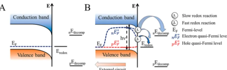
The band diagram of a p-type SC electrode (category B, common case for perovskites) is shown in
Figure 2. Underequilibrium conditions (without illumination), the Fermi level (E
F) of the SC and the redox potential of the electrolyte (E
redox) equalizes (Figure 2A). Under illumination, the quasi-Fermi level
of electrons deviates from the equilibrium value (Figure 2B). In the case of a slow redox reaction the surface concentration of electrons, and thus the quasi-Fermi levels are only slightly a
ffected. In this situation, both the cathodic corrosion and the redox reaction can occur simultaneously. Therefore, stability can only be achieved if the corrosion kinetics is slow (scenario 1). If the redox reaction is fast, however, it can consume the surface electrons to such an extent, that the quasi-Fermi level drops below the electrochemical potential necessary to induce cathodic corrosion (scenario 2).
In realistic situations, perovskite surfaces are not perfectly
flat on the atomic scale and contain various surface structures (e.g., grain boundaries, dislocations, terraces, and valleys).
37Such structural features are pronounced in nanostructured materials.
As the coordination of the atoms occupying these surface imperfections is lower, compared to the ones situated in the bulk, they become thermodynamically more susceptible to corrosion. These sites can be the initiators of the corrosion processes, which proceed in an accelerated fashion as the surface becomes more defective in the process. It is di
fficult to predict the exact corrosion potential of these sites, as it requires the complete understanding of the corrosion mechanism. Fur- thermore, these states can also act as recombination centers, promote dark reactions, or even cause Fermi-level pinning.
35Finally, the species present in the electrolyte can coordinate to these surface atoms weakening their back-bonds to the bulk and ultimately changing their corrosion potential.
38At the same time, nanostructured perovskites can also o
ffer bene
ficial properties that increase e
fficiency such as (i) short or directional charge carrier collection, (ii) tunable light distribution, (iii) quantum size e
ffects, and (iv) increased surface area.
39,402.2. Kinetics of Photocorrosion.
Di
fferent kinetic models
were developed to describe the mechanism of photocorrosion
and to evaluate the photostability of SCs.
41These models
exclusively focus on hole-induced decomposition (anodic
decomposition) and also take into account the charge carrier
generation and recombination (surface or bulk) processes. As
multiple participating species
42,43and interdependent steps
44can be involved in the overall reaction scheme, it often becomes
complex. Models rely on the description of the stepwise breaking
of the back-bonds of surface atoms (following charge carrier
generation). In the initial step, charge carriers generated in the
bulk are captured by these back-bonds. In a subsequent chemical
step, a component of the electrolyte stabilizes the radical-like
intermediate. The capture of a second charge carrier results in
Figure 1.Photocorrosion stability of SCs based on the position of the decomposition potentials relative to the band edge energies. (A) Stable against photocorrosion, (B) stable against anodic but susceptible to cathodic corrosion, (C) stable against cathodic but sensitive to anodic corrosion, and (D) sensitive toward both cathodic and anodic corrosion. Adapted from ref 33 with permission from Elsevier, copyright 1977. nE and pE stands for negative and positive charge induced decomposition process, respectively.the cleavage of the back bonds of the surface atoms, resulting in decomposition. Some sophisticated models consider these intermediates to be mobile on the surface.
42,43These elaborate models have important implications for perovskites, where light irradiation,
45−47applied electrical bias,
48−50or heat
51induce halide ion migration even within the perovskite lattice. Further complications arise when solution chemistry considerations (e.g., complexation, solution phase equilibria, multiple charge carrier redox processes) are taken into account.
43,52−55A detailed discussion of the different steps is given in the
SI.Although these studies were exclusively conducted on single crystal surfaces, the profound effect of surface imperfections on the corrosion rate was realized early on.
52,56,57The stabilization effect of redox couples can also be included in kinetic models, as either competing reactions for surface charge carriers or reactants that regenerate the partially broken surface bonds. Generally, the stabilization e
fficiency of a given redox pair is light intensity dependent.
44,58,59As the light intensity increases, the branching ratio between photocorrosion and the redox reaction shifts in favor of the decomposition process. In comparison, the stabilization e
fficiency of redox couples in the case of layered 2D materials was independent from the light intensity.
56This behavior was explained by (i) the reversibility of the
first charge carrier capture step and (ii) the fact that orbitals involved in driving the redox reaction, were not involved in bond formation.
34Similar enhanced stability was found for 2D perovskites compared to their 3D counterparts.
60Importantly, redox couples cannot be used (unless as mediators) in solar chemical or fuel production scenarios, as their presence will also suppress the desired reaction. In these situations, the kinetics (i.e., the branching ratio) will determine the degree of suppression. Therefore, the
“holy grail”would be to drive an industrially relevant redox reaction that simulta- neously is able to suppress photocorrosion. The thermodynamic criteria toward this reaction (i.e., redox potential) is ultimately limited by (i) the band positions, (ii) the corrosion potentials, and (iii) the bandgap of the perovskite.
61At this point, it is important to distinguish between photo(electro)catalytic or photo(electro)synthetic processes.
2,62Light-driven reactions that are thermodynamically
“downhill”(Δ
G< 0) can be termed photo(electro)catalytic, while thermodynamically
“uphill
”(
ΔG< 0) reactions are considered photo(electro)synthetic pro- cesses. In the case of photo(electro)catalytic systems, no net energy is stored in the formation of chemical bonds, the role of light is only to accelerate the otherwise sluggish reaction.
3. SPECIFICS OF PEROVSKITE PHOTOCORROSION
Perovskites are nonconventional intrinsic semiconductors.
Through the introduction of cation vacancies (lead and methylammonium) p-type behavior can be achieved, while
from the presence of anion vacancies (iodide), n-type behavior can be achieved.
63These defect sites can also be formed at the charge extraction layer/perovskite interfaces during the operation of solar energy conversion devices, pointing toward the active ion conducting nature of these materials.
64The anion in the perovskite lattice a
ffects the activation energy of ion migration, because of the di
fference in the Pb
−X bond strength and the vacancy density (which are the active participants in ion migration).
65For example, halide ion migration is more pronounced in MAPbI
3compared to MAPbBr
3. Interestingly, the migration of MA
+is also faster as a result of the expanded lattice of MAPbI
3.
65While these mobile ions in the
“soft”perovskite lattice are the main reasons behind the instability, they also allow the synthesis of perovskites with defect-free bulk structure using solution phase processes.
9Furthermore, these mobile ions are found to be the key reason for the self-healing properties of perovskites.
66The ambipolar charge carrier transport (with charge carrier di
ffusion length in the micrometer range) allows e
fficient electron or hole extraction from the bulk.
Therefore, both oxidation and reduction reactions can be driven on perovskite surfaces, especially when appropriate charge extraction interfaces are used.
673.1. Corrosion of Perovskite Photocatalysts.
To enable e
fficient PC or photosynthetic reactions, photogenerated charge carriers must be e
fficiently transported to catalytic sites where they must live long enough (without recombining) to be consumed in the catalytic reactions. Consequently, the long charge carrier di
ffusion length
5,6and lifetime
68coupled with the suppressed surface recombination
69of perovskites sparked an interest in their possible PC application. Furthermore, by incorporation of di
fferent anions into the perovskite structure, the band edge position can be tailored, to activate (oxidize or reduce) di
fferent organic substrates. This allows
fine-tuning of reaction mechanisms.
70,71The stability of perovskite-based PCs has been exclusively assessed through monitoring the product output and occasionally performing postrun measurements (X- ray diffraction (XRD), energy-dispersive X-ray microanalysis (EDX), X-ray photoelectron spectroscopy (XPS)).
3.1.1. CO2Reduction.
In PC CO
2reduction, mild polarity solvents such as ethyl-acetate
72−78or acetonitrile
75−77have been used as the media to ensure the stability of the perovskites.
A further advantage is that CO
2is highly soluble in these solvents (240 mM in ethyl acetate
72and 270 mM in acetonitrile
79). Interestingly, small quantities of water (<0.3%
v/v) was also added as a proton source and hole scavenger, without seemingly compromising the stability. The other half reaction in such PC systems is oxygen evolution from the added water.
72This aspect is often overlooked, although both water and oxygen can compromise the stability of perovskites.
Figure 2.(A) p-type SC electrode in the dark in contact with an electrolyte with a redox active species (Eredox) present, showing a depletion layer with arbitrary depth. (B) p-type SC electrode under illumination and in contact with an electrolyte with a redox active species, where the redox reaction is (1) slow and (2) fast. Adapted from ref35with permission from Royal Society of Chemistry.
Interestingly, the catalytic performance was relatively stable for hours.
72−78PC CO
2reduction was boosted by tailoring the shape of CsPbBr
3quantum dots. Through the introduction of thermodynamically less favored facets, enhanced CO and CH
4generation was detected. After PC experiments, the facet distribution was altered, yet the catalytic output remained stable.
73Fe(II) incorporation into CsPbBr
3was also performed to control the product distribution, but most of the Fe(II) leached out from the perovskite structure during the experi- ment.
74In the case of a MAPbI
3/Fe-based metal−organic framework (MOF), the hybrid material was more stable than the MOF itself.
A heterojunction of g-C
3N
4and CsPbBr
3nanocubes (NCs) was prepared to enhance the e
fficiency of charge separation.
Poor recyclability was observed when the hybrid PCs were prepared via simple physical mixing.
76When the CsPbBr
3NCs were anchored on amino functionalized g-C
3N
4through N
−Br bonds, better adhesion and recyclability were achieved.
77Similar grafting strategies were employed in the case of graphene-oxide/
CsPbBr
3NC
72and MXene/CsPbBr
3.
78A common feature of these studies is the slight decomposition of the ethyl acetate solvent or the ligand shell, which might form CO or CH
4during the PC reaction.
74,76,77While considered
“insigni
ficant
”in the studies, the resulting reactive reaction products can be either participants in the CO2R reaction (like the scavengers in water splitting
80) or detected as reaction products (e.g., CO and CH
4).
76The contribution of these unintended side reactions shall be quanti
fied. Furthermore, there are no experiments on the formation of liquid phase products. Currently isotope labeling studies are only carried out in a small fraction of the studies.
75−77Such protocols for both reduction (C
13O
2)
81and oxidation (H
2O
18)
82reactions are well-established. Further- more, the PC CO
2R mechanism on perovskite NCs is still unknown, and simply observing steady product generation is not a su
fficient indicator of stability.
3.1.2. PC Reactions in Organic Synthesis.
A perovskite- friendly environment has to be ensured during PC organic syntheses as well. Di
fferent co-reactants and various inter- mediate products can all compromise the stability of the active material.
71,83Highly nonpolar solvents have to be used (e.g., dichloromethane (DCM), hexane, toluene) that are rigorously purified from water and stabilizing agents.
70Interestingly, upon prolonged illumination (>24 h), the decomposition of DCM can yield chloride ions, which also participate in halide ion exchange
with the perovskite.
71,84Even easier halide ion exchange occurs using the halide salt of organic reactants.
71This can change the band edges of perovskite NCs during the PC reaction
in situ,opening new reaction pathways.
71Acid binding on perovskite surfaces can passivate surface defects that participate as active sites in the organic reaction.
85The C−C bond formation between tertiary amines and aldehydes is dependent on the acidity of compounds in the reaction mixture.
71Furthermore, smaller sized perovskite NCs had higher initial reaction rate (due to the increased surface area) but their catalytic activity diminished quickly.
71These alterations can be monitored following the shift in the photoluminescence peak, the UV
−vis absorbance onset, and the re
flections on the XRD patterns.
Various perovskite-based heterojunctions (both type II and Z- scheme) were employed for the photooxidation of benzyl alcohol to benzaldehyde.
83,86,87In the type II case, the perovskite acts as a sensitizer that injects photoexcited electrons to the CB of TiO
2(Figure 3A).
83,86These electrons react with molecular oxygen and form reactive superoxide radicals. The holes, remaining on the VB of perovskite, oxidize benzyl alcohol to carbocations. These react in a subsequent step with the superoxide radical, forming initially benzyl aldehyde and ultimately benzoic acid. In these PC reactions, only bromide- based (or chloride) perovskites are viable as the iodide-based counterparts are sensitive to the formed superoxide radical (eq
3). The superoxide radical can deprotonate the organic cation inthe perovskite lattice and oxidize the iodide in the lattice forming iodine (which can be released into the solution phase).
Importantly, this reaction also forms the basis of the light and oxygen induced degradation of perovskite solar cells.
884CH NH PbI O 4CH NH 4PbI
2I 2H O
3 3 3 2
deprotonation
3 2 2
2 2
+ ⎯⎯⎯⎯⎯⎯⎯⎯⎯⎯⎯⎯⎯→ +
+ +
•−
(3)
At its current state, all perovskite photocatalysts show poor recyclability; an example is shown in
Figure 3B.83,86The formation of the polar reaction product (benzaldehyde) can also degrade the catalysts, as shown in the case of FAPbBr
3.
83CsPbBr
3recycling experiments showed fading after 4 h, while the benzyl alcohol conversion decreased from 21% to 13%. In this case, the activity decrease was attributed to the loss of catalytically active sites.
86A Z-scheme heterojunction was formed in the case of
Bi
2WO
6/FAPbBr
3.
87Upon photoexcitation and subsequent
vertical charge separation, the electrons in the perovskite CB
Figure 3.(A) Illustration of the mechanism of photocatalytic benzyl alcohol oxidation process over TiO2/FAPbBr3heterojunction. (B) Recyclability of FAPbBr3and 15% FAPbBr3/TiO2in the photocatalytic oxidation of benzyl alcohol. Reproduced with permission from ref83. Copyright 2018 American Chemical Society.drive CO
2reduction to CO, while the holes in the VB of Bi
2WO
6facilitate direct benzyl alcohol oxidation, skipping the super- oxide formation step. The product evolution rates did not match the expected 1:1 stoichiometry, and superoxide formation from O
2was also shown.
87Furthermore, the pristine FAPbBr
3showed signs of degradation, yielding CO, which calls for further studies. Perovskite PCs with varying amount of iodide vacancies were also evaluated in the PC degradation of organic compounds, and the bene
ficial role of iodide vacancies via the increased production of radical O
2•−species was claimed.
89Surface termination can also play a role in the PC performance.
90When MAPbI
3was used for the PC conversion of 1,3-dihydroxyacetone to butyl lactate, MAI and PbI
2terminated surfaces were synthesized. The MAI terminated surface corroded rapidly to expose Pb(II) sites, which are photocatalytically active in the reaction. As expected, the catalytic activity initially increased but soon diminished as MAPbI
3was converted to PbI
2.
90The importance of surface characteristics was further highlighted when poly(3,4-ethyl- enedioxythiophene) (PEDOT) was deposited on the surface of CsPbBr
xI
3−xNCs.
91,92When the oleic acid in the shell was replaced with methyl acetate, faster PEDOT deposition was achieved, due to the increased number of surface defects and the shorter ligand shell. The importance of the ligand shell in PC reactions was further demonstrated when the reduction of ferrocenium
+(Fc
+) was only observed when the oleic acid/oleyl
amine was exchanged to didodecyldimethylammonium bromide (in the case, the spontaneous reduction of Fc
+occurred).
933.1.3. Hydrogen Evolution from Hydrogen Halide Sol- utions.
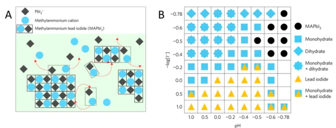
When MAPbX
3interacts with water, monohydrate (eq
4) and dihydrate (eq 5) phases are formed.94This is followed by the decomposition of the perovskite lattice, ultimately yielding insoluble PbX
2.
4CH NH PbI3 3 3+4H O2 F4 CH NH PbI H O[ 3 3 3· 2 ] (4)
4 CH NH PbI H O (CH NH ) PbI 2H O 3PbI 2H O
3 3 3 2 3 3 4 6 2 2
2
F
[ · ] · +
+ (5)
These chemical corrosion steps are the basis of the moisture sensitivity of perovskite-based devices. In aqueous media, in the presence of X
−, di
fferent soluble plumbate complexes form (mainly [PbX
3]
−and [PbX
4]
2−) from the water-insoluble PbX
2. In concentrated aqueous hydrogen halide solutions, these plumbate complexes form MAPbX
3, rather than the corrosion products (i.e., PbX
2or the hydrated species). This dynamic equilibrium (illustrated in
Figure 4A) between the corrosion(dissolution) and the reformation restructures the surface of the perovskite particles.
95The precipitation of the perovskite occurs in a narrow pH and [X
−] window (Figure 4B). The favorable band positions of perovskites (see also
Figure 9) make thesepseudostable systems capable of driving PC hydrogen evolution reaction (HER), which is accompanied by the respective halide oxidation reaction (a thermodynamically downhill gross
Figure 4.(A) Illustration of the dynamic equilibrium between solid MAPbI3and a saturated HI solution. (B) Effect of pH and I−content on the chemical makeup of the precipitate formed during the equilibrium process. Reproduced from ref95with permission from Springer Nature.Figure 5.(A) Illustration of theflow of charge carriers in a MAPbI3+ Pt/TiO2system during photocatalytic hydrogen evolution. (B) Proposed reaction scheme, where the TiO2/Pt surface acts as a temporary host for the deposition of MAPbI3nanocrystals, where the charge transfer chain is established. (C) Rate of H2evolution of pure MAPbI3, Pt decorated MAPbI3, TiO2−Pt/MAPbI3(Pt on perovskite), and Pt/TiO2−MAPbI3(Pt on TiO2) photocatalysts with illumination wavelengthsλ> 420 nm. Reproduced with permission from ref98. Copyright 2018 American Chemical Society.
Table1.SummaryofthePhotoelectrochemicalPerformanceofUnprotectedPerovskitePhotoelectrodes photoelectrodereactionelectrolyteperformancePEC stabilitylightsourcecommentref MAPbI3BQreduction0.1MBu4NPF6DCM−5.0mAcm−2(−0.4VvsFc/ Fc+)50%at 22h100mWcm−2 AM1.5G30μmlayer112 MAPbI3/PbI2(2.5%)BQreduction0.1MBu4NPF6DCM−7.0mAcm−2(−0.4VvsFc/ Fc+)unknown100mWcm−2 AM1.5G0−15%excessPbI2123 (MA)2CdCl4BQreduction0.1MBu4NPF6DCM−0.35mAcm−2(−0.7VvsFc/ Fc+)600h100mWcm−2 AM1.5GEBG=350nm124 MASnBrxI3−xBQreduction0.1MBu4NPF6DCM−1.0mAcm−2forMASnI3 (−0.7VvsFc/Fc+)50%at 40min100mWcm−2 AM1.5Ghalidecompositionoptimization116 CNT/CsPbBrxI3−xNCsBQreduction0.1MBu4NPF6DCM−0.5mAcm−2(−0.4VvsFc/ Fc+)a150mWcm−2 AM1.5GHalidecomposition,carbonnanotube(CNT)and perovskitethicknessoptimization117 MAPbI3none0.1MBu4NPF6DCM0.50μAcm−2(unknown)a100mWcm−2 AM1.5Gpositivecurrentflow,initialrapidcurrentdecay102 MAPbI3/CoPnone0.1MBu4NPF6DCM2.00μAcm−2(unknown)a100mWcm−2 AM1.5Gpositivecurrentflow,initialrapidcurrentdecay102 CsPbClxBr3−xNCsnone0.1MBu4NPF6ethyl acetate−4.4μAcm−2(unknown)a200mWcm−2 AM1.5G125 CsPbBr3NCsnone0.1MBu4NPF6ethyl acetate0.1mAcm−2(unknown)a300WXelamp (≥420nm)positivecurrentflow126 CsPbBr3NCs/MOF (UiO-66(NH2))none0.1MBu4NPF6ethyl acetate0.4mAcm−2(unknown)a300WXelamp (≥420nm)positivecurrentflow126 CsPbBr3nanocubesnone0.1MBu4NPF6ethyl acetate−0.18mAcm−2(−0.4VvsAg/ AgCl)a150mWcm−2 AM1.5GchangeinPLandXRDreflectionintensity73 CsPbBr3hexapodsnone0.1MBu4NPF6ethyl acetate−0.10mAcm−2a150mWcm−2 AM1.5GchangeinPLandXRDreflectionintensity73 CsPbBr3nanocubesnone0.1MBu4NPF6ethyl acetate−0.05mAcm−2a150mWcm−2 AM1.5GchangeinPLandXRDreflectionintensity73 CsPbBr3NCsnone0.1MBu4NPF6DCM−30μAcm−2(−0.4VvsAg/ AgCl)a150mWcm−2 (≥420nm)insituchemicaldepositionofMO2materialsbythe hydrolysisofprecursors118 CsPbBr3NCs/TiO2none0.1MBu4NPF6DCM−40μAcm−2a150mWcm−2 (≥420nm)insituchemicaldepositionofMO2materialsbythe hydrolysisofprecursors118 CsPbBr3−xClxNCs/SnO2none0.1MBu4NPF6DCM−60μAcm−2a150mWcm−2 (≥420nm)insituchemicaldepositionofMO2materialsbythe hydrolysisofprecursors118 CsPbBr3NCs/SiO2none0.1MBu4NPF6DCM−15μAcm−2a150mWcm−2 (≥420nm)insituchemicaldepositionofMO2materialsbythe hydrolysisofprecursors118 MAPbBr3CO2reduction0.1MBu4NPF6propylene carbonate−3μAcm−2(−0.6VvsAg wire)a100mWcm−2 AM1.5Gunstablecurrentresponse119 GO/MAPbBr3CO2reduction0.1MBu4NPF6propylene carbonate−5μAcm−2a100mWcm−2 AM1.5Gunstablecurrentresponse119 CsPbBr3NCsCO2reduction0.1MBu4NPF6ethyl acetate−38.0μAcm−2(−0.4VvsAg/ AgCl)a150mWcm−2 AM1.5GEDXrevealsFeisleachedout74 Fe:CsPbBr3NCs(25at %)CO2reduction0.1MBu4NPF6ethyl acetate−120.0μAcm−2a150mWcm−2 AM1.5GEDXrevealsFeisleachedout74 g-C3N4/CsPbBr3NCsCO2reduction0.1MBu4NPF6 acetonitrile−0.35μAcm−2(0VvsAg/ AgCl)a300WXelamp (≥420nm)77 CsPbBr3NCsCO2reduction0.1MBu4NPF6ethyl acetate−40μAcm−2(−0.4VvsAg/ AgCl)a150mWcm−2 AM1.5G72 GO/CsPbBr3NCsCO2reduction0.1MBu4NPF6ethyl acetate−50μAcm−2a150mWcm−2 AM1.5G72
Table1.continued photoelectrodereactionelectrolyteperformancePEC stabilitylightsourcecommentref CsPbBr3NCCO2reduction0.05MBu4NPF6ethyl acetate−20μAcm−2(−0.2VvsAg/ AgCl)a150mWcm−2 AM1.5G120 CsPbBr3NC/a-TiO2CO2reduction0.05MBu4NPF6ethyl acetate−200μAcm−2a150mWcm−2 AM1.5G120 CsPbBr3/Cs4PbBr6CO2reductionH2Owithoutadded electrolyte−1.0μAcm−2(−0.4VvsAg/ AgCl)a100mWcm−2 AM1.5Gperovskitesuspensionwasmeasured127 2%Co:CsPbBr3/Cs4PbBr6CO2reductionH2Owithoutadded electrolyte−3.0μAcm−2a100mWcm−2 AM1.5Gperovskitesuspensionwasmeasured127 c-TiO2/MAPbI3iodideoxidationMAPbI3-saturatedaqueous HI(57%)1.0mAcm−2(0.14VvsAg/ AgCl)8h150mWcm−2 AM1.5G106 c-TiO2/TiO2nanorod array/MAPbI3iodideoxidationMAPbI3-saturatedaqueous HI(57%)2.0mAcm−28h150mWcm−2 AM1.5G106 MAPbI3H2evolutionaqueousHI(57%)with H3PO20.75μA(unknown)a300WXelamp (≥420nm)positivecurrentflow101 MAPbI3/Ni3CH2evolutionaqueousHI(57%)with H3PO21.50μA(unknown)a300WXelamp (≥420nm)positivecurrentflow101 MAPbI3/black-PH2evolutionMAPbI3-saturatedaqueous HIsolution110μA(unknown)a300mWXelamp (≥420nm)positivecurrentflow100 MAPbBrxI3−xH2evolutionmixedaqueousHBr/HI withH3PO21.75μAcm−2for MAPbBr0.45I2.55(unknown)a300WXelamp (≥420nm)positivecurrentflow97 CsPbBr3NCswaterreduction0.1MNa2SO4,water pH=6.8−3μAcm−2(−0.1VvsNHE)6h405nmLEDinitialcurrentdecay,withincreasingdarkcurrent121 CsPbBr3NCs/TiO2waterreduction0.1MNa2SO4,water pH=6.8−5μAcm−26h405nmLEDinitialcurrentdecay,withincreasingdarkcurrent121 TiO2/CsPbBr32-mercapto- benzothiazole oxidation 0.1MBu4NPF6DCM0.15mAcm−2(−1.0VvsNHE)a100mWcm−2 AM1.5Gn-typebehavior,slightabsorbancechangeafterPEC128 a Notavailable.
reaction). As HER progresses, X
−is simultaneously depleted from the solution and the addition of selective reducing agents (such as H
3PO
2) becomes necessary to reform the perovskite phase.
To enhance the performance (activity, selectivity, and stability) of perovskite photocatalysts in HX splitting reactions, di
fferent strategies were employed: (i) preparing mixed halide compositions,
96,97(ii) anchoring various HER catalysts (e.g., Pt,
95,98,99black-P,
100rGO,
99Ni
3C,
101CoP,
102Mo
2S
103), or (iii) grafting additional hole extraction materials (e.g., PE- DOT:PSS,
104carbonized polymer dots
105) on the perovskite surface. In the case of TiO
2/MAPbI
3hybrids, a distinct di
fference was found in both e
fficiency and stability between loading the Pt on the stable TiO
2or on the dynamically changing MAPbI
3surface.
98It was proposed that when the Pt is deposited on MAPbI
3and then combined with TiO
2in a subsequent step, the dissolution of the MAPbI
3surface removes the Pt catalyst.
This was not the case when the Pt catalyst was predeposited on the TiO
2and then added to the MAPbI
3containing solution (Figure 5A,B). This difference was also observed in the H
2evolution rate (Figure 5C). Interestingly, no such behavior was observed in other cases, where Pt was directly deposited on MAPbI
3.
95,99−103When one adapts this strategy to PEC applications,
106care must be exercised as the free-standing perovskite
films can be slowly dissolved into the concentrated HI solution.
983.2. Corrosion of Perovskite Photoelectrodes.