In: Sensors and Actuators B: Chemical, 297: 126649 (2019) 10.1016/j.snb.2019.126649
Manuscript as accepted.
This work is licensed under the Creative Commons Attribution-NonCommercial- NoDerivatives 4.0 International License (CC BY-NC-ND 4.0).
A silicon-based spiky probe providing improved cell accessibility during in vitro slice recordings
Domokos Meszéna1, 2, Bálint Péter Kerekes1, 2, Ildikó Pál1, Gábor Orbán3, Richárd Fiáth1, 2, Tobias Holzhammer4, Patrick Ruther4, 5, István Ulbert1, 2* and Gergely Márton1, 2, 3
1 Institute of Cognitive Neuroscience and Psychology, Research Centre for Natural Sciences, Hungarian Academy of Sciences, Budapest, H-1117, Hungary
2 Faculty of Information Technology and Bionics, Pázmány Péter Catholic University, Budapest, H-1083, Hungary
3 Óbuda University Doctoral School on Materials Sciences and Technologies, H-1034, Budapest, Hungary
4 Microsystem Materials Laboratory, Department of Microsystems Engineering (IMTEK), University of Freiburg, D-79110 Freiburg, Germany
5 BrainLinks-BrainTools Cluster of Excellence at the University of Freiburg, D-79110 Freiburg, Germany
*Correspondence:
István Ulbert
ulbert.istvan@ttk.mta.hu Phone: +36-1-382-6801 Fax: +36-1-382-6295
Institute of Cognitive Neuroscience and Psychology, Research Centre for Natural Sciences, Hungarian Academy of Sciences, Magyar tudósok körútja 2.
Budapest, H-1117
Abstract
Aims. In this study, we introduce an edge-type laminar silicon probe suitable for improved cell accessibility during in vitro brain slice recordings. With protruding contact sites, the spiky probe provides high signal yield and quality while approaching cells located deeper in the tissue.
Methods. The spiky probe comprises an angled shank carrying 32 protruding contact sites with three possible spacing of 25 µm, 50 µm and 100 µm. The angled shank makes the probe compatible with large microscope objectives used typically in two-photon imaging, in vitro.
Spiky probes were batch manufactured with high precision using the etching before grinding technology and bonded to a custom designed printed circuit board. A quantitative comparison of the performance was made against a commercially available surface probe. To investigate the long-term stability of contact sites, the spiky probe was repeatedly inserted in seven experiments (17 insertions, in total) using Wistar rat hippocampal slices, in vitro. Impedance magnitudes and phase angles were compared before and after the extensive usage.
Results. Single unit activities were recorded with higher neuronal yield and higher amplitudes compared to the surface probe. Impedances did not increase significantly after reusing the probe in multiple experiments. Furthermore, we were able to detect extracellular action potentials from the same single unit on multiple, adjacent contact sites. Finally, we separated the recorded single units into putative cell types based on their extracellular waveforms.
Conclusion and outlook. The spiky probes were proved to be optimal solutions to record extracellular spike waveforms, in vitro. The improved signal quality allowed us to distinguish between putative interneurons and principal cells. In future works, integrative experiments using these probes may provide multi-modal data for cellular electrophysiology resulting in a deeper understanding of single cell contributions to mass neural activity.
Keywords
Edge design,
Extracellular potentials,
Single unit activity,
In vitro recordings
Protruding contact sites
Abbreviations
MEA Multi-Electrode Array LFP Local Field Potential MUA Multiple Unit Activity SUA Single Unit Activity
SW Sharp Wave
AP Action Potential
EAP Extracellular Action Potential aCSF Artificial Cerebrospinal Fluid FPGA Field Programmable Gate Array PCA Principal Component Analysis PCB Printed Circuit Board
EBG Etching Before Grinding
PECVD Plasma Enhanced Chemical Vapour Deposition RIE Reactive Ion Etching
DRIE Deep Reactive Ion Etching
Introduction
Studying the physiological function of complex neural activity patterns involves various electrical and optical methods as well as computational tools with interdisciplinary approaches from different fields. Historically, extracellular potential recordings have been started using single wires [1], tetrodes [2], [3], and performed more recently via multi-channel silicon probes [4]–[7] or so-called polytrode [8] as well as polymer-based soft probes [9]–
[12]. Thanks to the rapid development of the silicon-based batch manufacturing technologies, multi-channel probes became available in a wide variety of shapes, layouts with submicron reproducibility and with only low restrictions regarding their physical configurations [13]–
[15]. In addition, the channel counts placed on a single shank increased exponentially in the past few years [16]–[23]. Besides single- or multi-shank probes, Multi-Electrode Arrays (MEAs) were also developed for in vitro cell culture and brain slice applications [13], [24].
These MEAs are made of using complementary metal-oxide-semiconductor (CMOS) technologies enabling high-density contact site arrangement [25], [26]. While such devices gained significant impact on the discovery of neural circuitry and dynamics, many questions remain mostly unanswered about the interpretation of the recorded signals [27], [28]. It is critical to demonstrate the recording capabilities and limits of a certain probe to understand how neuronal signals are transformed and transmitted during the acquisition [29], [30].
In this study, we focus on the in vitro brain slice electrophysiology considering recordings of extracellular, multi-channel laminar probes. Cutting the brain into slices has allowed access to neurons located deeper in the brain. The method can be used for imaging or recording neural activities that are otherwise difficult to reach and detect in vivo. Similarly to in vivo conditions, it is possible to observe population activities in brain slices, such as sharp waves (SW) or other oscillations inherent in different states of the brain [13]. These population
activities are mainly in the local field potential (LFP) band (0.5 - 100 Hz), which is the low- frequency part of extracellular potentials. As well as in vitro single- and multi-unit activities (SUA and MUA) can be found by high-pass filtering the extracellular potentials (0.5- 5 kHz).
Furthermore, an additional advantage of in vitro brain slice recordings is the capability for combining different modalities, which would be again, challenging or not feasible in vivo.
Such possible combinations are among others the simultaneous intracellular pipettes, local delivery of drugs, or two-photon laser scanning microscopy [31], [32].
Considering extracellular recordings, it is well known, that electrical signals in the neural tissue are detectable even at further distances from their source, the phenomenon is called volume conduction [33], [34]. However, several complications may emerge from the volume conductive property of the neural tissue and from the summation of different current sources and sinks over distance [35]. These drawbacks make the interpretation of the extracellular potentials extremely challenging. Besides theoretical considerations, measurement related technical challenges also play an important role in achieving high quality results. The closer an extracellular device is positioned to the putative neuronal source, the better recording quality is achievable. An unsuitably designed layout of contact sites would prevent the detection of electrical activity of a further neural source which would have been otherwise detectable with an optimal technique. Sufficiently large signal amplitudes are needed to feed in the theoretical calculations in order to achieve correct results. In the neural tissue, one has to be closer than 100-150 µm from a certain neuron in order to detect its firing activity [36], [37]. Previous studies have shown that small contact site area and sufficiently low impedance are also crucial to detect well-isolated extracellular action potentials (EAPs) over the background noise [18]. However, the area of the contact site and its impedance are inversely proportional to each other [38]. In addition to this, a well-designed electrode-tissue interface is also needed to access recorded cells without significantly damaging them, and to detect as
many as possible active cells in the close vicinity of the probe [39], [40]. In brain slice extracellular electrophysiology (such as MEA systems or surface probes), this requirement is particularly important, since the surface of the slice is considered to be a dead-cell layer due to cut-off dendrites and cell bodies [41], [42]. This electrically passive dead-cell layer frequently attenuates SUAs originated from other, physiologically more active cells located deeper in the tissue [43], [44].
The spiky probe demonstrated in this study allows for approaching these deeper cells, and enables sufficient spatial sampling of their EAPs. Thanks to its arrowhead-like, protruding contact sites, the probe can slightly penetrate into the deeper tissue, passing through the surface dead-cell layer. Due to this arrangement, we report that our probes are able to provide a higher single unit yield as well as spikes with higher amplitudes than other, in vitro laminar surface design attempts [45], [46].
In the following sections, manufacturing processes and packaging methods will be described.
Next we show the results of impedance measurements. In addition, the recording performance of the probes will be demonstrated using in vitro hippocampal slices. With a quantitative comparison, we show the improvements of our spiky probe compared to a commercially available in vitro surface probe. A preliminary result of how the spiky probe can be combined with two-photon imaging modalities will be also presented. Finally we report how the spiky probe is able to capture and oversample the single unit activities on multiple contact sites and how the recorded EAPs can be analysed to distinguish between putative neuronal cell types.
Materials and methods
Surface materials and fabrication process
The fabrication process of the silicon (Si) based spiky probes is schematically summarized in Figure 1. The fabrication process applies 4-inch, single-side polished Si wafers, insulated using a 1-µm-thick, stress-compensated multi-layer stack of silicon oxide (SiOx) and silicon nitride (SixNy) deposited using plasma enhanced chemical vapor deposition (PECVD) (step a).
The interconnect and contact pad metallization (line and space of 1.5 and 1.5 µm, respectively) was realised using lift-off patterning of an evaporated layer stack of titanium (Ti, 30 nm), gold (Au, 250 nm) and Ti (30 nm) (step b). The Ti layers serve as adhesion promoters between the insulation and the subsequently deposited passivation layers, and the Au film. We used the image reversal photoresist AZ 5214E (Merck KGaA, Darmstadt, Germany). Following the lift-off process, the metallization is passivated using another stress- compensated 1.5-µm-thick PECVD SiOx-SixNy layer stack (step c). This is followed by opening the passivation layer to access the probe metallization at the position of the contact sites and contact pads using photolithography (AZ4533, 3.3 µm, Merck KGaA) and reactive ion etching (RIE) (step d). Subsequently, the contact site metallization is deposited using a dual-layer lift-off resist (LOR5A, MicroChem Corp., Westborough, MA, USA and AZ1518, 1.8 µm, Merck KGaA) and sputter deposition of Ti (30 nm), platinum (Pt, 150 nm), iridium (Ir, 100 nm) and iridium oxide (IrOx, 200 nm, reactively sputtered in an oxygen plasma) (step e) [47]. Next, the dielectric layers, i.e. SiOx-SixNy insulation and passivation layers, are patterned using photolithography (AZ9260, 10 µm, Merck KGaA) and RIE (step f). Then, the bulk silicon is etched (using the etching before grinding (EBG) technology [48]) to a depth that exceed the intended probe thickness by roughly 30 µm using deep reactive ion etching (DRIE) in an inductively coupled plasma (ICP Multiplex from STS, Newport, U.K.) etching
process which applies the Bosch process (step g) [49]. Finally, the Si wafer is thinned from the rear side using grinding and polishing as offered by DISCO Hi-TEC Europe GmbH, Kirchheim, Germany (step h). Probes are then manually picked from the grinding tape using tweezers, glued onto a custom designed printed circuit board (PCB) and wire bonded. The bond wires are finally encapsulated in a glop-top (EPO-TEK 353ND-T, Polytech PT GmbH, Germany) for electrical insulation.
Figure 1 – Fabrication of silicon-based spiky probes. (a) PECVD insulation layer, (b) sputter deposition of Ti/Au/Ti and patterning by lift-off using image reversal resist (c & d) deposition and RIE patterning of PECVD passivation layer, (e) deposition and lift-off patterning of Pt/Ir/IrOx metallization of contact sites using dual layer lift-off resist, (f) RIE patterning of dielectric layers, (g) DRIE of bulk silicon, and (h) rear side grinding of Si to intended probe thickness of 50 µm.
Brain slice preparation
Acute horizontal hippocampal slices were prepared from 14 Wistar rats (between 250-300g, gender balanced). We tested electrophysiological performances by using seven rats (with 17 insertions, in total) for the spiky probe and seven rats (with 9 insertions, in total) for a commercially available 24-channel, in vitro surface probe (modified U-type probe, Plexon Inc., TX, USA) [50], [51]. One additional Thy1-GCaMP transgenic mouse (#1, male, 30 g) was used for testing the spiky probe under combined imaging of two-photon microscopy.
Animals were bread and reared in the Research Centre of Natural Sciences, Hungarian Academy of Sciences. Animals were supplied with food and water ad libidum and were kept on a 12-12 hour light-dark cycle. All of the protocols followed the guidelines of the Hungarian Act of Animal Care and Experimentation (1998; XXVIII, section 243/1998.). The Animal Care and Experimentation Committee of the Hungarian Academy of Sciences, and the Animal Health and Food Control Station have approved our experimental design (license number: PEI/001/2290-11/2015). Efforts were made to minimize animal suffering and to reduce the number of animals used. Before the experiment, the animals were deeply anesthetized with isoflurane (min. 0.2 ml/100 g), quickly decapitated and their brains were immediately removed and dipped into cold (2–3 ˚C), oxygenated (95% O2, 5% CO2) cutting solution. The cutting solution contained the following composition (in mM): 250 Sucrose, 26 NaHCO3, 10 D-Glucose, 1 KCl, 1 CaCl2 and 10 MgCl2. 500 µm-thick horizontal slices were cut by a vibratome (VT1200s; Leica, Nussloch, Germany) from both hemispheres containing the whole hippocampal formation. Slices were kept in a standard artificial cerebrospinal fluid (aCSF) solution at room temperature (20–22 ˚C) for at least 1 h before use. The recordings were performed at 32-34 ˚C with a standard recording aCSF containing (in mM): 124 NaCl, 26 NaHCO3, 10 D-Glucose, 4 KCl, 2 CaCl2 and 2 MgCl2. In the recording chamber, a dual- perfusion system was used by perfusing both the top and the bottom surfaces of the slices
with relatively high perfusion speed (>10 ml/min) to provide better oxygenation, similar to in vivo conditions [41]. Under these conditions, sharp wave (SW) events and single units activities were reliably detected [51], [52]. After every recording session, the probes were withdrawn and to eliminate tissue residue, cleaned by immersing into 1% Tergazyme solution (Sigma-Aldrich, St. Louis, MO, USA) for at least 30 minutes followed by rinsing with distilled water.
Acquisition and analysis of the extracellularly recorded potentials
Extracellular recordings of the local field potentials (LFP), multiple unit activity (MUA) and single unit activity (SUA) were performed in hippocampus (CA1 and subiculum regions) and neocortex of the horizontal brain slices. For comparing the recording performance of the spiky probe, we used a commercially available 24-channel, in vitro laminar surface probe (modified U-type probe, Plexon Inc., TX, USA) [50], [51]. This is a metal probe carrying 24 Pt/Ir contact sites (with an inter-contact distance of 50 µm). Our in vitro set-up was built under a two-photon laser scanning microscopy system (Femtonics Ltd., Budapest, Hungary).
For electrical signal acquisition we used the INTAN RHD2000 FPGA-based system (InTan Technologies, Los Angeles, CA, USA). The acquisition system was connected to an external laptop via USB 2.0 connection. Wideband signals (0.1 Hz – 7.5 kHz) were recorded with 16- bit resolution, at a sampling rate of 20 kHz/channel. Data containing three-minute-long continuous recordings were saved to internal network storage for further analysis. Signals were pre-processed using custom-written MATLAB programs (The MathWorks, Natick, Massachusetts, USA), visualized firstly by the NeuroScan 4.5 Software package (Compumedics Neuroscan, Charlotte, North Carolina, USA). To extract the activity of single units from the recorded neural signals, automatic spike sorting was performed using the Kilosort software package [53], [54]. Manual supervision of the single-unit clusters detected
by Kilosort was done in Phy, an open-source neurophysiological data analysis package written in Python (source: https://github.com/kwikteam/phy). The selection of well-isolated single units was further aided by using two additional criteria [55]. First, the peak-to-peak amplitude of the mean spike waveform of neurons had to be larger than 50 µV. The peak-to- peak amplitude was defined as the absolute amplitude difference between the negative peak and the largest positive peak of the neuron’s mean spike waveform, calculated on the recording channel on which the spike waveform of the particular unit appeared with the largest amplitude. Second, selected single units had to have a clear refractory period, defined by a “violation rate” below 2%. The violation rate of a single unit (expressed in percentage) is the proportion of spikes in a particular cluster that are followed within 2 ms by other spikes belonging to the same cluster. Using these two criteria allowed us to exclude the majority of low quality units as well as to decrease the effect of subjective decisions of the operator during the manual curation of neuron clusters. To differentiate between neurons firing narrow and wide spikes (corresponding to putative interneurons and principal cells, respectively) we computed the trough-to-peak times of the mean spike waveforms [56]. Unsupervised hierarchical clustering (Ward’s method with Euclidean distance) was applied to separate the two types of neurons using the calculated spike duration as input feature [57].
Results
Probe structures and packaging
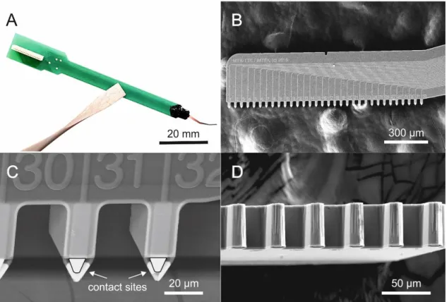
The spiky probe allows for performing extracellular multi-site recordings within an in vitro plate located under a water-immersive microscope objective, which has a focal length of 2 mm. Figure 2/A illustrates how the probe geometry fits in a typical measurement situation.
The optimally angled silicon shank of the device provides a relatively large freedom for positioning between the wall of the plate and the objective. The silicon shank carries 32 contact sites in a horizontal, laminar arrangement. The contact sites are located at the bottom edge of the shank. Furthermore, they are semi-circularly released from the bulk to form arrowhead-like or spiky shapes (See Figure 2/B for schematics and Figure 3/B-D for SEM pictures). Because of these spiky contact sites, the probe has the ability to penetrate into the brain slice, diving beneath the surface dead-cell layer. Moreover, its tips can even approach individually targeted cells if a precise image-guidance is applied during insertion (for details, please also see Figure 5/A-B later). The angled probe allows us to obtain combined optical information and simultaneously monitor the measured region with a two-photon laser scanning microscope system (Femtonics Ltd., Budapest, Hungary), which has a near-infrared bright-field camera mode and a two-photon fluorescent mode as well.
Figure 2 – Schematics of the experimental design, as well as packaging and bonding of spiky probe layouts. A: Positioning of the angled shank between in vitro plate and microscope objective in a typical experimental situation. The optimally angled shank provides relatively large freedom for positioning the device between the wall of the perfusion chamber and the objective. B: Three different versions of the device which differ from each other only in the inter-contact distance, i.e. the high-density version with 25 µm, followed by 50 µm of the medium-sized variant and 100 µm of the longest type.
Three different versions of the spiky probes were created, which only differ from each other in the spacing of the 32 contact sites. The inter-contact distances (center-to-center) of 25 µm, 50 µm and 100 µm were realized resulting result in total spans of 775 µm, 1550 µm and 3100 µm, respectively (see Figure 2/B, top). The shortest type is suitable for high-density recordings, while the longer types can cover more cortical layers and thus have a larger sampling area. The microfabricated part is glued onto and wire-bonded to a rigid printed
circuit board (PCB) specifically designed for this purpose. It provides interconnection to the external instrumentation. Detailed tests for the performance and stability of contact sites (presented in the following sections) were obtained mainly by using the high-density version (25 µm inter-contact distances). The dataset of spatially oversampled single units were collected with the same spiky probe version. The other two versions (namely the spiky probes with 50 µm and 100 µm inter-contact distances) were both totally functioning and were tested at least once. We included their impedance results but such detailed in vitro recordings presented for the high-density probe are still to be investigated, which go beyond the scope of the current study.
Figure 3 – Optical photograph and scanning electron microscopy (SEM) images of the spiky probe. A: Picture of a fully assembled device showing the main probe components from right to left: a single silicon shank (grey and red), glop top protecting the bond wire (black), the printed circuit board (PCB, green) and the Omnetics connector (white). B: SEM picture of the silicon shank showing the laminar arrangement of the 32 contact sites of the medium-sized spiky probe version (with inter-contact distance of 50 µm) and related wiring. C-D: SEM close-up views at two different orientations. Please note the arrowhead-shape, protruding contact sites.
Impedance measurement
Before in vitro experiments, electrochemical impedance spectroscopy was tested on each probe for diagnostic purposes. A built-in impedance checking protocol was used implemented by the INTAN RHD2000 acquisition system (InTan Technologies, Los Angeles, CA, USA).
The impedance magnitudes and phase angles of all contact sites on each probe were measured, at various frequencies ranging from 20 Hz up to 5 kHz. The impedance measurement was carried out in physiological saline solution against an Ag/AgCl reference electrode. It is well known that the impedance of a contact site is inversely proportional to its area [13]. In the case of the high-density spiky probe (with inter-contact distance of 25 µm), the electrode area (triangular) is 32 µm2, for the medium version (with inter-contact distance of 50 µm) is again 32 µm2, and for the biggest version (with inter-contact distance of 100 µm) is 50 µm2. For the surface probe (modified U-type probe, Plexon Inc., TX, USA) used in comparative tests, the area (circular) is 176.7 µm2.
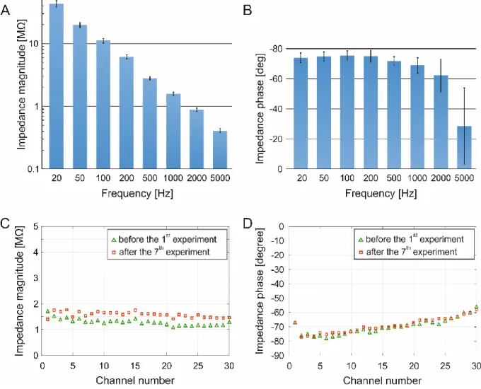
Figure 4/A &B shows the impedance spectroscopy of the high-density spiky probe (with inter- contact distance of 25 µm), alias the mean impedance magnitudes with corresponding standard deviation, at varying frequency levels (before the first in vitro experiment). Please note that the impedance magnitudes were monotonically decreasing from 20 Hz up to 5 kHz with a small standard deviation between contact sites. We highlight the particular frequency of 1 kHz, where this high-density spiky probe showed average impedance magnitude of 1.27
± 0.1 MΩ across all contact sites with an average phase angle of -70 ± 5º. The phase angles varied much less up to 2 kHz ranges for a given contact site, and they also varied minimally between sites (Figure 4/B). Furthermore, two faulty contact sites (6.25 % out of 32 contact sites) with impedance magnitudes higher than 3 MΩ at 1 kHz were found on this particular probe, they considered as open circuits and thus were excluded from further analysis.
We have tested the two different spiky probe versions as well, even if we did not performed more recordings using them in this study. We shortly report the impedance results at 1 kHz, where the average impedance magnitudes on the medium spiky probe (with inter-contact distance of 50 µm) were comparable with the high-density version (since they have equal sized electrode areas), namely 1.27 ± 0.3 MΩ, with averaged phase angle of -60 ± 4º, and two faulty contact sites were found (open circuits, 6.25% out of 32 contact sites). Lastly, for the longest probe (with inter-contact distance of 100 µm) the average impedance magnitude was 600 ± 20 kΩ, with average phase angle of -56 ± 5º, which were similar to the surface-type Plexon U-probe (magnitudes of 616 ± 160 kΩ and phase angles of -56 ± 7º). On the biggest spiky probe we found only one faulty site (short cut, 3.125% out of 32 contact sites). The ratio of faulty contact sites remained well below 10% for all three spiky probes. We hypothesised that these faulty contact sites appeared due to the soldering of Omnetics connectors to the PCB, which can be further improved in future work. Nonetheless, the exclusion of faulty sites did not significantly compromise the quality of recordings because of the dense spatial sampling capability.
We also wanted to test the robustness and reusability of spiky contact sites. Impedance changes of the high-density spiky probe (with the inter-contact distance of 25 µm) were investigated after an extensive usage (7 experiments with 17 separate insertions, in total) by repeating the impedance test after the last experiment. At this time, we compared the magnitudes and phases only at 1 kHz, since this frequency is widely used as a standard. Other experimental conditions remained unchanged. On Figure 4/C &D we show the impedance magnitude and phase changes measured at 1 kHz before and after the extensive usage. The average impedance magnitude of all contact sites was 1.27 ± 0.1 MΩ before the first experiment and was slightly increased after the last experiment to 1.5 ± 0.1 MΩ. However, such minor changes are still acceptable in the literature (e.g. NeuroNexus probes have
impedance magnitude values typically between 0.5-2 MΩ [8]). The impedance phase angles did not change significantly across this time period, starting with an initial average phase angle of -70 ± 5º which remained at around -69 ± 5º after extensive testing.
Figure 4 – Impedance magnitudes and phase angles. A-B: Impedance spectroscopy. Mean impedance magnitudes (A) and phase angles (B) with corresponding standard deviations at different frequencies ranging from 20 Hz to 5 kHz. Please note the monotonically decreasing magnitudes and phase angle values and the small standard deviations across channels. C-D:
Testing the stability and re-usability of spiky contact sites. Impedance magnitudes (C) of all contact sites (at 1 kHz) before the first experiment (green) and after seven experiments (17 insertions), in total (red). Please note the relatively small changes after an extensive probe usage. Phase angles (D) of all contact sites (at 1 kHz) remained practically the same after the extensive usage.
In vitro recording characteristics
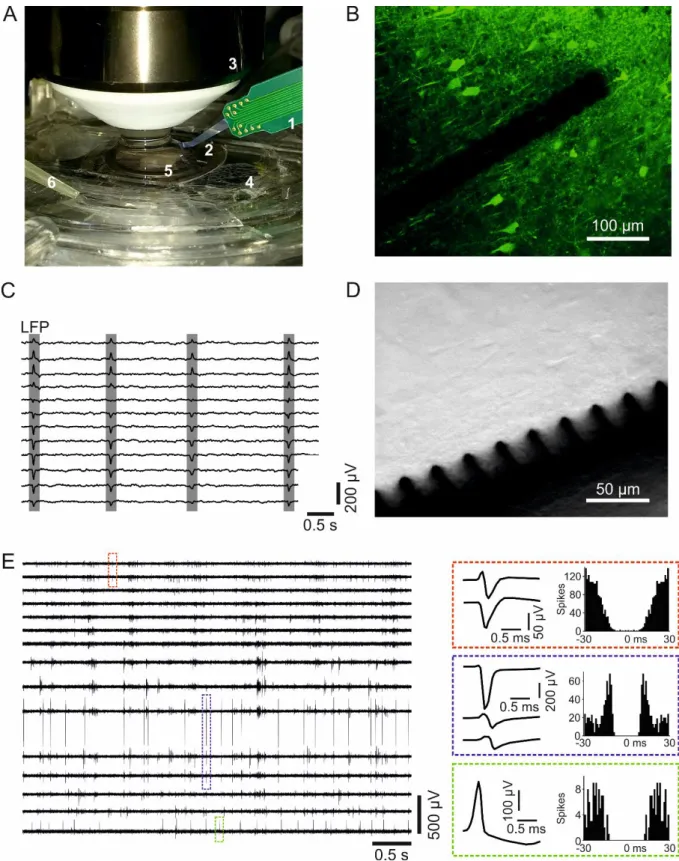
To validate the electrophysiological performance of the spiky probes, we have performed extracellular recordings in the hippocampus and neocortex regions of horizontal brain slices from Wistar rats. We show a typical experimental arrangement on Figure 5/A. Thanks to the optimal shank curvature and carefully chosen penetration angles, the probe easily fits into the gap between the perfusion chamber and the water-immersion objective of the two-photon laser scanning microscopy system (Figure 5/A-B). By using the near-infrared camera-mode of the microscope, precise image-guided positioning of the probe is achievable.
While inserting the spiky probe, it is important to check whether the protruding contact sites are horizontally placed before approaching the surface of the brain slice. The optimal insertion angle is 22˚ respect to the main axis of the main shank. Tilting can be easily checked before penetration under the water immersed objective by focusing onto the protruding contact sites. If the horizontal arrangement is achieved, the probe can be lowered and its spiky contact sites can be inserted into the brain slice without any further risk for fracture. If the horizontal arrangement is not achieved, the tilted probe should be retracted and repositioned.
As with any type of inserted device, it is not recommended to move in x-y direction once the probe was inserted into the slice. We have not experienced any fracture on the spiky probe while used as described above. We approached cells located in CA1 and subiculum regions of the hippocampus, as well as layer 2/3 cells in the neocortex. These deeper cells are located 70-80 µm beneath the brain slice surface, where – according to the literature – they mainly preserved physiological conditions [41], [42]. As with any in vitro recordings, neuronal activities depends on numerous factors, namely oxygenation, perfusion rate of the aCSF, chamber temperature, brain slice quality, or the number of nearby active neurons, which highly depends on the location [41]. In our experience, every single insertion yielded SUAs and MUAs at higher frequencies (between 0.5 kHz – 5 kHz) as well as low-frequency LFP
phenomena (from 0.5 Hz up to 100 Hz) with a sufficiently small amount of background noise.
Figure 5 shows the two typical working modes of the microscope system, the fluorescent two- photon imaging mode (Figure 5/B), and the basic camera mode (Figure 5/D). While the protruding contact sites are clearly visible in the camera mode, they are much less distinguishable from the dark silhouette of the main shank in the two-photon mode. It should be noted that pictures and extracellular recordings were not taken from the same insertion.
Figure 5/C shows examples of hippocampal sharp wave (SW; gray rectangles) activity recorded by twelve adjacent contact sites of the spiky probe. Here, the wideband signal was band-pass filtered for extracting the low frequencies (between 0.5 Hz – 40 Hz). On Figure 5/E, representative 5-second-long unit activity acquired by fifteen adjacent contact sites. To enhance the visibility of spikes, the recorded wideband data was band-pass filtered focusing on the higher frequencies (between 0.5 kHz – 5 kHz).
After validating the capability of signal acquisition, quantitative comparison was made against an in vitro laminar surface probe to prove the expected advantages of the spiky probe over a surface design [50], [51]. Neural yields (single unit counts per recording), average and maximal spike amplitudes, as well as noise levels were compared for both types of probes.
Firstly, we investigated differences in the noise levels by estimating the root mean square (RMS) noise level in aCSF. In case of the spiky probe, the RMS noise was 9.71 ± 2.12 µVrms
(0.1 – 7500 Hz; average ± standard deviation) measured on 32 contact sites of the high- density probe (with 25 µm inter-contact distance). While for the surface probe an average of 6.88 ± 0.58 µVrms was measured (0.1 – 7500 Hz) on 24 contact sites (with 50 µm inter-contact distance). The input-referred noise of the amplifier was 2.4 µVrms. In the spike band (500 – 5000 Hz), there was only a small difference in the RMS noise level between the two probes, namely 4.63 ± 0.51 µVrms for the spiky probe versus 3.93 ± 0.42 µVrms for the surface probe.
Placing the probes on a brain slice elevated the measured noise level by 10 - 20%.
Figure 5 – In vitro recording characteristics of the spiky probe. A: Photograph of the experimental set-up. Numbers represent the following parts: PCB (1), silicon shank (2), water immersion objective (3), dual-perfusion chamber (4), hippocampal slice and the holder grid (5), outlet of the aCSF (6). B: Example for visualizing of the high-density spiky probe (with 25 µm inter-contact distance) in two-photon imaging (Thy1-GCaMP transgenic mouse neocortex, please see the Methods section for details). C: Hippocampal sharp waves (SW;
gray rectangles) recorded recorded from the CA1 region of a Wistar rat shown on twelve channels from Wistar rat CA1 region. The wideband signal was filtered (0.5 – 40 Hz
bandpass) to extract the local field potential (LFP). D: Example for visualizing the spiky probe in bright-field camera mode (Wistar rat neocortex). Pictures and extracellular recordings were taken from different recording sessions. E: Representative 5-second-long unit activity recording acquired by fifteen adjacent contact sites of the probe. To enhance the visibility of spikes, the recorded wideband data was bandpass filtered between 500 and 5000 Hz. Colored dashed rectangles located on the traces mark a single spike of three sample single units. Mean spike waveforms and autocorrelograms (bin size, 1 ms) corresponding to these units are shown on the right.
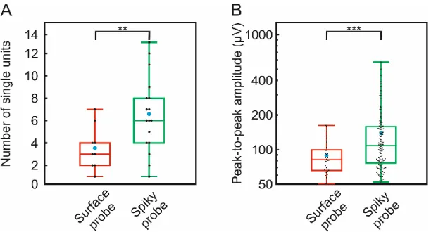
Figure 6 shows the distribution of the number of well-separated single unit clusters (Figure 6/A) and the distribution of the peak-to-peak amplitude of these waveforms (Figure 6/B) for both probes. The total number of well-separated neurons was 32 for the surface probe and 112 for the spiky probe. Since we had an unequal number of recordings from the two probes (17 positions for spiky probe, 9 positions for surface probe) we calculated more sophisticated unit yields per position. On the box plots, the middle line indicates the median, while the boxes correspond to the 25th and 75th percentile. Whiskers mark the minimum and maximum values. The average is depicted with blue dots. The average yield was 6.6 for spiky probe and 3.6 for the surface probe. The average signal amplitude was 139.2 ± 96.4 µV in the case of spiky probe and 89.08 ± 30.2 µV for the surface probe. While the maximal signal amplitude was only 162.32 µV for the surface probe, the spike probe had 576.79 µV. It is also clearly visible that several extreme big single units of spiky probes exceeded the maximal value of the surface probe. Larger average spike amplitudes may correspond to closer cells, since we know both from theory and experiments that single unit EAPs are decreased and flattened over distance [13], [28], [36]. For both compared parameters, i.e. unit yield and amplitude, the spiky probe had significantly better results (** p < 0.01; *** p < 0.001; Student's t-test), well outperforming the surface probe.
As the impedance values, together with single unit yield and spike amplitudes remained comparable after 17 insertions, we suppose that these probes can be used repetitively for more
than 25-30 times, in other words more than 100 hours of recording may become achievable with the device. However, a thorough monitoring of the quality of contact sites is mandatory when a particular probe is re-used. Lastly, an immediate washing or cleaning procedure is important after every experimental day for maintaining their long-term stability (see Methods section for details).
Figure 6 – Quantitative comparison of recording performances. Box plots showing the distribution of the number of well-separated single unit clusters (A) and the distribution of the peak-to-peak amplitude of spike waveforms (B) for the high-density spiky probe and the modified U-type surface probe (total number of well-separated neurons for each probe type:
surface probe, n = 32; spiky probe, n = 112). On the box plots, the middle line indicates the median, while the boxes correspond to the 25th and 75th percentile. Whiskers mark the minimum and maximum values. The average is depicted with a blue dot. Black dots correspond to individual measurements. Data on panel (B) are plotted on a logarithmic scale.
** p < 0.01; *** p < 0.001; Student's t-test.
Extracellular action potentials recorded with high spatial resolution
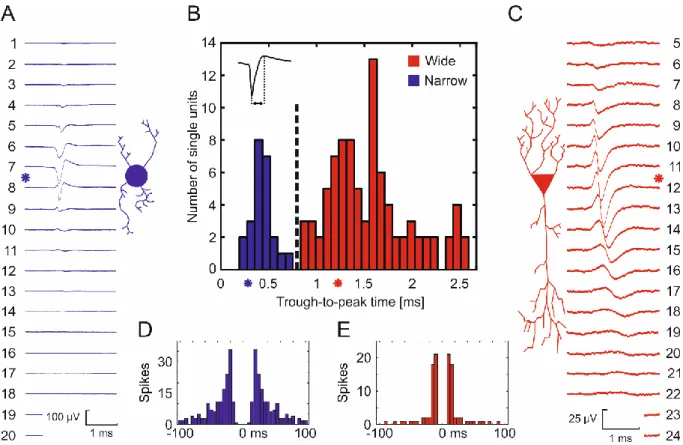
We report all single unit data obtained using the spiky probe in Figure 7/B. We used a hierarchical clustering for separating the recorded EAPs into putative cell types based on their through-to-peak times. Based on the clustering results, spike waveforms having a trough-to- peak time below 0.8 ms were classified as putative interneurons (narrow spikes), while
remaining clusters were considered as putative principal cells (wide spikes). In addition, two representative datasets (Figure 7/A &C) illustrate how the close-packed contact sites of the high-density spiky probe (with 25 µm inter-contact distances) can spatio-temporally sample a single unit EAP. These data also describe how the waveform of the EAP can vary over distance, across several adjacent contact sites. We show the average EAP waveforms and the corresponding autocorrelograms of two different single units recorded with the same probe at the experiment. Autocorrelograms (Figures 7/D &E) were plotted in 100 ms duration and divided into 5 ms bins. The sharpest signals (where the waveform has the shortest temporal extent) were detected at Channel #8 (Figure 7/A) and Channel #12 (Figure 7/C). The spike counts over a recording duration of 3 minutes were #312 and #158, respectively. Based on the work of Bartho et al. 2004 and Csicsvari et al. 1999, the trough-to-peak time (or the half- width) of spikes itself may be enough for separating two groups of spikes from the recorded SUAs [56], [58], as it is shown in Figure 7/B. Here we investigated additional parameters in the case of two selected single units, namely trough-to-peak time, presence of the capacitive peak, features in the autocorrelogram and spatial spread. The second single unit (shown in red) had a trough-to-peak time of 1.2 ms at the sharpest channel, 4 times longer compared to 0.3 ms of the first unit (shown in blue). Moreover, we found that the initial positive peak on the second unit (red) was present on numerous contributing channels while the first unit (blue) exhibited the initial positive peak visibly only at the sharpest channel. Investigating the autocorrelograms, the first unit (blue) showed distributed firing patterns resulting in a smooth decay in the histogram (Figure 7/D). In contrast, the second unit (red) showed fast and regular-spiking behaviour, resulting in a narrow-range and sharp peak on the autocorrelogram close to the middle refractory period (Figure 7/E). The initial steepness was higher for the second unit (red) represented by the immediate peak after the refractory period, unlike the first unit (blue), where the initial peak was built from intermediate steps. Referring to Bartho
et al. 2004 [56] and Csicsvari et al. 1999 [58], we clustered the first single unit (blue) to a putative interneuron and the second single unit (red) to a putative pyramidal cell. Lastly, please also note the different spatial propagation of the EAP across channels. In the case of putative pyramidal cell, the signal propagation was rather bi-directional and also longer compared to the putative interneuron. The propagation of the putative interneuron was less significant and almost unidirectional. Interestingly, the more localised putative interneuron had higher peak-to-peak amplitude of 162 µV while the putative pyramidal cell only had 72 µV. Such differences can however be also emerged from the variable Euclidean distances and orientation of the cells compared to the axis of the laminar probe. The determination of these parameters remains to be investigated in future experimental paradigms.
Figure 7 – Clustering results of putative cell types based on their recorded extracellular waveforms. A: Averaged extracellular traces of a putative interneuron (shown in blue) with corresponding autocorrelogram (D, blue). B: Bimodal distribution of trough-to-peak times of recorded single unit waveforms. Hierarchical clustering was used to separate units (shown in black dashed line) either as narrow spiking (blue) or as wide spiking (red) neurons (i.e. as putative inhibitory interneurons or excitatory principal cells, respectively). Asterisks represent trough-to-peak times of the two selected units. C: Averaged extracellular traces of a putative pyramidal cell (shown in red) with corresponding autocorrelogram (E, red).
Asterisks next to the spike waveforms represent the sharpest signals (possibly the closest contact sites to the soma). Please note the different propagation lengths and different spiking behaviour of the two putative cell types.
Conclusions and outlook
In this study, we have presented and tested a penetrating spiky probe for extracellular recordings, in vitro. The fabrication process and packaging method allow for creating different layouts with inter-contact distances ranging from 25 µm up to 100 µm. The arrowhead-like contact sites are detached from the main axis of the shank and thus enable a slight penetration beneath the surface of the brain slice. Thanks to these protruding contact sites, the spiky probe can record from a deeper neural tissue environment resulting in higher spike amplitudes as well as a higher single unit yield compared to a commercially available surface probe [46], [50]. We reported that every single insertion yielded single unit activity which was frequently accompanied by sharp wave population activity. The spatio-temporally sampled EAPs were visible on multiple contact sites and preliminary clustering methods were applied for separating putative cell type based on their waveform differences.
It has to be admitted that the current experimental approach is not designed for long-term recordings. Our main focus was to increase the cell accessibility of the contact sites during acute brain slice recordings, consequently, to increase signal yield and recording quality.
Future developments may enable such devices to be applied in both chronic and acute recordings, as well as in combination with other modalities such as intracellular recordings, combined optogenetics or microfluidic drug delivery applications [59], [60]. We showed an example for combined two-photon imaging and proposed that our spiky probe makes possible consecutive recording and imaging of the tissue at the same region. However, the stability of multi-layered contact sites under two-photon laser scanning is to yet be investigated. In addition, as only the contact sites penetrate into the deeper tissue, they may cause less tissue damage than commercially available penetrating probes, but a proper histological validation is also to be performed. Lastly, we propose one more advantage of our design, namely that we can overcome the so called ‘dead-spot problem’ [61]. A dead-spot problem appears when the
contact sites along the shank are located too far from the tip or the edge of the shank. It becomes difficult or even impossible to approach and record from the closest active cells by an intracellular glass micropipette, simultaneously, as the probe itself attenuates the neighbouring signals. Recent works in the literature showed how these paired intra- and extracellular recordings could make new ground-truth data for multi-channel extracellular electrophysiology [32], [61], [62]. With our protruding design, such co-localised recordings may become easier to perform and to achieve higher signal amplitudes. Moreover, the angled shank can fit under the objective of a two-photon laser scanning microscope, thus it is also possible to complete the electrophysiological data with subsequent optical and structural information. We conclude that our spiky probe can be a step towards multi-modal experimental designs while they also expand the limits and neural yield achievable by laminar multi-channel electrophysiological systems.
Author Contributions
D. M., P. R., G. M. and I. U. conceived the project, D. M., B. P. K., G.M., T. H. and P. R.
designed the spiky probe, T. H. and P. R. performed the fabrication process of the probe. D.
M., B. P. K. and I. P. executed the experiments, D. M., G. O., R. F. executed the analysis. D.
M., P. R., R. F., G. M. and I. U. wrote the main manuscript. The manuscript was reviewed by all authors before submission.
Disclosure
The authors declare no conflict of interests.
Acknowledgements
This research has been partially funded by the Hungarian Brain Research Program (Grant No.
KTIA_13_NAP-A-IV/1,2,3,4,6. and 2017-1.2.1-NKP-2017-00002) and VEKOP-2.3.2-16- 2017-00013. D. M. is thankful for the New National Excellence Program of the Ministry of Human Capacities (ÚNKP-18-3-III-PPKE-35). R. F. is thankful to the Hungarian National Research, Development and Innovation Office (PD124175).
References
[1] D. H. Hubel, “Tungsten microelectrode for recording from single units,” Science (80-.
)., vol. 125, no. 3247, pp. 549–550, 1957.
[2] C. M. Gray, P. E. Maldonado, M. Wilson, and B. McNaughton, “Tetrodes markedly improve the reliability and yield of multiple single-unit isolation from multi-unit recordings in cat striate cortex,” J. Neurosci. Methods, vol. 63, no. 1–2, pp. 43–54, 1995.
[3] D. a Henze, Z. Borhegyi, J. Csicsvari, A. Mamiya, K. D. Harris, and G. Buzsáki,
“Intracellular features predicted by extracellular recordings in the hippocampus in vivo.,” J. Neurophysiol., vol. 84, no. 1, pp. 390–400, 2000.
[4] J. Csicsvari, D. A. Henze, B. Jamieson, K. D. Harris, A. Sirota, P. Barthó, K. D. Wise, and G. Buzsáki, “Massively parallel recording of unit and local field potentials with silicon-based electrodes.,” J. Neurophysiol., vol. 90, no. 2, pp. 1314–23, 2003.
[5] G. Buzsáki, “Large-scale recording of neuronal ensembles,” Nat. Neurosci., vol. 7, no.
5, pp. 446–451, 2004.
[6] L. Grand, A. Pongrácz, É. Vázsonyi, G. Márton, D. Gubán, R. Fiáth, B. P. Kerekes, G.
Karmos, I. Ulbert, and G. Battistig, “A novel multisite silicon probe for high quality laminar neural recordings,” Sensors Actuators A Phys., vol. 166, no. 1, pp. 14–21, Mar.
2011.
[7] M. Lanzilotto, A. Livi, M. Maranesi, M. Gerbella, F. Barz, P. Ruther, L. Fogassi, G.
Rizzolatti, and L. Bonini, “Extending the cortical grasping network: Pre-supplementary motor neuron activity during vision and grasping of objects,” Cereb. Cortex, vol. 26, no. 12, pp. 4435–4449, 2016.
[8] T. J. Blanche, “Polytrodes: High-Density Silicon Electrode Arrays for Large-Scale Multiunit Recording,” J. Neurophysiol., vol. 93, no. 5, pp. 2987–3000, 2005.
[9] Z. Fekete and A. Pongracz, “Multifunctional soft implants to monitor and control neural activity in the central and peripheral nervous system: A review,” Sensors Actuators, B Chem., vol. 243, no. December, pp. 1214–1223, 2017.
[10] A. Altuna, L. Menendez de la Prida, E. Bellistri, G. Gabriel, A. Guimerá, J. Berganzo, R. Villa, and L. J. Fernández, “SU-8 based microprobes with integrated planar electrodes for enhanced neural depth recording,” Biosens. Bioelectron., vol. 37, no. 1, pp. 1–5, 2012.
[11] N. Xue, D. Wang, C. Liu, Z. Ke, P. Elia, T. Li, C. Chi, Y. Cheng, and J. Sun, “A biodegradable porous silicon and polymeric hybrid probe for electrical neural signal recording,” Sensors Actuators, B Chem., vol. 272, no. March, pp. 314–323, 2018.
[12] C. Boehler, C. Kleber, N. Martini, Y. Xie, I. Dryg, T. Stieglitz, U. G. Hofmann, and M.
Asplund, “Actively controlled release of Dexamethasone from neural microelectrodes in a chronic in vivo study,” Biomaterials, vol. 129, pp. 176–187, 2017.
[13] M. E. J. Obien, K. Deligkaris, T. Bullmann, D. J. Bakkum, and U. Frey, “Revealing
neuronal function through microelectrode array recordings,” Front. Neurosci., vol. 9, no. JAN, p. 423, 2015.
[14] J. P. Seymour, F. Wu, K. D. Wise, and E. Yoon, “State-of-the-art MEMS and microsystem tools for brain research,” Microsystems Nanoeng., vol. 3, no. March 2016, p. 16066, 2017.
[15] A. A. Fomani and R. R. Mansour, “Fabrication and characterization of the flexible neural microprobes with improved structural design,” Sensors Actuators, A Phys., vol.
168, no. 2, pp. 233–241, 2011.
[16] J. Scholvin, J. Kinney, J. Bernstein, C. Moore-Kochlacs, N. Kopell, C. Fonstad, and E.
Boyden, “Close-Packed Silicon Microelectrodes for Scalable Spatially Oversampled Neural Recording,” Biomed. Eng. IEEE Trans., vol. PP, no. 99, p. 1, 2015.
[17] B. C. Raducanu, R. F. Yazicioglu, C. M. Lopez, M. Ballini, J. Putzeys, S. Wang, A.
Andrei, V. Rochus, M. Welkenhuysen, N. van Helleputte, and others, “Time Multiplexed Active Neural Probe with 1356 Parallel Recording Sites,” Sensors, vol. 17, no. 10, p. 2388, 2017.
[18] R. Fiáth, B. C. Raducanu, S. Musa, A. Andrei, C. M. Lopez, C. van Hoof, P. Ruther, A.
Aarts, D. Horváth, and I. Ulbert, “A silicon-based neural probe with densely-packed low-impedance titanium nitride microelectrodes for ultrahigh-resolution in vivo recordings,” Biosens. Bioelectron., vol. 106, no. January, pp. 86–92, 2018.
[19] J. J. Jun, N. A. Steinmetz, J. H. Siegle, D. J. Denman, M. Bauza, B. Barbarits, A. K.
Lee, C. A. Anastassiou, A. Andrei, Ç. Aydin, M. Barbic, T. J. Blanche, V. Bonin, J.
Couto, B. Dutta, S. L. Gratiy, D. A. Gutnisky, M. Häusser, B. Karsh, P.
Ledochowitsch, C. M. Lopez, C. Mitelut, S. Musa, M. Okun, M. Pachitariu, J. Putzeys, P. D. Rich, C. Rossant, W. L. Sun, K. Svoboda, M. Carandini, K. D. Harris, C. Koch, J.
O’Keefe, and T. D. Harris, “Fully integrated silicon probes for high-density recording of neural activity,” Nature, vol. 551, no. 7679, pp. 232–236, 2017.
[20] K. Seidl, M. Schwaerzle, I. Ulbert, H. P. Neves, O. Paul, and P. Ruther, “CMOS-Based High-Density Silicon Microprobe Arrays for Electronic Depth Control in Intracortical Neural Recording - Characterization and Application,” Microelectromechanical Syst.
J., vol. 21, no. 6, pp. 1426–1435, 2012.
[21] T. Torfs, A. A. A. Aarts, M. A. Erismis, J. Aslam, R. F. Yazicioglu, K. Seidl, S.
Herwik, I. Ulbert, B. Dombovari, R. Fiáth, B. P. Kerekes, R. Puers, O. Paul, P. Ruther, C. Van Hoof, and H. P. Neves, “Two-dimensional multi-channel neural probes with electronic depth control,” IEEE Trans. Biomed. Circuits Syst., vol. 5, no. 5, pp. 403–
412, 2011.
[22] G. Dimitriadis, J. P. Neto, A. Aarts, A. Alexandru, M. Ballini, F. Battaglia, L.
Calcaterra, F. David, R. Fiath, J. Frazao, J. P. Geerts, L. J. Gentet, N. Van Helleputte, T. Holzhammer, C. van Hoof, D. Horvath, G. Lopes, C. M. Lopez, E. Maris, A.
Marques-Smith, G. Marton, B. L. McNaughton, D. Meszena, S. Mitra, S. Musa, H.
Neves, J. Nogueira, G. A. Orban, F. Pothof, J. Putzeys, B. Raducanu, P. Ruther, T.
Schroeder, W. Singer, P. Tiesinga, I. Ulbert, S. Wang, M. Welkenhuysen, and A. R.
Kampff, “Why not record from every channel with a CMOS scanning probe?,”
bioRxiv, no. Ic, p. 275818, 2018.
[23] A. S. Herbawi, S. Member, O. Christ, L. Kiessner, S. Mottaghi, U. G. Hofmann, O.
Paul, S. Member, and P. Ruther, “CMOS Neural Probe With 1600 Close-Packed Recording Sites and 32 Analog Output Channels,” J. Microelectromechanical Syst., no.
October, 2018.
[24] A. Maccione, A. Simi, T. Nieus, M. Gandolfo, K. Imfeld, E. Ferrea, E. Sernagor, and L. Berdondini, “Sensing and actuating electrophysiological activity on brain tissue and neuronal cultures with a high-density CMOS-MEA,” 2013 Transducers Eurosensors XXVII 17th Int. Conf. Solid-State Sensors, Actuators Microsystems, TRANSDUCERS EUROSENSORS 2013, no. June, pp. 752–755, 2013.
[25] D. Tsai, D. Sawyer, A. Bradd, R. Yuste, and K. L. Shepard, “A very large-scale microelectrode array for cellular-resolution electrophysiology,” Nat. Commun., vol. 8, no. 1, 2017.
[26] J. Dragas, V. Viswam, A. Shadmani, Y. Chen, R. Bounik, A. Stettler, M. Radivojevic, S. Geissler, M. E. J. Obien, J. Müller, and A. Hierlemann, “In Vitro Multi-Functional Microelectrode Array Featuring 59 760 Electrodes, 2048 Electrophysiology Channels, Stimulation, Impedance Measurement, and Neurotransmitter Detection Channels,”
IEEE J. Solid-State Circuits, vol. 52, no. 6, pp. 1576–1590, 2017.
[27] O. Herreras, “Local Field Potentials: Myths and Misunderstandings,” Front. Neural Circuits, vol. 10, no. December, pp. 1–16, 2016.
[28] G. T. Einevoll, C. Kayser, N. K. Logothetis, and S. Panzeri, “Modelling and analysis of local field potentials for studying the function of cortical circuits,” Nat. Rev. Neurosci., vol. 14, no. 11, pp. 770–785, 2013.
[29] K. D. Harris, R. Q. Quiroga, J. Freeman, and S. L. Smith, “Improving data quality in neuronal population recordings,” Nat. Neurosci., vol. 19, no. 9, pp. 1165–1174, 2016.
[30] N. A. Steinmetz, C. Koch, K. D. Harris, and M. Carandini, “Challenges and opportunities for large-scale electrophysiology with Neuropixels probes,” Curr. Opin.
Neurobiol., vol. 50, pp. 92–100, 2018.
[31] W. L. Shew, T. Bellay, and D. Plenz, “Simultaneous multi-electrode array recording and two-photon calcium imaging of neural activity,” J. Neurosci. Methods, vol. 192, no. 1, pp. 75–82, 2010.
[32] A. Marques-smith, J. P. Neto, G. Lopes, L. Calcaterra, J. Frazão, D. Kim, M. G.
Phillips, G. Dimitriadis, and A. R. Kampff, “Recording from the same neuron with high-density CMOS probes and patch-clamp : a ground-truth dataset and an experiment in collaboration .,” 2018.
[33] Y. Kajikawa and C. E. Schroeder, “How local is the local field potential?,” Neuron, vol. 72, no. 5, pp. 847–858, 2011.
[34] K. H. Pettersen and G. T. Einevoll, “Amplitude variability and extracellular low-pass filtering of neuronal spikes,” Biophys. J., vol. 94, no. 3, pp. 784–802, 2008.
[35] K. H. Pettersen, H. Lindén, A. M. Dale, and G. T. Einevoll, “Extracellular spikes and CSD,” Handb. neural Act. Meas., vol. 1, pp. 92–135, 2012.
[36] G. Buzsáki, C. a. Anastassiou, and C. Koch, “The origin of extracellular fields and
currents — EEG, ECoG, LFP and spikes,” Nat. Rev. Neurosci., vol. 13, no. June, pp.
407–420, 2012.
[37] K. M. Scott, J. Du, H. A. Lester, and S. C. Masmanidis, “Variability of acute extracellular action potential measurements with multisite silicon probes,” J. Neurosci.
Methods, vol. 211, no. 1, pp. 22–30, 2012.
[38] J. P. Neto, P. Baião, G. Lopes, J. Frazão, J. Nogueira, E. Fortunato, P. Barquinha, and A. R. Kampff, “Does impedance matter when recording spikes with polytrodes?,”
bioRxiv, p. 270058, 2018.
[39] Z. Bérces, K. Tóth, G. Márton, I. Pál, B. Kováts-Megyesi, Z. Fekete, I. Ulbert, and A.
Pongrácz, “Neurobiochemical changes in the vicinity of a nanostructured neural implant,” Sci. Rep., vol. 6, no. June, pp. 1–11, 2016.
[40] S. M. Wellman and T. D. Y. Kozai, “Understanding the Inflammatory Tissue Reaction to Brain Implants to Improve Neurochemical Sensing Performance,” ACS Chem.
Neurosci., vol. 8, no. 12, pp. 2578–2582, 2017.
[41] N. Hájos, T. J. Ellender, R. Zemankovics, E. O. Mann, R. Exley, S. J. Cragg, T. F.
Freund, and O. Paulsen, “Maintaining network activity in submerged hippocampal slices: Importance of oxygen supply,” Eur. J. Neurosci., vol. 29, no. 2, pp. 319–327, 2009.
[42] A. Segev, F. Garcia-Oscos, and S. Kourrich, “Whole-cell Patch-clamp Recordings in Brain Slices,” J. Vis. Exp., no. 112, pp. 1–10, 2016.
[43] M. O. Heuschkel, C. Wirth, E. Steidl, and B. Buisson, Chapter 4 Development of 3D Multi Electrode Arrays for Use with Acute Tissue Slices, no. June 2016. 2006.
[44] S. Rajaraman, M. a Mcclain, S. Choi, J. D. Ross, P. Stephen, M. C. Laplaca, and M. G.
Allen, “Three-dimensional metal transfer micromolded microelectrode ar- rays (mea,”
Transducers Eurosensors 2007 14th Int. Conf. Solid-State Sensors, Actuators Microsystems, Lyon, Fr., vol. 8, pp. 1251–1254, 2007.
[45] L. Wittner, G. Huberfeld, S. Clémenceau, L. Erss, E. Dezamis, L. Entz, I. Ulbert, M.
Baulac, T. F. Freund, Z. Maglóczky, and R. Miles, “The epileptic human hippocampal cornu ammonis 2 region generates spontaneous interictal-like activity in vitro,” Brain, vol. 132, no. 11, pp. 3032–3046, 2009.
[46] B. P. Kerekes, K. Tóth, A. Kaszás, B. Chiovini, Z. Szadai, G. Szalay, D. Pálfi, A.
Bagó, K. Spitzer, B. Rózsa, I. Ulbert, and L. Wittner, “Combined two-photon imaging, electrophysiological, and anatomical investigation of the human neocortex in vitro,” Neurophotonics, vol. 1, p. 011013, 2014.
[47] Y. Lu, T. Wang, Z. Cai, Y. Cao, H. Yang, and Y. Y. Duan, “Anodically electrodeposited iridium oxide films microelectrodes for neural microstimulation and recording,” Sensors Actuators, B Chem., vol. 137, no. 1, pp. 334–339, 2009.
[48] S. Herwik, O. Paul, and P. Ruther, “Ultrathin Silicon Chips of Arbitrary Shape by Etching Before Grinding,” JMEMS Lett., vol. 20, no. 4, pp. 1–3, 2011.
[49] F. Laermer and A. Urban, “Challenges, developments and applications of silicon deep reactive ion etching,” Microelectron. Eng., vol. 67–68, pp. 349–355, 2003.
[50] L. Wittner, G. Huberfeld, S. Clémenceau, L. Erss, E. Dezamis, L. Entz, I. Ulbert, M.
Baulac, T. F. Freund, Z. Maglóczky, and R. Miles, “The epileptic human hippocampal cornu ammonis 2 region generates spontaneous interictal-like activity in vitro,” Brain, vol. 132, no. 11, pp. 3032–3046, 2009.
[51] B. P. Kerekes, K. Tóth, A. Kaszás, B. Chiovini, Z. Szadai, G. Szalay, D. Pálfi, A.
Bagó, K. Spitzer, B. Rózsa, I. Ulbert, and L. Wittner, “Combined two-photon imaging, electrophysiological, and anatomical investigation of the human neocortex in vitro,”
Neurophotonics, vol. 1, no. 1, p. 011013, 2014.
[52] J. T. Ting, T. L. Daigle, Q. Chen, and G. Feng, “Acute brain slice methods for adult and aging animals: application of targeted patch clampanalysis and optogenetics,”
Methods Mol Biol., no. 1183, p. 221–242., 2014.
[53] M. Pachitariu, N. Steinmetz, S. Kadir, M. Carandini, and K. D. Harris, “Kilosort:
realtime spike-sorting for extracellular electrophysiology with hundreds of channels,”
bioRxiv, p. 061481, 2016.
[54] M. Pachitariu, N. A. Steinmetz, S. N. Kadir, M. Carandini, and K. D. Harris, “Fast and accurate spike sorting of high-channel count probes with KiloSort,” Adv. Neural Inf.
Process. Syst., vol. 29, no. Nips, pp. 4448–4456, 2016.
[55] R. Fiáth, A. L. Márton, F. Mátyás, D. Pinke, G. Márton, K. Tóth, and I. Ulbert, “Slow insertion of silicon probes improves the quality of acute neuronal recordings,” Sci.
Rep., vol. 9, no. 1, p. 111, 2019.
[56] P. Bartho, H. Hirase, L. Monconduit, M. Zugaro, K. D. Harris, and G. Buzsaki,
“Characterization of Neocortical Principal Cells and Interneurons by Network Interactions and Extracellular Features,” J. Neurophysiol., vol. 92, no. 1, pp. 600–608, 2004.
[57] J. H. Ward, “Hierarchical Grouping to Optimize an Objective Function Author,” J. Am.
Stat. Assoc., vol. 58, no. 301, pp. 236–244, 1963.
[58] J. Csicsvari, H. Hirase, a Czurkó, a Mamiya, and G. Buzsáki, “Oscillatory coupling of hippocampal pyramidal cells and interneurons in the behaving Rat.,” J. Neurosci., vol.
19, no. 1, pp. 274–287, 1999.
[59] Z. Fekete, E. Pálfi, G. Márton, M. Handbauer, Z. Bérces, I. Ulbert, A. Pongrácz, and L.
Négyessy, “Combined in vivo recording of neural signals and iontophoretic injection of pathway tracers using a hollow silicon microelectrode,” Sensors Actuators, B Chem., vol. 236, pp. 815–824, 2016.
[60] A. Zátonyi, Z. Borhegyi, M. Srivastava, D. Cserpán, Z. Somogyvári, Z. Kisvárday, and Z. Fekete, “Functional brain mapping using optical imaging of intrinsic signals and simultaneous high-resolution cortical electrophysiology with a flexible, transparent microelectrode array,” Sensors Actuators, B Chem., vol. 273, no. February, pp. 519–
526, 2018.
[61] J. P. Neto, G. Lopes, J. Frazão, J. Nogueira, P. Lacerda, P. Baião, A. Aarts, A. Andrei, S. Musa, E. Fortunato, P. Barquinha, and A. R. Kampff, “Validating silicon polytrodes with paired juxtacellular recordings: method and dataset,” J. Neurophysiol., vol. 116, no. 2, pp. 892–903, 2016.
[62] B. D. Allen, C. Moore-Kochlacs, J. G. Bernstein, J. P. Kinney, J. Scholvin, L. F.
Seoane, C. Chronopoulos, C. Lamantia, S. B. Kodandaramaiah, M. Tegmark, and E. S.
Boyden, “Automated in vivo patch clamp evaluation of extracellular multielectrode array spike recording capability,” J. Physiol., vol. 120, no. 5, pp. 2182-2200, 2018.