DESIGN CONSIDERATIONS FOR
A RE-ENTRY VEHICLE THERMAL PROTECTION SYSTEM J.H. Bridges^* and F.D. Richmond^
Chance Vought Corp», D a l l a s , Texas ABSTRACT
The design parameters f o r a re-entry vehicle thermal protec- tion system are examined. These parameters are considered in the development of a thermal protection system which u t i l i z e s an optimum combination of a heat shield, high temperature i n - sulation, metallic vapor b a r r i e r and Thermosorb — a Vought developed high water content expendable heat sink.
INTRODUCTION
I t i s common knowledge that vehicles returning to Earth from o r b i t a l or space missions experience elevated surface tempera- tures due to aerodynamic heating. Although ablative and/or radiative cooling methods are used to l i m i t surface tempera- tures, weight optimization leads to the use of the higher temp- eratures in order to use l e s s ablative and more r a d i a t i v e cool- ing. The result i s that the l i g h t e s t surface system tends to be the one that operates at the highest temperature.
These high surface temperatures create the need for a system to prevent excessive temperatures within the vehicle. Such a system i s possible by using a combination of insulation and heat sink in the vehicle w a l l s , and i t i s that type of system
that i s the subject of this paper. F i r s t , an insulation i s Presented at the ARS Lunar Missions Meeting, Cleveland, Ohio, July 17-19, 1962.
The design considerations and conclusions presented are de- rived from work conducted on U . S . Air Force Contract AF33(6l6)- 7829, "Structural integration of thermosorb", interim report (December 1961).
•^•Lead Engineer, Technologies R & D , Astronautics Division»
^Associate Engineer, Power and Environment, Astronautics Division.
used as p a r t i a l p r o t e c t i o n against the high outside tempera- t u r e . Second, a heat sink capable o f absorbing and disposing o f heat at compartment temperatures i s used.
Vought A s t r o n a u t i c s developed a high water content semi- s o l i d heat sink m a t e r i a l now known as Thermo sorb. This ma- t e r i a l , i l l u s t r a t e d i n F i g . 1. i s a high water content semi- s o l i d g e l r e t a i n e d by an open c e l l sponge and sealed i n a thermoplastic c o n t a i n e r . The sponge p r o v i d e s mechanical r e - t e n t i o n f o r the a c c e l e r a t i o n - r e s i s t a n t g e l . The container p r e - vents evaporation during s t o r a g e or space operations and melts upon exposure to r e - e n t r y h e a t i n g t o a c t i v a t e the system.
Thermosorb has been subjected t o v i b r a t i o n , ngH- l o a d i n g , tem- perature v a r i a t i o n s , e t c . , to demonstrate i t s a b i l i t y to p e r - form s a t i s f a c t o r i l y under the v a r i o u s conditions o f space t r a v e l .
ΐΛ/hile Thermosorb was being developed, a contract was nego- t i a t e d with ASD f o r a Thermosorb-structural i n t e g r a t i o n p r o - gram. The contract required the d e s i g n i n g , building and t e s t - ing o f panels f o r use on r e - e n t r y v e h i c l e s . These panels would separate the cooled compartment from the high tempera- tures o f r e - e n t r y and provide the r e q u i r e d s t r u c t u r a l strength and thermal p r o t e c t i o n f o r the v e h i c l e .
This paper presents some useful methods o f thermal analysis for use i n the design o f a thermal p r o t e c t i o n system, examines the parametric r e l a t i o n s i n v o l v e d , and describes t e s t r e s u l t s for comparisons with a n a l y t i c a l work.
The basic system considered i s shown i n F i g . 2 with the sys- tem components described as f o l l o w s : 1 ) an outside heat s h i e l d which c o o l s i t s e l f by r a d i a t i v e and/or a b l a t i v e methods, 2) a l a y e r o f i n s u l a t i o n to impede the transfer o f heat t o the i n - s i d e compartment, 3 ) si vapor b a r r i e r t o prevent steam from the Thermosorb from entering the i n s u l a t i o n , \±) a space between the vapor b a r r i e r and Thermosorb to p r o v i d e an e x i t f o r the steam, 5 ) a l a y e r o f ftiermosorb t o absorb the heat transmitted from the hot e x t e r i o r surface, 6 ) a c o l d w a l l to p r o v i d e the basic v e h i c l e s t r u c t u r e , 7 ) supports from the c o l d w a l l f o r the vapor b a r r i e r and the e x t e r i o r heat s h i e l d s , and 8 ) a steam venting system.
-^Systems i n which the steam l e a v e s the v e h i c l e through the i n s u l a t i o n are p o s s i b l e . However, such systems are not analyzed i n t h i s paper.
SYSTEM ANALYSIS
From the viewpoint of heat transfer engineering, the prob- lems associated with system analysis can be separated into three groups. F i r s t i s the problem of weight as a function of the r e l a t i v e amounts of insulation and heat sink. Second i s the problem of weight due to heat shorts. Heat shorts are those structural members necessary to support the vapor barrier and heat shields. Such structure, in terms of heat transfer, provides "shorts" from the hot side to the cold side. F i n a l l y ,
the problem of weight and space required for steam vents i s considered. This emphasis upon weight i s made with the under- standing that r e l i a b i l i t y and performance requirements w i l l be maintained during the weight reduction process.
Insights into insulation and heat sink weight optimization can be determined by computer methods which simply hold con- stant a number o f parameters and vary the thickness of insula- tion. When the system weight i s plotted against insulation thickness, the minimum weight is found to exist at or near the condition where the weight of the insulation i s equal to the weight of the heat sink. Such a plot is shown by F i g . 3·
From a rigorous viewpoint, the plot applies only to the par- t i c u l a r set of values used for the independent parameters.
These independent parameters include such items as heat sink temperature, radiation factor from vapor b a r r i e r to heat sink, and insulation conductivity and density. Thus, numerical c a l - culations to determine optimum quantities of insulation and heat sink give particular answers as contrasted to general answers.
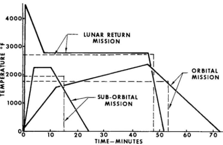
Based upon the foregoing considerations, a series of mathe- matical simplifications were explored in order to understand better the effects of changes in the many independent v a r i - a b l e s . As working models, three temperature-time p r o f i l e s were selected to represent suborbital, o r b i t a l , and lunar return re-entry conditions. These p r o f i l e s are shown by solid l i n e s by Fig. U. Although the straight l i n e s in themselves represent simplifications, the mathematical equations associ- ated with varying hot side temperatures are cumbersome and not r e a d i l y adaptable to manipulation. In addition, i t i s known that the insulation and vapor b a r r i e r w i l l not contribute much as heat sinks. Therefore, i t was decided to transform the selected temperature-time p r o f i l e s into rectangular pulses and, for the time being, ignore a l l heat sinks other than the Thermo- sorb i t s e l f . The transformed p r o f i l e s are shown by dotted l i n e s in F i g . U. Each p r o f i l e has an exact transformation, and each rectangular pulse represents a family of p r o f i l e s . Whether or
not the chosen transformation includes the exact i n i t i a l pro- f i l e i s somewhat immaterial in establishing parametric r e - l a t i o n s . After the relations are established and used in panel design, f i n a l optimization of panel weight by use of com- puter methods and the i n i t i a l p r o f i l e insure that no accuira*- lation of error w i l l e x i s t .
In working with rectangular pulses and steady-state heat transfer equations, the mathematical d i f f i c u l t i e s are reduced, and important parametric relations are determined. In setting up equations suitable for determination of minimums by the methods of d i f f e r e n t i a l calculus, i t is found that the depen-
dent temperature of the vapor b a r r i e r involves a fourth order algebraic expression with an eleventh order derivative. I t i s obvious by simple substitution that the weight of the insula- tion being equal to the weight of the heat sink does not s a t i s - fy the derived equation. Neverthe l e s s , crossplots of solu- tions obtained by computer methods show minimum weights at or near the equal weights condition for a v a r i e t y of insulations.
Part of the mathematical d i f f i c u l t y arises from the simple fact that high order algebraic equations are cumbersome. How- ever, much of the problem can be expressed in simple l i n e a r r e l a t i o n s . For example, the rate of heat transfer from the hot side to the heat sink can be written simply as
%
- - Κ δ τ / % LG
where the symbols are l i s t e d at the end of the paper and Δ Τ i s the temperature drop across the insulation. Further, the weight of the heat sink i s
^ - W K [ 2 ]
and the weight of the insulation i s
W
t çx tel
The weight of the heat sink plus the weight of this insulation is
V/
sW
w+ W
L [A]By substitution
W
s= ( K A T e / % ^
f 8) ç% [5]
The condition that χ be the only variable on the right-hand side of the equation i s that there be no thermal resistance
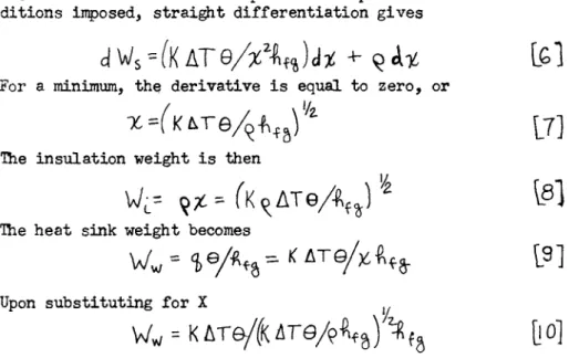
between the insulation and the heat sink. In other words, the insulation takes a l l the temperature drop. With such con- ditions imposed, straight differentiation gives
d W
s= ( K A T e / # \
%) d # + - Q « U fel
For a minimum, the derivative i s equal to zero, or
X=(KLTe/^
b)
l/i\J]
The insulation weight i s then
WL= = ( Κ ^ Δ Τ θ/ 4 %Γ) Vz \β]
The heat sink weight becomes
Upon substituting f o r X
Ww = Κ Δ Τ θ / ( Κ Δ Τ Θ / 9 ^ 8) ^ [ 1 0 ]
I r l i c h i s the same expression as was obtained for the weight of
the insulation.
I t i s to be noted that the foregoing derivation did not allow for thermal resistance between the vapor b a r r i e r and the heat sink. When such allowance i s made, the equations, using
f ^ a s a parameter, become
Fig. 5 shows a p l o t of component weight and t o t a l weight versus barrier temperature with Kç as a parameter. Fixed typical values as shown were used for other parameters. The insulation parameter was assigned two values — 0.5 and 3>·0 (Refrasil A-100 has a Kç of about 0 . 5 ) · Calculations were made by assigning values to "T"v& y and then computing the weight figures. The process reveals important cues as to what determines minimum weight.
Notice that only one curve e x i s t s for the heat sink weight
^ / ^ , while two curves each are shown for the system weight yy/s and the insulation weight W j . For the 1-hr. time period considered, the required weight of the heat sink i s simply a fourth power function of T"v$ . In calculating the weight of the insulation, the term T ~v b appears as a f i r s t power in the numerator as a fourth power in the denominator. This means that the weight of __the insulation i s a modified inverse fourth power function of l ν Β · The system weight i s simply the sum of the two component weights. The insulation weight continu- ously decreases with increasing T V e , and the heat sink weight continuously increases with increasing "TVfc . The mini- mum system weight occurs when the slopes of the two__functions are equal. That i s , beginning with low values of I ^ and going upward, a point i s reached at which the next A Tvf e costs as much in heat sink weight as i s saved in insulation weight. Notice that the minimum system weight occurs at or near the point where the two component weights are equal, and, for the more r e a l i s t i c value of Kç * 0·5, the bottom of the system weight curve i s reasonably f l a t .
In the f i r s t simplified system in which there i s no vapor barrier or radiative resistance, i t is determined that the minimum-weight-system insulation requirement may be determined by equation 8. That i s , the required weight of the insulation would increase with the square root of the Kç> quantity for the
insulation. From Fig. i t i s noted that, for a Kç> B Q.5>, the system minimum weight i s 2 l b / f t 2 , and that, for a K ^ - 0.5, the system minimum weight i s 5·9 l b / f t 2 . The ratio of K ç » s i s 10, and the square root of 10 i s 3 · ΐ 6 . I f the square root r a t i o were true, then the weight of the heavy system extra- polated from the l i g h t e r system would be 2 times 3·16 = 6·32 l b / f t 2 as compared to the calculated and plotted value of 5o9 l b / f t 2#
The primary difference between the two numbers i s due to the radiative resistance which reduces requirements for both weight components. Nonetheless, the numbers serve to establish a criterion f o r insulation and show that i t i s better to com- pare the r a t i o of the square root of the Κ ζ values than i t i s to make comparisons on the b a s i s of Κ or ç or upon the f i r s t power of Kq ·
Another cue derived from Fig. ζ i s that, regardless of the type of insulation used, the minimum weight system w i l l have approximately equal weights of insulation and heat sink. This fact makes possible a technique for rapid hand calculations for use in exploring the effect of other independent v a r i a b l e s . For example, the effects upon optimum system weight of varying the radiation emissivity factor between the vapor b a r r i e r and the
Thermosorb are quite e a s i l y determined by only a few i t e r a t i o n s . By assigning f i x e d values to the other independent v a r i a b l e s , and using several values for the emissivity f a c t o r , i t i s p o s s i - ble to calculate the approximate optimum system weight for each emissivity value. This i s done by selecting a value for vapor b a r r i e r temperature, computing the heat radiated to the heat
sink, using the resulting heat sink weight as the insulation weight, and then computing the vapor b a r r i e r temperature i n
terms of the temperature drop from the heat shield to the vapor b a r r i e r . I t e r a t i o n i s used until the selected and computed vapor b a r r i e r temperatures agree. The weights used in the l a s t iteration represent the optimum system weight for that value of the emissivity factor. I/\Jhen such computations are completed, the system weight i s then plotted as a function of the emis- s i v i t y factor, and the desired relation i s obtained. Thus the addition of one equation, W */ 85 W d , represents a tool f a r more powerful than i s indicated by the simplicity of the equa- t i o n .
Although variations e x i s t in the use of the equal weights equation, a l l such methods are based upon the following: 1) the weight of insulation i s equal to the weight of the heat sink, 2) the heat transferred through the insulation i s equal to the heat absorbed by the heat sink, and 3) the temperature of the vapor b a r r i e r i s the same when approached from either side.
Ttie use of cross plots such as F i g s . 3 and 5 and the simpli- f i e d r e l a t i o n shown by y
can be used as the basis of extended parametric studies. For example, the heat of vaporization of water increases with de- creasing boiling temperatures. Reference to the foregoing equation shows that the approximate effect upon system weight due to decreasing cold wall temperatures i s to reduce the sys- tem weight by an amount inversely proportional to the square root of the r a t i o of the heats of evaporization. By treating superheat as an increase in ft f g , the same argument and approx:
mations may be used. Since Δ Τ i s the difference between the hot and cold sides, variations in these parameters are further traced by the same equation. F i n a l l y , note that the system weight increases with the square root of the time duration of the mission, © l i s means, f o r example, that the longer the mission, the lower the temperature of the vapor b a r r i e r , and vice versa. Equation 7 provides a f i r s t approximation to the insulation thickness when considering how thick the panel
should be while equation lU provides in algebraic form a f i r s t approximation to parametric r e l a t i o n s . Crossplots such as Fig*
3 a s s i s t in understanding the r e l a t i o n s . I t e r a t i v e calcu- lations using equations 1 and 13 and the assumption that W t
β W w provides r e a d i l y available numerical approximations.
F i n a l l y , computer methods r e f i n e the answers to provide true optimum design. The composite effect i s that the parametric relations are defined, understood, and reduced to design prac- t i c e .
The trajectory that w i l l be used on a re-entry mission de- pends upon many factors beyond the scope of this paper. One way to compare the effect that varying trajectories have upon the weight of the compartment cooling system i s to p l o t the system weight versus the t o t a l mission heat flux to the ve- h i c l e outer skin. Fig. 6 shows such a p l o t for varying heat fluxes due to different types of re-entry. A given mission probably would not have as much spread, but the trend would be approximately the same.
F i g . 6 also shows the effect of various values of Kç upon system weight. As expected, the greater the heat flux, the greater the effect that Kç has on the system.
Fig. 7 shows the effect of the emissivity factor between the vapor barrier and the Œiermosorb as well as the effect of vary- ing cold wall temperatures. The low emissivity factor appears attractive until the effects of Fig. 8 are considered. The lower vapor barrier temperatures associated with the higher emissivity factor of 0.5 would be much more desirable than an emissivity of 0.1 from this point of view.
By using the methods developed, the effects of any of the heat transfer-weight relations may be plotted, and those shown i l l u s t r a t e this idea.
Heat transfer from the hot side to the cold side by conduc- tion along the supporting structure i s known as "heat short11 effects. At f i r s t , i t would appear that the heat short effects could be simply calculated by use of variations of the conduc- tion equation. However, the interplay of heat transfer between the supports and the insulation, the effects of contact resist- ances, and the multitude of conduction paths lead to complex equivalent analog circuits.
The design of the supporting structure i s best begun only- after the general thickness of insulation and heat sink ma- t e r i a l has been established. For i n i t i a l working purposes,
the thickness allowed for the heat sink material should i n - clude enough vent area to prevent excessive steam velocities and should allow for the addition of heat sink to absorb the heat transferred by the structure. In general, this means that the allowed thickness for the heat sink and vent area w i l l be of the order of 0.2 to 0.3 in. compared to a much larger thickness for the insulation. Ihus the length of the supports can be estimated early in the preliminary design.
The area associated with each support w i l l depend to a large extent upon the design of the heat shield and the aerodynamic loading. In arriving at i n i t i a l designs, one of the things that must be considered is the manner of distributing the heat that is transferred by the supports. To do otherwise would be to invite hot spots on the cold w a l l .
As additional aids in assessing the final conductivity of the support configuration, i t i s convenient to develop r e s i s t - ance-capacitance transforms for circular washers, truncated prisms, and other geometric forms amenable to the methods of ordinary calculus. Sections of the supports then may be approxi- mated and assigned values of resistance and capacitance for use in both hand and computer calculations. Additional heat sink material i s needed to absorb the heat transferred by heat
shorts. This additional weight should be added to the weight of heat shorting structure in comparing proposed structural designs.
À number of useful concepts are available for use in steam system design. The ideal gas laws apply to most conditions, but i t i s much more convenient to use thermodynamic charts such as those of Ellenwood and Mackey.4 These charts plot enthalpy versus volume with parameters of pressure, tempera- ture, and entropy. The end points of processes such as throt- tling and isentropic expansions can be read directly from the charts, and the saving in time becomes significant.
For other purposes in which there i s no serious question about the degree of superheat so that the ideal gas laws apply, a useful plot i s that shown by Fig. 9. The plot shows the pressure ratio vs fL/D for varying inlet Mach numbers. fL/D is a parametric measure of fluid flow carrying capability of, for instance, a length of duct, and the pressure ratio i s the ratio
UEllenwood, F.O. and Mackey, C O . , Thermodynamic Charts (John Wiley and Sons, New York, 19U9), 2nd ed.
of outlet to inlet pressure. The limiting condition shows the pressure ratio that i s possible for given inlet Mach number.
The plot i s based upon adiabatic conditions and is usually found in textbooks on f l u i d flow. Fig. 9 also illustrates the importance of inlet Mach number on steam vent design. Notice that the median between pressure ratio and allowable fL/D occurs at or about an inlet Mach number of 0.1 instead of the intuitive 0.5 which i s halfway between no flow and choked flow.
The inlet Mach number i s limited by another consideration.
Velocities in excess of 0*1 acoustical velocity across the heat sink might cause excessive erosion of the heat sink material.
As such, the height of the vapor barrier above the heat sink should be sufficient to keep the Mach number down to the range of 0.1 for both possible scrubbing and pressure drop reasons.
The steam vent system might contain a pressure r e l i e f valve to keep the venting pressure from f a l l i n g below a given value even though such a valve is by no means a mandatory require- ment. I f a valve is used, a question arises as to whether or not the steam expansion w i l l cause freezing. In making this check, i t i s important to remember that the expansion process is more throttling than i t is isentropic. Reference to thermo- dynamic charts show the temperature drop associated with the constant enthalpy of throttling i s not near as great as in the case of isentropic expansion. Therefore, borderline freezing conditions uncovered by isentropic processes may well turn out to be of no importance.
Fig. 10 shows the required distance between the heat sink and vapor barrier when a square foot of area is vented a l l along one side. Notice the rapid increase with decreasing boiling temperatures. Fig. 11 shows the required valve flow area in square inches per square foot of panel for various heat sink temperatures. The numbers apply only to a specific vent con- figuration but serve to illustrate another important point. I f a heat sink temperature of, say, 80°F is selected for a given valve flow area and given heat rate input, the plot shows how the heat sink temperature w i l l r i s e with increasing heat inputs.
Conversely, the plot may be used to show the effects of a f a i l e d open valve. I f the valve f a i l s in the open position, the tem- perature drops, but the increasing steam volume i s so great in the region of ï>0°F that even the f a i l e d open valve chokes. In fact, suitable systems can be designed which use a fixed open- ing instead of a valve, and thus eliminate the only moving part in the system. After a vent system is designed from the fore- going considerations, the weight i s readily determined. Thus, several geometric arrangements can be considered.
TEST RESULTS
Two vehicle wall panels were fabricated for tests. These panels were designed to withstand 1800°F on the hot side. The heat sink material was used to maintain cold wall temperatures.
Tests were conducted using radiant heating lamps, thermocouples, and a special balance to measure weight l o s s . Thus the rate of heat transfer could be calculated from the measured rate of weight loss and the heat of vaporization of the heat sink ma- t e r i a l .
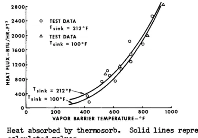
One of the f i r s t analytical assumptions tested was that the heat transfer from the vapor barrier to the heat sink would be by radiation with only negligible effects due to conduction and convection. Fig. 12 shows a plot of heat flux versus vapor barrier temperature. The close agreement of the data with a mathematical fourth order curve shows the validity of the as- sumption.
Fig. 13 shows the Kç under actual use as compared to values furnished by the insulation manufacturers. Considering possible experimental errors, the difference is small. Fig. lU gives a measure of the predictability of vapor barrier temperature, and
the test results are encouraging.
Fig. 15 shows the effects of heat shorts for a truss core type panel and a beam type panel construction. In general, the heat short effects are at least as great as conduction calcu- lations would indicate even when joint resistances ere assumed to be zero.
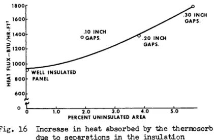
Fig. 16 shows some interesting results due to small uninsu- lated area. At f i r s t , these results seem unreasonable, but a comparison of the increase with the radiation potential of the hot heat shields shows that the results could be expected. The
curve shown is for a heat shield temperature of l800°F.
Fig. 17 shows the change in cold wall temperature as a function of steam chamber vent pressure. The cold wall i s warmer than saturation temperatures primarily because of heat
short effects.
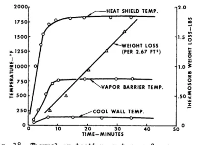
Finally, Fig. 18 shows a complete panel operating with a hot side temperature of 17hO°F — a temperature near the upper limit of the uncoated steel heat shields used for the particu- lar series of tests. The insulation was nominal 1/2 i n . thick, 6 lb/cu f t micro-quartz. The steam vent pressure was 1.6 psia.
The cold wall temperature was 135°F — only 17°F above the
saturation temperature of water at the same pressure.
The test does not represent a particular temperature-time p r o f i l e . Instead, the insulation thickness was arranged to give a vapor b a r r i e r temperature above 700°F, i . e . , near the upper value expected for any re-entry condition.
The stable cold wall temperature that follows the i n i t i a l transient is evidence of the cooling effect of the heat sink, and thus the proof-of-principle of the system concept i s demon- strated.
CONCLUSIONS
The following i s a l i s t of conclusions based upon the analy- s i s and test r e s u l t s : 1) the simplified methods of analysis described herein are adequate for preliminary design consider- ations, 2) the use of manufacturer's insulation material proper- t i e s w i l l provide adequate correlation between predicted and actual insulation performance, 3) additional heat sink weights required to compensate for structural heat shorts may best be established by testing the specific design concept, U) care should be taken to insure proper i n s t a l l a t i o n of insulation in a vehicle and packaging provided to insure that the insulation w i l l maintain i t s position during f l i g h t , and 5) f i n a l l y , the
a b i l i t y of the thermal protection concept described herein to provide adequate protection to crew or equipment has been demon-
strated.
heat transfer r a t e , Btu/hr-ft2
κ =
conductivity (Btu/hr) ( f t / f t ? oR) A = area, ft2Δ Τ = temperature difference, °R
Χ-
thickness, f tweight of heat sink, l b / f t2
θ = time, hr
Κ"
latent heat of vaporization, Btu/lbw
c = weight of insulation, l b / f t2w
s=
system weight ( Ww + w ^ )? = specific weight, l b s / f t 3 F e » radiative view factor T5- hot side temperature, °R
vapor b a r r i e r temperature, °R Tcw= cold w a l l temperature, °R
D = f l u i d flow f r i c t i o n factor (length)/diameter Mach number
NOMENCLATURE
H I G H W A T E R
F i g . 1 Thermosorb heat sink schematic
• 2 Thermosorb thermal p r o t e c t i o n system schematic
2 . 5
I N S U L A T I O N T H I C K N E S S - I N C H E S
Fig. 3 Thermal protection system weight optimization
T I M E — M I N U T E S
Fig. U Transient and simplified temperature p r o f i l e s for various re-entry missions
1 5 C A L C U L A T I O N S B A S E D O N T s - 3 2 0 0 ° R T e w = 5 4 0 ° R θ = 1 H O U R S Y S T E M W E I G H T / H f g = 1 0 5 0 B T U / L B
21 0" \ \ K p = 5 0 / / χ
I \ \ > — W A T E R Ú \ \ yy H E A T S I N K W E I G H T
=
TTA L- ^ H A V ^ V l N S U L A T . O N W E I G H T - . K p - 0 . 5 0 \ / F O R K p = 5 5V ^b// I N S U L A T I O N W E I G H T
^ ^ N f ^ F O R K p - 0 . 5 0
J ff - ^ ^ ^ ^ ^ ^
0 9 1 0 0 0 1 5 0 0 2 0 0 0 1 V A P O R B A R R I E R T E M P E R A T U R E — ° F
F i g . 5 Optimum system weight v a r i a t i o n with i n s u l a t i o n c o n d u c t i v i t y and density
2 °°[ ^ ^ ^ ^ ^ ^ ^ P CF A-1 0 0
Η. R E F R A S I L
S 1 5 0 - — 3 5 PF CA'1 0 0 R E FL R A S ,
º S^^^^^ P C F M I C R O - O U A R T Z
ULI
£ . 5 0 •
Ol 1 . . . « .
0 2 0 4 0 6 0 8 0 1 0 0 1 2 0 M I S S I O N H E A T F L U X x l O "3 B T U / F T2
F i g . 6 E f f e c t o f i n s u l a t i o n type on thermal p r o t e c t i o n system weight
F e . 9 0
1 8 0 "
ΞZ ^ · . 1 0
\ CO CD 1 . 6 0 -
I
»— X ο
2 1 4 0 -
=*
S LU
£ 1 . 2 0 -
>- λ
° 0 5 0 1 0 0 1 5 0 2 0 0 C O O L W A L L T E M P E R A T U R E - ° F
F i g . 7 V a r i a t i o n i n optimum system weight with r a d i a t i v e view f a c t o r . Lunar mission p r o f i l e using 6 l b / f t ^ micro-quartz i n s u l a t i o n
* 8 0 0 r \
wu
< 6 0 0 -
£ — C O O L W A L L T E M P = 2 1 2 ° F
* - 4 0 0 - \ ^ — -
* I \
o_ ' 6 ~ j _ + j _ _ I ^ C O O L W A L L T E M P . = 5 0 ° F
< « Α Λ ^ " 6 t ω 2 0 0 -
oc Ï α.
> φl . . , , ,
0 . 2 0 . 4 0 . 6 0 . 8 0 1.0 R A D I A T I V E V I E W F A C T O R - F e
F i g . 8 E f f e c t o f r a d i a t i v e view f a c t o r on vapor b a r r i e r temperature
ο» . . . 1 . . Ο 2 0 4 0 6 0 8 0 1 0 0 1 2 0
I L / D
F i g . 9 Variation in pressure ratio with mach number and fL/D
.15,
LU X
Ο I CS » 1 1 - τ = ^ — ^ ~ -,
0 5 0 7 5 1 0 0 1 2 5 1 5 0
T H E R M O S O R B B O I L I N G T E M P E R A T U R E - ° F
F i g . 10 Vent clearance requirements
.14r
T H E R M O S O R B B O I L I N G T E M P E R A T U R E - ° F
Fig. 11 Valve throat area requirements
Fig. 1 2 Heat absorbed by thermosorb. Solid l i n e s represent calculated values
/-4.B8 PCF A-100 / R E F R A S I L
3.17 P C F - - J
M I C R O - O U A R T Z /
3 " ^ ^ - 4 . 4 2 PCF
\ M I C R O - O U A R T Z 3.13 PCF M I C R O - O U A R T Z - * ^-3.17 PCF
M I C R O - O U A R T Z Ο T E S T DATA
D E N S I T Y V A L U E S A R E AS I N S T A L L E D I N T E S T P A N E L
1 1 1
1.0 2.0 3.0
K f > - ( B T U - I N / F T2- H R -
4 . 0
°F)(PCF)
5.0
F i g . 13 Correlation of t e s t and published values of insulation
J 1.41
LU
û 1 2
LU t—
ô i.o|
LU oc
% .80|
UJ _ ~
•— 0
Ο T E S T DATA
o
4 0 0 5 0 0 6 0 0 7 0 0 8 0 0 P R E D I C T E D V A P O R B A R R I E R T E M P E R A T U R E - ° F
F i g . Iii Correlation of t e s t and calculated vapor b a r r i e r temperatures
O T E S T D A T A - T R U S S CORE PANEL
x 0 0 ^ 40Ö 50Ö" 6 0 0 7 0 0 8 0 0
V A P O R B A R R I E R T E M P E R A T U R E — ° F
Fig. 15 Heat short penalty due to structural supports
PERCENT U N I N S U L A T E D AREA
Fig. 16 Increase in heat absorbed by the thermosorb due to separations in the insulation
3 0 0 r
2 4 6 8 S T E A M C H A M B E R P R E S S U R E - P S I A
Fig. 17 Cooled structure temperature variation with vent chamber pressure
T I M E - M I N U T E S
Fig. 18 Thermal protection system performance under test conditions