https://doi.org/10.1007/s11468-020-01298-1
Spectral Engineering Via Complex Patterns of Circular Nano‑Object Miniarrays: II. Concave Patterns Tunable by Integrated Lithography Realized by Circularly Polarized Light
Emese Tóth1 · Áron Sipos2 · Olivér A. Fekete1 · Mária Csete1
Received: 8 April 2020 / Accepted: 13 October 2020
© The Author(s) 2020
Abstract
The use of circularly polarized beams in interferometric illumination of colloid sphere monolayers enables the direct fabri- cation of rectangular patterns composed of circular nanohole miniarrays in metal films. This paper presents a study on the spectral and near-field effects of complex rectangular patterns consisted of a central nanoring and slightly rotated satellite nanocrescents in azimuthal orientations, which promote coupling between localized and propagating plasmons. To inspect the localized modes separately, we investigate the spectral responses and near-field phenomena of hexagonal patterns com- posed of uniform nanorings and nanocrescents, which can be fabricated by a single, homogeneous, circularly polarized beam incident perpendicularly and obliquely, respectively. To understand the interaction of localized and propagating modes, we analyze artificial rectangular patterns composed of a singlet nanoring, a singlet horizontal nanocrescent, and a quadrumer of four slightly rotated nanocrescents. The results demonstrate that on the rectangular pattern of a singlet horizontal nanocres- cent the interacting C2 and C1 localized resonances in the C orientation ( 0◦ azimuthal angle) and the U localized resonance coupled with propagating surface plasmon polaritons (SPPs) in the U orientation ( 90◦ azimuthal angle) manifest themselves in similar split spectra. Moreover, split spectra appear due to the coupling of the azimuthal orientation independent localized resonance on the nanorings and the SPPs propagating on their rectangular pattern in the U orientation. The spectral response of the complex miniarray pattern can be precisely tuned by varying the geometrical parameters of the moderately interacting nanoholes and the pattern period. In appropriate configurations, the fluorescence of the dipolar emitters is enhanced, which has potential applications in bio-object detection.
Keywords Concave nano-object patterns · Fluorescence enhancement of dipolar emitters · Localized surface plasmon resonance · Nanoplasmonics · Spectral engineering · Surface plasmon polariton · Tunable near-field properties · Tunable spectral properties · Wood–Rayleigh anomaly
Introduction
Surface plasmons were rediscovered through the recognition of unique spectral and near-field properties of hole arrays in metal films [1–5]. Such concave patterns can act as
plasmonic crystals, and the resulting optical properties can be tuned by controlling the shape and size parameters of either the constituent nanoholes or the periodic pattern.
Depending on the size, shape, and relative orientation with respect to the direction of the electric field ( Ē-field) oscilla- tion, an individual nanohole in a metal film can spectrally modulate and significantly enhance the Ē-field [2, 4, 5].
Among the different possible geometries, C-shaped aper- tures are particularly interesting because they can result in an Ē-field enhancement by three orders of magnitude and a confinement down to a tenth of the wavelength, as first dem- onstrated in the microwave region [4, 6]. Extraordinary transmission can occur through arrays of sub-wavelength holes of various shapes [1–5]. The earliest studies of this phenomenon revealed that transmittance minima (maxima)
* Mária Csete
mcsete@physx.u-szeged.hu Áron Sipos
sipos.aron@brc.hu
1 Department of Optics and Quantum Electronics, University of Szeged, Szeged H-6720, Hungary
2 Institute of Biophysics, Biological Research Centre, Szeged H-6726, Hungary
/ Published online: 13 November 2020
design rules of plasmonic spectral engineering rely on the interplay between the Fabry Perot resonances localized inside individual nanoholes, resulting in broad spectral lines, and grating-coupled resonances on plasmonic lattices, resulting in narrow spectral lines [3–5]. In two-dimensional hole arrays, the periodicity in a certain direction is described by a lattice vector k̄ , and when the Ē-field projection is sig- nificant along k̄ , the parallelism promotes coupling between SPPs and the grating. In other words, narrow spectral fea- tures originating from higher-order Bragg resonances were identified on microscale rectangular arrays of nanoholes [12]. Furthermore, the interaction of coupled localized sur- face plasmon resonances (LSPRs) and SPPs was demon- strated to result in a complex and finely tunable spectral response [13]. Concave patterns in metal films have already various important applications. Coupled resonances result- ing in narrow Fano-lines are particularly beneficial in bio- sensing applications [14]. The polarization insensitivity of square arrays of spherical nanoholes enables the polarization entanglement to be preserved [15]. Moreover, elliptical holes arranged in pairs of sub-lattices enable polarization-induced frequency shifts [16]. The first metamaterials to achieve spectral effect close to the visible region were created by using rectangular arrays of sub-wavelength holes [17]. For example, C-shaped apertures were used to enhance the pho- tocurrent in Ge detectors at 1310 nm, with maximum effi- ciency obtained with the Ē-field direction parallel to the arms of the aperture [18]. Several examples prove that the widely tunable grating-coupled resonances, when using nanovoid and nanohole arrays, enable high sensitivity bio- sensing [19]. Combined spectral and near-field studies revealed that the transmittance minima (maxima) exhibit smaller (larger) sensitivity on hexagonal and square hole arrays [20–22]. Moreover, special individual scatterers such as hole doublets ensure enhanced sensitivity due to the antennas that appear at their apexes [4, 23]. In addition, transmittance peaks corresponding to Bragg resonances along the Ē-field direction produce considerably enhanced sensitivity for square arrays [24]. The high local-field
demonstrated [31, 32]. Complementary C-shaped split-ring resonators were proposed to design metasurfaces with poten- tial applications as frequency- and polarization-selective filters [33]. Directional coupling of SPPs was achieved by arrays of complementary C-shaped split-ring resonators, which facilitates the miniaturization of photonic and plas- monic circuits [34]. Babinet inverted plasmonic metasur- faces were used to produce spin-selective second-harmonic vortex beams [35]. It was shown that disks and cylindrical apertures differ quantitatively with respect to the Babinet complementarity because the apertures produce higher mag- netic-to-electric-field ratios and better charge-transfer prop- erties [36]. Miniarrays of elliptical nanoholes that are not superimposable on their mirror image exhibit chiroptical effects, i.e., selective reflection of a single spin state while preserving its handedness [37]. However, fabrication of non- hexagonal (e.g., rectangular) arrays of nano-objects was previously possible only by expensive and complex electron- beam lithography procedures [38]. Double-exposure, two- beam interference lithography has been applied to fabricate one-dimensional and two-dimensional structures in gold film (e.g., rectangular array of nanoholes) [39]. Colloid sphere lithography has been used to generate imprinted nanochan- nel alumina patterns with hexagonal symmetry [40]. Laser- based colloid sphere lithography can be used to fabricate nanoholes via colloid spheres, which can be isolated, aggre- gated and embedded into monolayers, and the parameters of the fabricated nanoholes depend on the size and material of the colloid spheres, on the environment and laser parameters [41]. Tilting during treatment makes it possible to fabricate sub-diffraction objects of arbitrary shape [42]. As an alterna- tive method, the combination of phase-shifting lithography, etching, electron-beam deposition, and lift-off procedure was developed and used to fabricate microscale periodic rectan- gular arrays of nanoscale holes [12]. Nanorings have been also prepared by biomolecule-assisted deposition of gold spheres into previously fabricated nanoholes [25]. To over- come the limitations of laser-based colloid sphere lithogra- phy, chemical treatments were applied to create Janus and
patchy colloids, template-based substrates were fabricated to ensure geometrical confinement, and electric as well as magnetic forces were applied to position colloid assemblies [43]. Multiscale periodic colloid assemblies were created by combining thermo-responsive depletion with pre-patterned surface features [44]. In our previous studies, we presented the interferometric illumination of colloid sphere monolay- ers (IICSM) that enables the independent tuning of numer- ous geometrical parameters [45, 46]. The method combines colloid sphere (CS) and interference lithography and syn- thesizes all the advantages of these methods, thus providing a good tool to fabricate versatile patterns. In our previous papers, we presented the IICSM method for illumination by linearly [45] and circularly [46] polarized light. In this paper, we present and discuss the spectral and near-field effects achievable by complex patterns of rounded nanoholes; more precisely, by miniarrays of nanorings and nanocrescents that form an ordered and pre-designed rectangular pattern. The rounded objects originate from illumination using circularly polarized beams and form miniarrays defined by the specific interferometric illumination configuration. For reference purposes, we also discuss spectral and near-field effects achievable by hexagonal patterns of nanorings and nanocres- cents that originate from the illumination of CS monolayers by a single, homogeneous perpendicularly and obliquely incident circularly polarized beam, respectively. The spectral and near-field effects of the building blocks arranged in rec- tangular patterns (i.e., a singlet nanoring, a singlet horizontal nanocrescent, and a quadrumer of slightly rotated satellite nanocrescents) are also analyzed. The potential of all these structures to enhance the fluorescence of dipolar emitters is also demonstrated. Part I of this paper describes the spectral and near-field effects of the analogous convex patterns [47].
Reference [46] presents a comparative study on the spectral and near-field effects of complementary concave and convex patterns, which can be directly fabricated via IICSM fol- lowed by a lift-off procedure. Finally, a detailed comparative study on the corresponding optical responses of complemen- tary patterns [i.e., the reflectance (transmittance) of the con- cave patterns and the transmittance (reflectance) of the con- vex patterns] will be presented in our upcoming paper [48].
Method
Numerical Modeling and Characterization of Patterns Composed of Concave Spherical Nano‑Objects
We used the radio frequency finite-element method (FEM) module of COMSOL Multiphysics software package (COMSOL AB, Sweden) to study the structures that can be fabricated by illumination using a single homogeneous
circularly polarized beam and by IICSM using two circu- larly polarized beams. In this study, d = 100-nm-diameter gold colloid spheres are arranged into a hexagonally close- packed monolayer on a 45-nm-thick gold-coated NBK7 substrate and are illuminated by a single homogeneous, perpendicularly or obliquely incident beam or by two obliquely incident interfering beams, which are 𝜆 = 400 nm and circularly polarized. The illumination of one unit cell of hexagonal gold CS monolayer was realized by using three-dimensional periodic models, which enabled the use of any desired azimuthal orientation and angle of inci- dence for a single beam as well as for multiple beams. All materials were modeled by taking into account the wave- length-dependent optical properties. More specifically, the NBK7 glass was qualified by using the Cauchy for- mula n=A+ B
𝜆2 + C
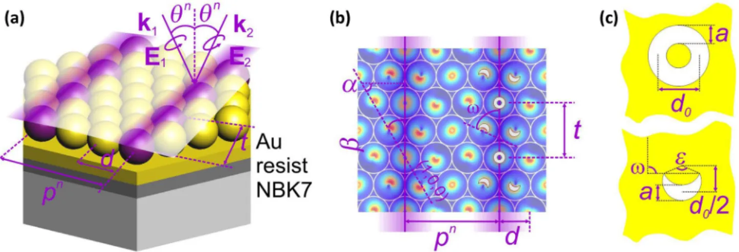
𝜆4 ( ANBK7=1.503 , BNBK7=4.395⋅103 , CNBK7=8.585⋅105 ) [49], whereas, for gold, tabulated data sets were interpolated to implement the wavelength- dependent dielectric properties [50]. The schematic draw- ing in Fig. 1a shows the IICSM concept for illumination by two circularly polarized beams. The required condition for the IICSM method is the perfect synchronization of a hexagonal close-packed CS monolayer and an illumi- nating interference pattern. Figure 1b and 1c shows the main characteristic geometrical parameters that can be varied via IICSM with a circularly polarized beam. In the so-called close-packed in-between array configuration, the pn periodicity can be tuned to pn=n⋅d∕2 discrete values, which are achievable at the angle of incidence 𝜃n =arcsin(𝜆∕(n⋅d)) , where d is the CSs diameter, and n≥1 is an integer. The angle 𝛼 identifies the orientation of the plane of incidence with respect to the (100) lattice direction of the hexagonal monolayer, and the resulting inter-object distance t varies with the corresponding ori- entation 𝛽 of the interference pattern. Figure 1b and 1c shows the complex interference pattern, and the resulting concave pattern in a gold layer, which is inspected in this work̄ , where t=√
3⋅d is the inter-object distance fabri- cated for 𝛽 = 3 0◦ . The parameters d0 and a determine the nano-object size and are tunable by adjusting the wave- length 𝜆 and the beam intensity, as well as by adjusting the CSs diameter d′ and its material. In the present study, d = d = 100 nm, which implies the assumption that the gold colloid spheres touch each other. This assumption is rea- sonable, since our previous studies showed that the nano- object parameters are not significantly modified when the diameter is reduced ( d′<d condition ensures a greater intensity at the substrate interface than at the monolayer central plane where the spheres touch each other). Both the nanoring and nanocrescent stem from the circular polari- zation of the beams, proving that the exact shape of the generated nanoholes is polarization dependent [45, 46].
Spectral and Near‑Field Study of Various Patterns The complete spectral study of 45-nm-thick gold films deco- rated by different nanohole patterns was realized, i.e., the effect of these complex patterns on the optical response and on the near-field distribution was determined. Floquet peri- odic boundary conditions were applied on vertical bounda- ries of the FEM (COMSOL) models, which composed of various hexagonal and rectangular unit cells exposed to p-polarized plane-wave post-illumination. The inspected realistic hexagonal patterns are as follows: a hexagonal pat- tern of (i) nanoring-shaped holes (Figs. 2a, 3a, 3b, 3d), and (ii) horizontal nanocrescent-shaped holes (Figs. 2b, 3, 3c, 3e;
vertical nanocrescents are presented in the Supplementary Material). The nanoholes are called nanorings and nano- crescents for the sake of simplicity. The studied artificial composing rectangular patterns are as follows: a 300 nm rec- tangular pattern of (iii) a singlet nanoring (Fig. 4), (iv) a sin- glet horizontal nanocrescent (Fig. 5), and (v) a quadrumer of slightly rotated nanocrescents (Fig. 6). Finally, two different rectangular patterns were analyzed: a (vi) 300 nm (Figs. 2c, 7) and (vii) 600 nm periodic (Figs. 2d, 8) rectangular pattern of the same miniarray consisted of a central nanoring and a quadrumer of slightly rotated nanocrescents. In this spectral study, p-polarized light with incidence plane oriented at 𝛾 azimuthal angle (that is measured with respect to the y axis in the insets of Figs 3-8) illuminated the perforated gold film in a symmetric environment, meaning that the film was sur- rounded by NBK7 glass and the nanoholes were filled with the same material. To uncover the characteristic LSPRs sup- ported by the nanoholes without grating-coupling to either the photonic or plasmonic modes, the hexagonal pattern of concave nanorings and nanocrescents were inspected in 0◦
and 90◦ azimuthal orientations. For rectangular patterns, both the 90◦ ( 106◦ ) and 0◦ ( 16◦ ) azimuthal orientations were inspected, since these promote LSPR as well as grating-cou- pling effects in the case of horizontal nanocrescents (LSPR in the case of the quadrumers and miniarrays). Following the nomenclature introduced for convex nanocrescents and taking into account the complementarity according to the Babinet principle, the LSPR of nanocrescent-shaped holes is called the C (U) resonance when the Ē-field oscillates parallel (perpendicular) to their symmetry axis [33, 35, 36, 51]. Accordingly, in (close to) the C and U orientation refers to the illumination configuration, when the incidence plane of p-polarized light is at 0◦ ( 16◦ ) and 90◦ ( 106◦ ) azimuthal angle, and the Ē-field oscillates perfectly (almost) parallel and perpendicular to the symmetry axis of horizontal singlet concave nanocrescents in Figs. 3 and 5. Similarly, in (close to) the C and U orientation refers to the illumination configu- ration, when the incidence plane of p-polarized light is at 16◦ ( 0◦ ) and 106◦ ( 90◦ ) azimuthal angle and the Ē-field oscillates perfectly (almost) parallel and perpendicular to the symme- try axis of slightly rotated nanocrescents in quadrumers and miniarrays in Figs 6-8. Further details are provided in Refs.
[46–48]. The spectra were taken over the range 200-1000 nm with 10 nm resolution and at 𝜑 = 0◦ polar angle (i.e., at per- pendicular incidence; see Figs. 3-8a). FEM (COMSOL) was used to inspect the dispersion characteristics of the concave patterns by selecting fractions on the high-symmetry path throughout their irreducible Brillouin zone according to the azimuthal orientations that facilitate detection of the LSPR on composing circular nano-objects and mapping of the cou- pled SPP branches. Accordingly, the dispersion characteris- tics were analyzed for the 0◦ and 90◦ azimuthal orientations.
To compute the dispersion diagram, the spectral range was
Fig. 1 Schematic drawings showing characteristic size parameters:
(a) three-dimensional scheme of periodic pattern fabrication by interferometric illumination of d diameter CS, where 𝜃n polar angle defines the pn pattern period (b) 𝛼 orientation of the plane of inci-
dence defines the 𝛽 orientation of the resulting interference pattern, which is used to tune the distance t between nano-objects, (c) gener- ated features qualified by the central diameter d0 , the central thickness a, the opening angle 𝜀 , and the nano-object orientation 𝜔
extended through 1000 nm with the same 10 nm wavelength resolution, as for perpendicular incidence, whereas the 𝜑 angle of incidence was modified from 0◦ to 85◦ in 5◦ steps (Figs. 3d, 3e, and 4-8c). To uncover all underlying modes on the dispersion graphs, higher-resolution complementary calculations were realized in smaller steps wherever needed.
According to the literature, the absorptance spectra of plas- monic patterns are very useful to find resonances, so herein the absorptance spectra and dispersion characteristics are analyzed [52]. To separate the effect of complex plasmonic structures from the background of the continuous gold film, the spectra were rectified. Specifically, first the optical signal of a solid gold film of the same thickness as the perforated film was subtracted, then the absorptance values were nor- malized by multiplying the spectra by the ratio of unit-cell area to nanohole area (Figs. 3-8a). The near-field distribu- tion and charge distribution were inspected by taking into
account the complementarity of the modal profiles according to the Babinet principle [33, 35, 36]. Specifically, the com- plementarity of the time-averaged Ez distribution on convex patterns corresponding to the time-averaged Bz distribution on concave patterns allows us to determine the accompa- nying time-averaged Ez distribution and the characteristic charge distribution at the C and U resonances on patterns composed of concave nanocrescents (Figs. 3b, 3c, and 4-8b) [46–48, 51]. Localized plasmon resonances on the nanorings and nanocrescents are distinguished by using r and c in the abbreviations. First- and second-order grating-coupled SPPs are denoted "SPP1" and "SPP2", respectively. The FEM was used to inspect the capabilities of the artificial patterns to enhance fluorescence, namely the rectangular patterns of a singlet nanoring and a quadrumer of nanocrescents, as well as of the rectangular patterns of their miniarray (Fig. 9).
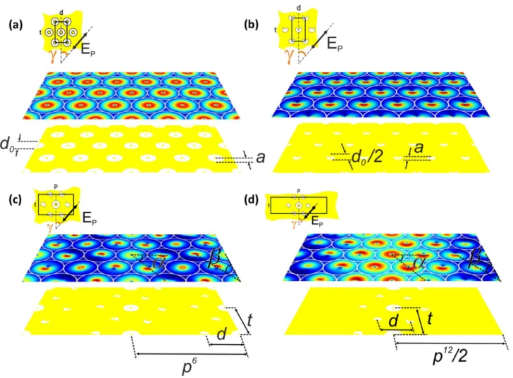
Fig. 2 Normalized Ē-field distribution under gold CS monolayers illuminated by single circularly polarized beam incident (a) perpen- dicularly and (b) obliquely, which results in a hexagonal pattern of nanoholes, and (c), (d) by two interfering beams (in 𝛽=30◦ orienta- tion with respect to the (100) plane of the original CS monolayer) in
IICSM configuration, which results in a rectangular pattern of miniar- rays. The insets show the unit cells of the complex patterns: a hex- agonal pattern of (a) nanorings and (b) nanocrescents, and a rectangu- lar pattern of miniarrays consisted of a central nanoring and satellite nanocrescents with (c) p6 = 300 nm and (d) p12 = 600 nm periodicity
Results and Discussion
Patterns Achievable in Different Illumination Configurations
To determine the patterns achievable by homogeneous illu- mination and by IICSM, the Ē-field distribution was exam- ined at the surface of gold films. The d0 and a parameters were calculated based on the full width at half maximum of the intensity distribution. Illumination by a single, homoge- neous, perpendicularly incident, circularly polarized beam results in (i) a hexagonal pattern of uniform nanorings with 10 nm and 46 nm inner and outer diameters, respectively (Fig. 2a). A single, homogeneous, obliquely incident, cir- cularly polarized beam generates (ii) a hexagonal pattern of uniform nanocrescents; Fig. 2b shows the case for the angle of incidence 𝜃6 =41.8◦ . The nanocrescents were approxi- mated as the intersections of two cylindrical objects of 25 nm and 20 nm diameter separated by 12.5 nm between their centers. Figure 2c and 2d illustrates the effect of modifying the periodicity of the interference pattern in IICSM. Namely, (vi) a rectangular pattern with p6 = 300 nm periodicity appears at 𝜃6=41.8◦ angle of incidence, which corresponds to the case n = 6, whereas (vii) a rectangular pattern with p12 = 600 nm develops at 𝜃12=19.5◦ angle of incidence, which corresponds to the case n = 12. Taking into account
that the nano-object size parameters d0 and a are tunable by adjusting the intensity and to simplify the comparison between miniarrays with different periodicities, analogous nanohole parameters were assumed during the spectral and near-field study of both rectangular patterns, as shown in the insets of Fig. 2. Specifically, the inner and outer central nanorings have diameters of 10 nm and 50 nm, while the satellite nanocrescents have the same size parameters as in the hexagonal array (Figs. 2c and 2d).
Spectral and Near‑Field Effects of Different Patterns The common property of the rectified absorptance extracted from concave patterns is that the fingerprints of the spec- trally overlapping and interacting particle plasmon reso- nance (PPR) and c-C2 resonance in the C orientation, as well as the PPR signatures in the U orientation are miss- ing. This is caused by the subtraction of the continuous film absorptance, which exhibits commensurate enhancement in the spectral interval of the PPR [47, 48]. The Babinet principle predicts that the Ez distribution on the comple- mentary convex pattern corresponds to the Bz distribution on the concave pattern, and the accompanying Ez distribution on the concave pattern reveals the charge distribution at the characteristic resonances [33, 35, 36, 47, 48].
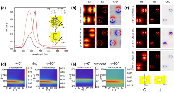
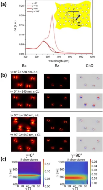
Fig. 3 Hexagonal patterns composed of concave nanorings and hori- zontal nanocrescents: (a) absorptance spectra; Bz and Ez and charge (ChD) distribution in (top) 0◦ and (bottom) 90◦ azimuthal orienta- tion of (b) nanorings and (c) nanocrescents; dispersion characteris-
tics computed for (left) 0◦ and (right) 90◦ azimuthal orientation of (d) nanorings and (e) nanocrescents. Insets show schematic drawing of the unit cells presenting the C and U configurations of horizontal con- cave nanocrescents
Hexagonal Pattern of Concave Nanorings
Given the spherical symmetry of the constituent nano- objects and the symmetries of the hexagonal lattice, a single maximum appears at 570 nm in the rectified absorptance of the hexagonal pattern composed of con- cave nanorings azimuthal orientation independently (Fig. 3a). Moreover, the global maxima overlap com- pletely in the 90◦ and 0◦ azimuthal orientations. The Bz distribution reveals lobes both on the inner and outer rim of the concave nanorings, perpendicular to the Ē -field direction, which corresponds to the lobes of the Ez distribution on the complementary hexagonal pattern of
convex nanorings [47, 48]. In contrast, the accompany- ing Ez distribution indicates lobes parallel to the Ē-field direction on the concave nanorings, which reveals the characteristic charge distribution composed of reversed dipoles on the inner and outer rim of the nanorings at the indistinguishable r-C and r-U resonance (Fig. 3b, top and
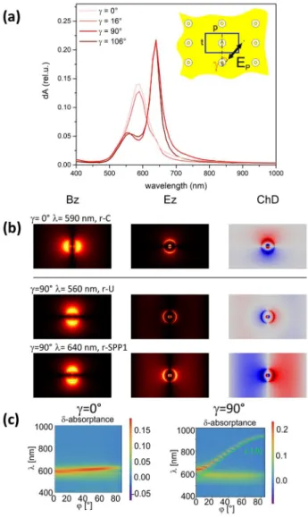
Fig. 4 Rectangular p6 = 300 nm periodic pattern composed of a singlet concave nanoring: (a) absorptance spectra; (b) Bz and Ez and charge (ChD) distribution in (top) 0◦ and 16◦ and (bottom) 90◦ and 106◦ azimuthal orientation; (c) dispersion characteristics com- puted for (left) 0◦ and (right) 90◦ azimuthal orientation. Inset shows schematic drawing of the unit cell. Note that clicking on the figure switches between 0◦ and 16◦ and between 90◦ and 106◦ azimuthal ori- entations
Fig. 5 Rectangular p6 = 300 nm periodic pattern composed of a hori- zontal singlet concave nanocrescent: (a) absorptance spectra, (b) Bz , Ez , and charge (ChD) distribution in (top) 0◦ and 16◦ and (bottom) 90◦ and 106◦ azimuthal orientation, (c) dispersion characteristics com- puted for (left) 0◦ and (right) 90◦ azimuthal orientation. Inset shows schematic drawing of the unit cell. Note that clicking on the figure switches between 0◦ and 16◦ and between 90◦ and 106◦ azimuthal ori- entations
bottom). The azimuthal orientation independent r-C and r-U LSPRs on the nanoring result in a single flat band in the dispersion characteristics (Fig. 3d).
Hexagonal Pattern of Horizontal Concave Nanocrescents Hexagonal Pattern of Horizontal Concave Nanocrescents in the C Orientation In the rectified absorbance of the hex- agonal array composed of horizontal concave nanocrescents,
a shoulder at 580 nm is followed by a global maximum at 640 nm in the C orientation ( 0◦ azimuthal angle) (Fig. 3a).
On the Bz distribution, the four neighboring c-C2 resonance- related and the two c-C1 resonance-related lobes result in two well-separated composite lobes at the shoulder. This is accompanied by three bright and three weak lobes on the Ez distribution on the small and large arch of the nanocrescents,
Fig. 6 Rectangular p6 = 300 nm periodic pattern composed of a quadrumer of concave nanocrescents: (a) absorptance spectra, (b) Bz , Ez and charge (ChD) distribution in (top) 16◦ ( 0◦ ) and (bottom) 106◦ ( 90◦ ) azimuthal orientation, (c) dispersion characteristics com-
puted for (left) 0◦ and (right) 90◦ azimuthal orientation. Insets show schematic drawing of the unit cell. Note that clicking on the figure switches between 0◦ and 16◦ and between 90◦ and 106◦ azimuthal ori- entations
Fig. 7 Rectangular p6 = 300 nm periodic pattern composed of a complex concave miniarray: (a) absorptance spectra, (b) Bz , Ez , and charge (ChD) distribution in (top) 16◦ ( 0◦ ) and (bottom) 106◦ ( 90◦ ) azimuthal orientation, (c) dispersion characteristics computed for 0◦
(left) and 90◦ (right) azimuthal orientation. Inset shows a schematic drawing of the unit cell. Note that clicking on the figure switches between 0◦ and 16◦ and between 90◦ and 106◦ azimuthal orientations
Fig. 8 Rectangular p12 = 600 nm periodic pattern composed of a complex concave miniar- ray: (a) absorptance spectra, (b) Bz , Ez , and charge (ChD) distribution in (top) 16◦ ( 0◦ ) and (bottom) 106◦ ( 90◦ ) azimuthal orientation, (c) dispersion characteristics computed for 0◦
(left) and 90◦ (right) azimuthal orientation. The insets show schematic drawings of the unit cell. Note that clicking on the figure switches between 0◦ and 16◦ as well as between 90◦ and 106◦ azimuthal orientations
on the arches of the nanocrescents, with the significantly stronger lobe on the smaller arch. The characteristic charge distribution is dipolar along the Ē-field direction at the c-C1 resonance (Fig. 3c, top). The interacting c-C2 and c-C1 LSPRs on the horizontal nanocrescent result in two overlap- ping flat bands in the dispersion characteristics (Fig. 3e, left).
Hexagonal Pattern of Horizontal Concave Nanocres‑
cents in the U Orientation In comparison, in the rectified absorptance of the hexagonal pattern composed of hori- zontal concave nanocrescents, only the global maximum appears (at 570 nm) in the U orientation ( 90◦ azimuthal angle) (Fig. 3a). Two Bz lobes appear at the global maxi- mum: one on the large arch and the other distributed on the tips, which is accompanied by four lobes on the Ez distribu- tion on the nanocrescents. The characteristic charge distri- bution is quadrupolar and governed by the Ē-field direction at the c-U resonance (Fig. 3c, bottom). The c-U LSPR on the horizontal nanocrescent results in a single wide band in the dispersion characteristics (Fig. 3e, right).
Rectangular 300 nm Periodic Pattern of a Singlet Concave Nanoring
Rectangular 300 nm Periodic Pattern of a Singlet Concave Nanoring in the C Orientation of Nanocrescents When a singlet concave nanoring similar to those inspected in a (i) hexagonal pattern is arranged into a 300 nm periodic rec- tangular pattern, in the rectified absorptance there appears a global maximum (at 590 nm) in the C orientation of hori- zontal singlet (slightly rotated quadrumer concave nano- crescents) ( 0◦ ( 16◦ ) azimuthal angle)) and is followed by a tiny shoulder at 640 nm in the 16◦ azimuthal orientation (Fig. 4a). The Bz ( Ez ) distribution exhibits lobes perpendicu- lar (parallel) to the Ē-field direction at the global maximum.
Accordingly, the characteristic charge distribution at the r-C resonance consists of reversed dipoles on the inner and outer rims of the nanoring along the Ē-field direction. Given the spherical symmetry of the concave singlet nanorings,
tern. However, instead of a horizontal cross-coupled r-U mode, the reversed dipoles rotate on the nanoring (Fig. 4b, top). The r-C LSPR on the singlet nanoring results in a sin- gle flat band in the dispersion characteristics (Fig. 4c, left).
Rectangular 300 nm Periodic Pattern of a Singlet Concave Nanoring In The U Orientation of Nanocrescents In compari- son, in the rectified absorptance of the 300 nm periodic rec- tangular array composed of a singlet concave nanoring, the local maximum appearing at a slightly reduced wavelength of 560 nm is followed by a global maximum at 640 nm in the U orientation of horizontal singlet nanocrescent (slightly rotated quadrumer concave nanocrescents) ( 90◦ ( 106◦ ) azi- muthal angle) (Fig. 4a). At the local maximum, the Bz ( Ez ) lobes are perpendicular (parallel) to the Ē-field direction.
Accordingly, the characteristic charge distribution at the r-U resonance consists of reversed dipoles on the inner and outer rims of the concave singlet nanorings along the Ē-field direc- tion. In contrast, at the global maximum both for 90◦ and 106◦ azimuthal orientations, the Bz ( Ez ) field lobes are completely perpendicular (parallel) to the k̄p lattice vector. As a result, the Bz ( Ez ) lobes are rotated clockwise to a lesser extent compared with the local maximum in 106◦ azimuthal orientation. This indicates that the grating-coupling effect dominates with a strength correlated with the Ē-field component along the k̄p direction. Accordingly, at the global maximum, the horizontal reversed dipoles and the strong periodic charge modulation along the k̄p lattice vector demonstrate the grating-coupling of SPP1 modes of the (1, 0) order, which are more (less) pro- nounced in the 90◦ ( 106◦ ) azimuthal orientation (Figs. 4b, bot- tom and 4c, right). The interacting r-U LSPR on the singlet nanoring and the SPP1 on the pattern results in anticrossing bands in the dispersion characteristics (Fig. 4c, right).
Rectangular 300 nm Periodic Pattern of a Horizontal Singlet Concave Nanocrescent
Rectangular 300 nm Periodic Pattern of a Horizontal Sin‑
glet Concave Nanocrescent in the C Orientation When a
singlet horizontal concave nanocrescent is arranged into a 300 nm periodic rectangular array, only a shoulder appears in the rectified absorptance at 590 nm (580 nm) before the global maximum at 640 nm in (close to) the C orientation ( 0◦ ( 16◦ ) azimuthal angle) (Fig. 5a). On the Bz distribution, the four nearest-neighbor c-C2 resonance-related lobes and the two c-C1 resonance-related lobes result in four lobes at the shoulder, with maximum intensity at the nanocrescent tips. This is accompanied by two Ez lobes, with the stronger one appearing on the smaller arch of the nanocrescents. A quadrupolar and hexapolar charge distribution also appears in a noticeable fraction within one cycle of the time-depend- ent charge distribution. In contrast, at the global maximum, the two tips are coincident with the maxima on the Bz dis- tribution, whereas the accompanying Ez distribution indi- cates two lobes on the two arches of the nanocrescents: the stronger lobe appears on the smaller arch for both 0◦ and 16◦ azimuthal orientations. Thus, on the singlet concave nanocrescent in 0◦ azimuthal orientation, the characteristic charge distribution is dipolar along the Ē-field direction at the c-C1 resonance (Fig. 5b, top). The weakly interacting c-C2 and c-C1 LSPRs on the horizontal singlet nanocres- cent result in two overlapping flat bands in the dispersion characteristics (Fig. 5c, left).
Rectangular 300 nm Periodic Pattern of a Horizontal Singlet Concave Nanocrescent in the U Orientation In compari- son, for the rectified absorptance of the 300 nm periodic rectangular array composed of concave nanocrescents, a local maximum at 560 nm (570 nm) appears before the global maximum at 610 nm in (close to) the U orientation ( 90◦ ( 106◦ ) azimuthal angle). In addition to this, a shoul- der appears at 640 nm in the 106◦ azimuthal orientation (Fig. 5a). Two Bz lobes appear on the arches of the nano- crescents at the local maximum, with the stronger lobe appearing on the larger arch. This is accompanied by four Ez lobes on the nanocrescent. Accordingly, a quadrupolar charge distribution is characteristic at the c-U resonance on the horizontal singlet concave nanocrescent (Fig. 5b, bot- tom). In contrast, at the global maximum two lobes appear on the Bz distribution, the lobe on the tip becomes intense to the same degree as the lobe on the larger arch (the bridge between the tips disappears), whereas the accompanying Ez distribution still has four lobes, although two of these lobes have larger intensity on the smaller arch close to the nano- crescent tips. The characteristic charge distribution is still quadrupolar. In addition to this, a strong (weak) periodic charge modulation appears, which originates from grating- coupling of the order (1, 0) SPP1 modes. This reveals that SPPs are more (less) efficiently coupled when the Ē-field oscillates along (almost parallel to) k̄p in the 90◦ ( 106◦ ) azi- muthal orientation (Fig. 5b, bottom and 5c, right). At the shoulder, and appearing exclusively in the 106◦ azimuthal
orientation, two Bz lobes are apparent, distributed asym- metrically on the crescent tips. This is accompanied by two lobes on the Ez distribution on the nanocrescent arches, with larger intensity on the small arch. The dominant charge distribution indicates the dipolar c-C1 resonance, which is cross-coupled because of the Ē-field component along the symmetry axis of the nanocrescent (Fig. 5b, bottom).
The spectrum for the 106◦ azimuthal orientation is unique because the c-U resonance (at 570 nm) is followed by a peak caused by SPP1 grating-coupling at 610 nm, then a shoulder appears at 640 nm originating from the cross-coupled c-C1 resonance (Fig. 5c, right). The interacting c-U LSPR on the singlet horizontal nanocrescent and the SPP1 on the pattern result in anticrossing bands in the dispersion characteristics (Fig. 5c, right).
Rectangular 300 nm Periodic Pattern of a Quadrumer of Concave Nanocrescents
Rectangular 300 nm Periodic Pattern of a Quadrumer of Concave Nanocrescents in the C Orientation When a 300 nm rectangular pattern is composed of four slightly rotated concave nanocrescents, a shoulder appears in the rectified absorptance at 580 nm before the global maximum at 640 nm close to (in) the C orientation(0◦ ( 16◦ ) azimuthal angle) of the quadrumers (Fig. 6a). In contrast with the convex quadrumer counterpart, for concave patterns no such differ- ence exists between the extrema as observed in the pres- ence of either one or four nanocrescents [47, 48]. The field distributions are analogous with those observable on singlet nanocrescents. Specifically, the coalescence of four c-C2 resonance-related lobes and two c-C1 resonance-related lobes causes the Bz to exhibit four lobes at the shoulder, resulting in intensity maxima on the crescent tips. This is accompanied by two Ez lobes on the nanocrescent arches, with the stronger lobe appearing on the smaller arch. The charge distribution is mainly quadrupolar (i.e., no hexapolar modulation is apparent), in contrast with the horizontal sin- glet-nanocrescent case. At the global maximum, two lobes on the Bz distribution show intensity maxima on the nano- crescent tips, whereas the accompanying Ez distribution reveals two lobes on the arches of the nanocrescents, with the lobe on the smaller arch being significantly stronger.
The characteristic charge distribution is dipolar along the Ē-field direction at the c-C1 resonance of the quadrumer of four nanocrescents in the 16◦ azimuthal orientation (Fig. 6b, top). The strongly interacting c-C2 and c-C1 LSPRs on the quadrumer result in two slightly separated flat bands in the dispersion characteristics (Fig. 6c, left).
Rectangular 300 nm Periodic Pattern of a Quadrumer of Con‑
cave Nanocrescents in the U Orientation In comparison, the global maximum at 560 nm in the rectified absorptance of
nanocrescent axis. Accordingly, a quadrupolar charge dis- tribution develops at the c-U resonance on the quadrumer of four nanocrescents in 106◦ azimuthal orientation (Fig. 6b, bottom). In contrast, at the shoulder appearing exclusively in the 90◦ azimuthal orientation, the Bz distribution has two lobes on the crescent tips (larger arch) that become more (less) intense, whereas the Ez distribution indicates only two lobes, with the lobe on the small arch of the nanocrescents becoming more intense. The characteristic charge distribu- tion is dipolar and, as a result, the quadrumer of nanocres- cents has a net dipole moment. Comparison with the charge distribution of the C orientation at the same spectral posi- tion reveals that a dipolar charge distribution appears, analo- gous with that of the c-C1 charge distribution. This is due to the Ē-field component lying along the symmetry axes of the concave nanocrescents, which enables cross-coupling of the c-C1 resonance in the 90◦ azimuthal orientation (Fig. 6b, bottom). Surprisingly, no SPP1 coupling is caused by the group symmetry of the quadrumer (Fig. 6c, right). The c-U LSPR on the quadrumer of nanocrescents results in a single horizontal band in the dispersion characteristics (Fig. 6c, right).
Rectangular 300 nm Periodic Pattern of a Complex Concave Miniarray
Rectangular 300 nm Periodic Pattern of a Complex Con‑
cave Miniarray in the C Orientation When a 300 nm peri- odic rectangular pattern is composed of a complex con- cave miniarray consisted of both the central nanoring and quadrumer of nanocrescents, a local maximum appears in their absorbance at 590 nm before the global maximum at 640 nm close to (in) the C orientation ( 0◦ ( 16◦ ) azimuthal angle) (Fig. 7a). Only a slight difference occurs between the local and global maximum of the complex miniarray and the global maximum (shoulder) and shoulder in 16◦ azimuthal orientation (global maximum) in the case of a singlet nanoring (quadrumer of four nanocrescents). At the
tion but also a hexapolar charge modulation is observable that is similar to the singlet nanocrescent but contrasts with the case of the quadrumer nanocrescent (Fig. 7b, top). In contrast, at the global maximum, the nanoring exhibits significantly weaker lobes that appear exclusively on the outer rim, whereas the two lobes localized on the nano- crescent tips show asymmetrical (symmetrical) maxima on the Bz distribution. Accordingly, the accompanying Ez distribution has weak lobes of less well-defined directivity on the nanoring, whereas two significantly stronger lobes appear on the arches of the nanocrescents, especially on the smaller arch.
A dipolar charge distribution develops along the Ē-field direction on the nanocrescents and exhibits a pure c-C1 resonance on the quadrumer of nanocrescents in the 16◦ azi- muthal orientation, whereas weak reversed dipoles rotate on the nanoring instead of the expected horizontal cross- coupled r-U mode. The local maximum on the miniarray originates from the r-C resonance of the nanoring, which overlaps with the interacting c-C2 and c-C1 modes of the nanocrescents on the quadrumer; the latter also results in a shoulder in their spectrum. The global maximum origi- nates mainly from the c-C1 mode on the quadrumer of nano- crescents. At the global maximum, the cross-coupled r-U resonance on the nanoring spectrally overlaps with the c-C1 resonance on the nanocrescents. The intermittent perpen- dicularity of the weak rotating nanoring dipole and strong nanocrescent dipoles results in a Fano interference between the two LSPRs (Fig. 7b, top and 7c, left). The r-C resonance on the nanoring and the interacting c-C2 and c-C1 LSPRs on the quadrumer result in two separated flat bands in the dispersion characteristics (Fig. 7c, left).
Rectangular 300 nm Periodic Pattern of a Complex Con‑
cave Miniarray in the U Orientation In comparison, the local maximum at 560 nm in the rectified absorptance of the 300 nm periodic rectangular array composed of a com- plex concave miniarray the local maximum (560 nm/560 nm) is followed by a narrower global maximum at 640 nm
close to (in) the U orientation ( 90◦ ( 106◦ ) azimuthal angle) (Fig. 7a). The most important difference with respect to the nanocrescent quadrumer is the recovery of the sec- ond maximum, which has been observed already in the case of the singlet nanoring and singlet nanocrescent con- taining unit cells in the 90◦ azimuthal orientation. The Bz distribution exhibits strong lobes on the outer rim of the nanoring oriented perpendicularly to the Ē-field direction, with two lobes on the nanocrescents at the local maxi- mum. The stronger lobe appears on the larger arch of the nanocrescents, whereas the weaker lobe is asymmetri- cally (symmetrically) distributed on the nanocrescent tips in the 90◦ ( 106◦ ) azimuthal orientation. This is accompa- nied by the Ez distribution, indicating lobes along the Ē -field direction on the inner and outer rim of the nanoring, and four lobes asymmetrically (symmetrically) aligned on the nanocrescents. Accordingly, reversed dipoles arise on the inner and outer rim of the nanoring along the Ē -field direction at the r-U resonance, and a quadrupolar charge distribution appears on the nanocrescents at the c-U resonance (Fig. 7b, bottom). In contrast, at the global maximum the two lobes on the Bz distribution on the outer rim of the nanoring are aligned perpendicularly to k̄p for both the 90◦ and 106◦ azimuthal orientations, whereas the asymmetrically distributed lobes on the crescent tips show higher intensity than the lobe on the larger arch of the nanocrescents. However, the contribution of the quad- rumer nanocrescents is not significant at this extremum, as shown in Fig. 7b (bottom). The accompanying Ez dis- tribution indicates two lobes on the nanoring almost along the k̄p vector, and two asymmetrical lobes on the small arch of the nanocrescents that are more intense. The char- acteristic charge distribution includes a reversed dipolar distribution on the inner and outer rim on the nanoring along (slightly rotated with respect to) the k̄p vector and a weak quadrupolar distribution on the nanocrescents. The extended periodic charge modulation corresponds to the grating-coupled, (-1,0) order SPP1 ( k̄p≈k̄spp ). The mini- array local maximum originates from the sum of the coin- cident r-U mode of the nanoring and the c-U modes on the quadrumer of nanocrescents, whereas the grating-cou- pled SPP1 is responsible for the narrow global maximum (Figs. 7b, bottom and 7c, right). The r-U LSPR on the nanoring overlaps with the c-U LSPRs on the quadrumer of nanocrescents and couples with the SPP1 on the rectan- gular ring pattern, which results in anticrossing bands in the dispersion characteristics (Fig. 7c, right).
Rectangular 600 nm Periodic Pattern of a Complex Concave Miniarray
Rectangular 600 nm Periodic Pattern of a Complex Concave Miniarray in the C Orientation (600 nm) When a twofold
larger 600 nm periodic rectangular pattern is composed of the same complex concave miniarray consisted of the central nanoring and quadrumer of nanocrescents, a local maximum appears in their absorptance at 590 nm before the global maximum at 640 nm. Moreover, no (noticeable) modulation appears at longer wavelength (970 nm) close to (in) the C orientation ( 0◦ ( 16◦ ) azimuthal angle) (Fig. 8a).
Similarly to the 300 nm periodic rectangular pattern, the local maximum of the complex miniarray is the same as (differs by only 10 nm from) the global maximum (shoul- der), which is observable in the case of a singlet nanoring (quadrumer of nanocrescents). The Bz distribution has lobes on the outer rim of the nanoring at the local maximum that are perpendicular to the Ē-field direction. Four significantly weaker Bz lobes appear on the nanocrescents and are caused by the coalescence of the four and two lobes originating from the c-C2 and c-C1 resonance, respectively. These show significantly (considerably) asymmetrical distribution in the 0◦ ( 16◦ ) azimuthal orientation, which is noticeable mainly on the tips of the nanocrescents. This is accompanied by an Ez distribution with stronger lobes on the inner rim of the nanoring along the Ē-field direction, and two lobes on the nanocrescents, the stronger of which appears on the smaller arch. Strong reversed dipoles arise on the inner and outer rim of the nanoring along the Ē-field direction at the r-C resonance. A mainly quadrupolar charge distribution is observable, but a hexapolar modulation exists on the com- ponents of the quadrumer as well, similarly to the charge distribution at the shoulder on the singlet nanocrescent in the rectangular pattern.
Similarly to the 300 nm periodic rectangular pattern, no difference appears between the global maximum of the complex miniarray and the shoulder (global maximum) observable for a singlet nanoring in 16◦ azimuthal ori- entation (quadrumer of nanocrescents). Compared with the local maximum, the nanoring at the global maximum exhibits significantly weaker lobes on the outer rim per- pendicular to the Ē-field direction, whereas the two tips show asymmetrical (symmetrical) intensity maxima on the Bz distribution. The accompanying Ez distribution has two lobes, with the stronger lobe on the smaller arch of the nanocrescents. The charge accumulation is almost neg- ligible on the nanoring, whereas it is dipolar along the Ē -field direction on the nanocrescents at the c-C1 resonance on the quadrumer of nanocrescents in the 16◦ azimuthal orientation of the miniarray (Fig. 8b, top). The miniarray response originates again from the sum of the r-C mode of the nanoring and the interacting c-C2 and c-C1 modes at the local maximum, and from the c-C1 modes on the nanocrescents in the quadrumer of nanocrescents at the global maximum. In addition to this, the r-U resonance on the nanoring cross-coupled in the 16◦ azimuthal orienta- tion spectrally overlaps with the c-C1 resonance on the
commensurate with the grating-coupled SPP1 wavelength also appears. The preference for 16◦ azimuthal orienta- tion indicates that an Ē-field component along the k̄p vec- tor is required and proves that a propagating plasmonic rather than a scattered photonic mode is coupled. In fact, the wavelength of (±1,0) order SPP1 that can be cou- pled at this spectral location is closer to 600 nm. At this Wood–Rayleigh anomaly, the Ez lobes are less well ori- ented along the Ē-field direction on the nanoholes, since the charge-separation orientation is governed by SPP1 with a wave vector commensurate with k̄p (Figs. 8b, top and 8c, left). The r-C resonance on the nanoring and the interacting c-C2 and c-C1 LSPRs on the quadrumer result in two separated flat bands, and an additional Wood–Ray- leigh anomaly-related band also appears in the dispersion characteristics (Fig. 8c, left).
Rectangular 600 nm Periodic Patterns of a Complex Con‑
cave Miniarray in U the Orientation (600 nm) In compari- son, in the rectified absorptance of the 600 nm periodic rectangular array composed of complex concave miniar- rays, the local maximum at 560 nm (570 nm) is followed by a large global maximum at 630 nm, and a huge modula- tion appears at 970 nm close to (in) the U orientation ( 90◦ ( 106◦ ) azimuthal angle) (Fig. 8a). The recovery of the sec- ond maximum that has been observed for singlet nanorings and singlet nanocrescents containing unit cells occurs in the same way as for the 300 nm periodic pattern. At the local maximum the, Bz distribution exhibits strong lobes on the outer rim of the nanoring, oriented perpendicular to the Ē-field direction with two lobes on the nanocrescents; the stronger lobe appearing on the larger arch and the weaker lobes distributed asymmetrically (symmetrically) on the tips in the 90◦ ( 106◦ ) orientation. The accompanying Ez dis- tribution indicates lobes along the Ē-field direction on the inner and outer rim of the nanoring and four lobes asym- metrically (symmetrically) aligned on the nanocrescents in the 90◦ ( 106◦ ) azimuthal orientation. Accordingly, reversed
contribution of quadrumer nanocrescents is not significant at this extremum, as is the case for the 300 nm periodic pattern (Figs. 7b, and 8b, bottom). In addition, a periodic modulation also appears along k̄p . The characteristic charge distribution includes a reversed dipolar distribution on the inner and outer rim along (slightly rotated with respect to) k̄p and a weak quadrupolar distribution on the nanocres- cents. The periodic charge modulation corresponds to the grating-coupled, (2, 0) order SPP2, which is analogous to the (1, 0) order SPP1 coupled on the 300 nm pattern of a singlet nanoring, a singlet nanocrescent, and the same miniarray composed unit cells. However, given the two- fold larger period, the unit cell spans two periods of charge modulation. The local maximum of the miniarray origi- nates again from the sum of the coincident r-U mode of the nanoring and the c-U mode on the quadrumer of nanocres- cents, whereas SPP2 grating-coupling is responsible for the narrow global maximum (Figs. 8b, bottom and 8c, right).
The large (pronounced) local maximum related to the Wood–Rayleigh anomaly appearing at longer wavelength is exceptional because, in this case, grating-coupling occurs in a spectral interval separated from the LSPR supported by components of the miniarray. Here, Bz ( Ez ) lobes are aligned perpendicular (parallel) to the Ē-field direction for both the 90◦ and 106◦ azimuthal orientations and, in addi- tion, the Ez distribution undergoes a strong periodic lateral modulation. The corresponding charge distribution consists of reversed dipoles on the nanoring along k̄p and dipoles on the nanocrescents parallel to that on the outer rim of the nanoring. For both orientations, a lateral charge modulation dominates with a period equal to the wavelength of coupled (±1, 0) order SPP1 the (Figs. 8b, bottom and 8c, right). The r-U LSPR on the nanoring overlaps with the c-U LSPRs on the quadrumer of nanocrescents and couples with the SPP2 on the rectangular ring pattern, which results in anticross- ing bands, and an additional Wood–Rayleigh anomaly- related band also appears in the dispersion characteristics (Fig. 7c, right).
Enhancement of Dipolar Emitters Via Rectangular Patterns of Different Nano‑Objects
When four dipoles are embedded into the concave nanor- ings that compose a 300 nm rectangular pattern, both radiative rate enhancement spectra computed either close to or in the C orientation exhibit a global maximum at 600 nm originating from the r-C mode. In addition, a local maximum appears at 640 nm due to cross-coupling of the r-U mode in the 16◦ azimuthal orientation. The global maximum is red-shifted by 10 nm compared with the counterpart extremum, whereas the local maximum is coincident with the shoulder in the plane-wave-illuminated absorptance spectrum. Close to or in the U orientation of quadrumer nanocrescents, a local maximum at 550 nm and a global maximum at 640 nm appear and correspond to the r-U resonance on the nanoring and to the grating-coupled SPP1, respectively. The local maximum is red-shifted by 10 nm, whereas the global maximum is coincident with the counterpart maximum in the plane-wave-illuminated absorptance spectra (Fig. 9a). When four dipoles are embedded into slightly rotated nanocrescents that compose a quadrumer close to or in the C orientation, a local maxi- mum appears instead of a shoulder, which is followed by a global maximum. The local maximum corresponds to the mixed c-C2 and c-C1 modes, whereas the global maximum originates from the c-C1 resonance. The local maximum at 580 nm and the global maximum at 650 nm appear at a location coincident and red-shifted by 10 nm with respect to the counterpart extremum in the absorptance spectra of plane-wave-illuminated quadrumers, respectively. Close to (in) the U orientation, a c-U resonance-related local (global) maximum appears at 580 nm, which is red-shifted by 20 nm with respect to the counterpart global maxi- mum in the plane-wave-illuminated absorptance spectrum.
In addition to this close-to-U orientation ( 90◦ azimuthal angle), a global maximum appears at 650 nm, which origi- nates from the cross-coupled c-C1 mode and is red-shifted by 10 nm with respect to the counterpart local maximum in the plane-wave-illuminated absorptance spectrum (Fig. 9b). For the rectangular pattern composed of a com- plex miniarray, the peaks in the enhancement spectra are added but almost inherit the profile of the nanoring and quadrumer spectra, which reveals that a weak interaction occurs between the constituent concave nano-objects in the miniarray, even if they are illuminated by dipoles. Specifi- cally, local maximum appears at the 590-nm spectral loca- tion corresponding to the r-C resonance on the nanoring overlapped with the mixed c-C2 and c-C1 resonance on the quadrumer of nanocrescents, whereas a large global maximum appears at 650 nm that originates from the c-C1 resonance on the quadrumer of nanocrescents and is over- lapped with the cross-coupled r-U mode on the nanoring.
The local maximum is coincident, whereas the global maximum is red-shifted by 10 nm with respect to the counterpart global maxima in the absorptance spectra of plane-wave-illuminated miniarrays, respectively. In the U orientation, the local maximum at 560 nm originates from the r-U and c-U resonances on the nanoring and nano- crescents, whereas the global maximum at 650 nm origi- nates from the grating-coupled SPP1 modes. The former is coincident whereas the latter is red-shifted by 10 nm with respect to counterpart extremum in the absorptance spectra of plane-wave-illuminated miniarrays (Fig. 9).
Discussion and Conclusion
The inspection of the reference hexagonal nanohole patterns uncovered the LSPRs that are also excited on rectangular nanohole patterns (Fig. 3). For rectangular patterns, the common difference between the charge and near-field distri- butions is the clockwise rotation in the 16◦ and 106◦ azi- muthal orientation with respect to the distributions observ- able at 0◦ and 90◦ azimuthal angles (Figs. 4-8). For a rectangular pattern of a singlet concave nanoring mainly the clockwise rotation of the reversal dipoles is observable at the common extrema. For 16◦ azimuthal orientation, namely in the C orientation of quadrumers, a shoulder appears, which is caused by r-U mode cross-coupling that is in turn pro- moted by the horizontal Ē-field component. Surprisingly, the localized charge distribution rotates in the 16◦ azimuthal orientation. In or close to the U orientation after the local maximum related to the r-U mode, a global maximum appears both at 90◦ and 106◦ azimuthal angles. The dominant Ē-field component along k̄p results in (1, 0) order SPP1 grat- ing-coupling accompanied by a periodic modulation both on the Ez and charge distributions. This periodic modulation is stronger for the 90◦ azimuthal orientation, whereas for the 106◦ azimuthal orientation both the Bz and Ez distributions and the charge distribution are governed by competition between the r-U LSPR and the grating-coupled SPP1 mode (Fig. 4). On the rectangular pattern of a horizontal singlet concave nanocrescent, the c-C and c-U resonance arises for 0◦ and 90◦ azimuthal orientation, which results in perfect alignment of the local fields parallel and perpendicular to the nanocrescent symmetry axes, respectively. In or close to the C orientation, quadrupolar and hexapolar charge distri- bution is also observable at the shoulder. However, the hexapolar modulation is less dominant in the 16◦ azimuthal orientation, so the Ez distribution is forward rotated with respect to the nanocrescent symmetry axis. A symmetric (asymmetric) dipolar distribution develops in the 0◦ ( 16◦ ) azimuthal orientation at the global maximum. In (close to) the U orientation, a symmetric (asymmetric) quadrupolar distribution develops both at the local and global maxima.