DOI: 10.1556/606.2019.14.1.5 Vol. 14, No. 1, pp. 47–58 (2019) www.akademiai.com
NOVEL HOT AIR ENGINE AND ITS
MATHEMATICAL MODEL – EXPERIMENTAL MEASUREMENTS AND NUMERICAL ANALYSIS
1 Gyula KRAMER, 2 Gabor SZEPESI*, 3 Zoltán SIMÉNFALVI
1,2,3
Department of Chemical Machinery, Institute of Energy and Chemical Machinery University of Miskolc, Miskolc-Egyetemváros 3515, Hungary
e-mail: 1vegykgy@uni-miskolc.hu, 2szepesi@uni-miskolc.hu, 3simenfalvi@uni-miskolc.hu Received 11 December 2017; accepted 25 June 2018
Abstract: In the relevant literature there are many types of heat engines. One of those is the group of the so called hot air engines. This paper introduces their world, also introduces the new kind of machine that was developed and built at Department of Chemical Machinery, Institute of Energy and Chemical Machinery, University of Miskolc. Emphasizing the novelty of construction and the working principle are explained. Also the mathematical model of this new engine was prepared and compared to the real model of engine.
Keywords: Hot, Air, Engine, Mathematical model
1. Introduction
There are three types of volumetric heat engines: the internal combustion engines;
steam engines; and hot air engines. The first one is well known, because it is on zenith nowadays. The steam machines are also well known, because their time has just passed, even the elder ones could see those in use. But the hot air engines are forgotten. Our aim is to consider that one.
The history of hot air engines is 200 years old. It began in 1816, when Robert Stirling invented the first one [1]. Fifty years later James Watt built his steam engine. In the time of the industrial revolution, both machines were worked simultaneously, but at second half of 19th century, the power of the steam engines exceeded the hot air machine, which reached its technical limits, thereby it began slowly extinct [2]. This
* Corresponding Author
limit was the low power density (0.3L3 W/cm3). Although the Stirling engine has an advantage, the high effectiveness, but that time it was not so important.
2. Review of hot air engines
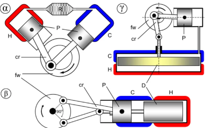
The Stirling engine has 3 base configurations α, β and γ (Fig. 1), [3]. Their layouts are different, but the working principle is the same. Each has a flywheel with two connecting rods. One of them moves with 90 degrees delay. The engines have a cold and a hot side. When they compress, the air is mostly in their colder side or colder part.
When the air expands, it is in the warmer part of the engine. The thermodynamic process can be considered quasi static, so the volume changing is isothermal. The huge advantage of this engine, that if it has regenerator, its effectiveness approaches the effectiveness of the Carnot cycle.
Fig. 1. The three base configurations of the Stirling engine.
H and C: hot and cold side, P: piston, R: regenerator, D: displacer, fw: flywheel, cr: connecting rod
The modern power engines use high compressed inert gas instead of simple air.
These engines usually run slow, in range of 100 - few 1000 rotation per minute, depending on the construction. See below their feature mentioned ‘traditional’ engine.
There are versions for high and low temperature difference as well. This is just a short review, see more at reference [2] or see more very expressive animations at reference [4].
2.1. α type engine
At this configuration (Fig. 1) [5], both rods end in a power piston. The cylinders usually are in 90o V shape arrangement. Some of α engines has parallel cylinders, their crankshaft is built with Ross-yoke together [6], [7]. In Fig. 1 the engine is in compression stroke. The air is mostly in the cold cylinder. When the common bearing of the connecting rods reaches the top, the engine starts the expansion stroke. The
H
H H
C
C C P
R
fw
fw
cr
cr
cr P D
P
90o
regenerator, which is heat storage with great surface, makes the engine more effective.
The regenerator was applied first time by Robert Stirling too [1].
2.2. β type engine
This configuration (Fig. 1) [8] has a common cylinder. On the left is the power piston. On the right site the so called displacer can be found. This is a piston like part, which makes no compression. This just drives the air to the proper side of the cylinder.
The engine in Fig. 1 is in compression phase. It is not seen, but the power piston has double connection rod, and the connection rod of the displacer is between them. The rod of the displacer slides in the center of the power piston. There is no regenerator in the figure, but it can be used.
2.3. γ type engine
This configuration can be built with high compression for high temperature difference [9], but this type can be a typical low temperature difference engine as well, [10]. Fig. 1 shows that type of engine. Some of them are able to work even with 20 Co difference. The displacer is much bigger than the power piston. They move like in the β type engine, but not in each other center, and they must not alternate with same amplitude.
2.3. Other types of hot air engines
The Ringbom engine [11] is very similar to the γ configuration. That is built for low temperature difference, but the big displacer is not moved by the crankshaft. The displacer is connected to a very sensitive air spring. If the power piston compresses the air, the air spring gets compressed too. That makes the displacer change its position.
The so called rotary engine [12] works as follow: its flywheel is the displacer, which works in a closed chamber. So, the power piston gets the pressure from underneath.
Remark: The Ericcson and the Manson engine are also hot air engines but not Stirling engines [13], [14]
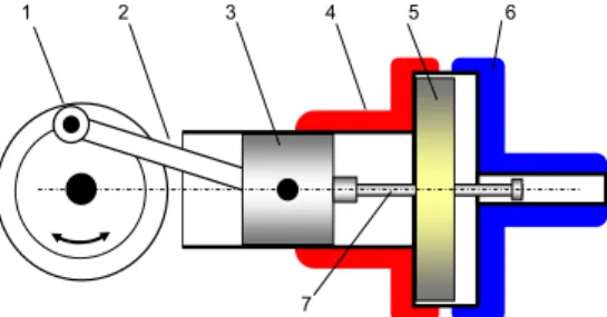
3. A novel hot air engine
This engine is much simpler than the previous ones (see Fig. 2). The huge difference is that here the piston moves the displacer directly not the crankshaft. There is only one connecting rod on the flywheel, which ends in the working piston.
The cylinder directly leads to the heat exchanger chamber, at its hot side. The cold side is at the front of it. The heat exchanger chamber is a cylinder, with bigger diameter, concentric with the working cylinder, just like the displacer, which fills the chamber with a gap. On the top of the piston, in the center, there is the so called cam rod, so the piston, itself, moves the displacer ahead and back. The displacer covers and isolates either the cold side or the hot side of heat exchanger. In ideally case, the displacer disc is a regenerator as well, so the air can pass through when it moves. The experimental engine has no regenerator, so there is a duct for the arising air stream.
Fig. 2. Novel hot air engine, 1: flywheel, 2: connecting rod, 3: power piston, 4: cylinder and the hot side of heat exchanger chamber, 5: displacer,
6: cold side of heat exchanger chamber, 7: cam rod 3.1. Detailed working cycle
This novel type is a two-stroke engine too. The first stroke is the compression phase (Fig. 3). The piston starts from the Bottom Dead Center (BDC), compresses the air and drives it though the displacer. The displacer does not move until the knob of the cam rod at the piston does not reach it. This happens when the piston is before the Top Dead Center (TDC) at a given distance. After that, the piston and the displacer move together until reaching the TDC. With this motion, all the air gets into the hot side of the heat exchanger. The air gets hot its pressure gets higher, so it gets ready to give mechanical work.
Fig. 3. Phases of work:
1. Compression phase, 2. End of the compression phase, 3. Expansion phase, 4. End of the expansion phase
The second stroke is the expansion (Fig. 3). The piston turns back, to the BDC driven by the expanding hot air. But the displacer still stays motionless insulating the cold side of the exchanger. In a given distance before the BDC the top knob of the cam rod reaches the displacer. After that it moves with the piston together until they reach the BDC. So the displacer drives the air to the cold side of exchanger, which gets cold, and insulates the hot side. The new cycle can start.
Remark: The engine is not self-starter, so to the start, it needs help to make the first stroke. The piston of a well-insulated engine in stationary state will be at the BDC.
1 2 3 4 5 6
7
T.D.C.
1. 2.
B.D.C.
3. 4.
The rotational direction of the traditional Stirling engines (α, β, γ) is given, but at this novel machine, the flywheel can run to both directions. That does not affect the working cycle.
4. Mathematical model
At first the motions of the piston and the displacer must be described. From that, the volume changes can be calculated. After that the stationary indicator diagram will be created for the novel engine, for a traditional engine and for the ideal Stirling engine, with the same parameters to compare them to each other. Finally, a calculation of the behavior of a running engine will be introduced, so the motor indicator diagram can be estimated by given speed. The calculation is carried out for different speeds, the power and torque diagram can be plotted.
4.1. Motions and volume changing
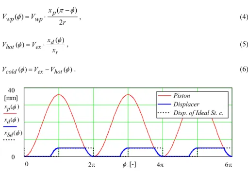
The crankshaft radius is r, the piston moves 2r distance in the cylinder. The displacer moves xr distance in the gap, between the two heat exchanger plates. It is motionless in the main part of the rotation, but after a certain point before the end of each stroke, they move together. This point is expressed by the pilot angle (α):
= −
r x
α arccos r r . (1)
The motion of piston is sinusoidal (at endless or very long connection rod), so a cosine function is used, to adjust the start position to the BDC, but the function of displacer is not so simple, because its motion is interrupted (3), (see Fig. 4).
)) cos(
1 ( )
(φ =r − φ
xp , (2)
( )
≤
∩
−
≤
− +
≤
∩
−
≥
−
≥
∩
−
≤
−
−
=
otherwise.
if ,
0
, 0 ) sin(
) 2 cos(
) cos(
if )),
cos(
1 (
, 0 ) sin(
) 2 cos(
) cos(
if )),
cos(
1 (
, 0 ) sin(
) cos(
) cos(
if )), cos(
) (cos(
φ α
π φ
α π
φ α
π φ
φ
φ α
π φ
φ α
π φ
r r r
xd (3)
The real motions are presented in Fig. 4, according to the above equations.
The following functions, where the Vwp entire volume of the cylinder and the Vex are the entire volume of the heat exchanger room, give the volumes of the working piston Vwp, the hot Vhot and the cold Vcold part of heat exchanger, according to the angle of rotation (φ),
r x V
Vwp wp p
2 ) ( )
( π φ
φ = ⋅ − , (4)
r ex d
hot x
V x
V ( )
)
( φ
φ = ⋅ , (5)
) ( )
(φ ex hot φ
cold V V
V = − . (6)
Fig. 4. Motions of piston (xp) and displacer (xd)
and the displacer of the ideal Stirling cycle (xSd), its motion is just a square signal At a traditional Stirling engine (α, β, γ), the functions of the hot Vctr and cold Vhtr
volume look this way: (function of the working piston is the same, as above)
r x V V
p s
ctr 2
) 2 (
−
⋅
=
φ π
φ , (7)
r x V V
p s
htr 2
) 2 (
+
⋅
=
φ π
φ . (8)
4.2. Quasi-stationery indicator diagram
When the engine runs extremely slow, there is time for heat exchange. The air has time to warm up and to cool down, so the air in the heat exchanger parts can be considered to reach the temperature of the given hot source (Th) and the cold sink (Tc).
The function of pressure comes from the Avogadro’s gas law, for the novel machine (p) and for the traditional one (ptr), with the same sizes and same temperatures are:
(
p wp)
mc cold h
hot T V T V V T
V m R
p( ) ( ) ( ) ( )
φ φ
φ φ
+ +
⋅ +
= , (9)
Piston Displacer
Disp. of Ideal St. c.
xp( )φ xd( )φ xSd( )φ
φ
40 [mm]
φ
φ [-]
2π 4π 6π
0 0
φ φ
(
p wp)
m cctr h
tr Vhtr T V T V V T
m R
p ( ) ( ) ( ) ( )
φ φ
φ φ
+ +
⋅ +
= . (10)
Remark: The Vp is the passive volume of the engine, the Tm is the medium temperature.
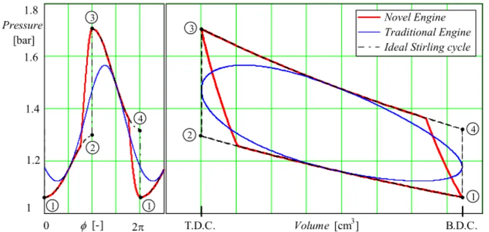
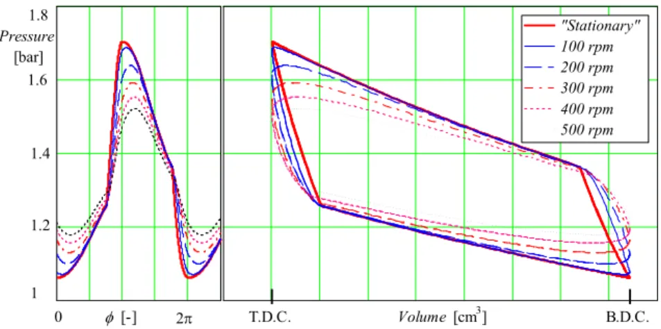
The pressures and the indicator diagram are presented in Fig. 5, according to the above equations.
Fig. 5. Pressures, as a function of angle of rotation (left) and the indicator diagram (right) of the novel and traditional engine and the ideal Stirling cycle,
Processes: between 1-2: isothermal compression; 2-3: isochoric heating; 3-4: isothermal expansion; 4-1: isochoric cooling, TDC is the top, BDC is the bottom dead center There is apparent difference between the novel and the traditional engines. The work of the working cycle is equal to the enclosed area at the indicator diagram. This work is given by the following equations for the novel W, and for the traditional engine Wtr as well:
φ φ φ
φ π
d d V
p d
W wp
⋅
= ∫ ( ) ( )
2 0
, and φ φ
φ φ π
d d V
p d
Wtr tr wp
⋅
= ∫ ( ) ( )
2 0
. (11)
In this configuration, the novel machine of same sizes, and with given pilot angle at same temperatures gives 86%, the traditional engine gives 77% work of the ideal Stirling cycle.
4.3. Analysis of the running engine
When the engine runs, there is no time to equalize the temperatures. The faster the engine runs, the less it completes the heat exchange. This is described by the differential equation of heat transfer,
0 φ [-] 2π
1.6 1.8
1 1.2 Pressure [bar]
B.D.C.
Volume [cm3]
Novel Engine Traditional Engine Ideal Stirling cycle
T.D.C.
4
1 2 3
4
1 1
2 3
1.4
T A dt k
mdT
c⋅ =− ⋅ ⋅∆ . (12)
Its two solutions give the warming and the cooling curves:
m t c
A k
h T e
T t T
⋅ ⋅
⋅
−
⋅
−
= ∆
)
( , and cm t
A k
c T e
T t T
⋅ ⋅
⋅
−
⋅ +
= ∆
)
( . (13)
The work of engine is not continuous, so these equations must be written-up section by section, for the hot and for the cool side of heat exchanger as well to cover an entire revolution (at least 3-3 pieces).
Remark: In the following equations, in the exponent, the C includes all the constants (k, A, c, m) as above and the time is expressed in brackets by the φ and n1 (given speed).
The equations of the first 3 hot sections are:
5 , 3 , 1 where , )
( )
( 2 1
) (
=
⋅
−
−
=
⋅
−
⋅ −
−
z e
T T T
T n
C z
c h h
hnlz π
α π φ
φ . (14)
The equations of the first 3 cold sections are:
4 , 2 , 0 where , )
( )
( 2 1
) (
=
⋅
− +
=
⋅
−
⋅ −
−
z e
T T T
T n
C z
c h c
cnlz π
α π φ
φ . (15)
These formulas are enough to describe the first 3 evolutions of the engine, enough to give a picture about the procedure. The results of the equations must be summarized by logical functions. In this article it is introduced just for one given speed (e.g. 100 rpm).
The logical summary of the hot Th100 and cold side Tc100 are:
( )
( ) ( ) ( )
−
<
≤
−
−
<
≤
−
−
<
≤
−
=
otherwise.
, 7 5
if ,
, 5 3
if ,
, 3 if
,
15 13 11
c hn hn hn
nl
T T T T
T φ π α φ π α
α π φ α π φ
α π φ α π φ
φ (16)
( )
( ) ( ) ( )
−
<
≤
−
−
<
≤
−
−
<
≤
=
otherwise.
,
, 6 4
if ,
, 4 2
if ,
, 2 0 if
,
14 12 10
c cn cn cn
cnl
T T T T
T φ π α φ π α
α π φ α π φ
α π φ φ
φ (17)
When the hot and the cold side are ready at given speed, the function of pressure - angle of rotation can be calculated. This is just an approach (because the temperature function contains the mass too), but it is not too far from the reality.
This equation gives the pressure according to the angle of rotation. It is similar to (9) and (10), but there the temperatures were constants. Here, the temperatures are functions of the angle of rotations:
(
p wp)
hcnl cold
hnl hot
nl V T V T V V T
m R
p ( ) ( ) ( ) ( ) ( ) ( )
φ φ
φ φ
φ φ
+ +
⋅ +
= . (18)
The speed of rotation (n1) in (14) and (15) is fixed for 100 rotations per minute. So, the quasi stationary and the 100 rpm pressure curves are ready, but to get an expressive picture about the behavior of the engine, all the procedure for 200, 300, 400, and 500 rpm could be made simultaneously.
As above, the pressure and the indicator diagram is drowned up (Fig. 6). At this engine, the 100 rpm curve encloses biggest area. After that, as is seen, by the rising of the speed, the enclosed area is smaller and smaller.
Fig. 6. Pressure versus angle of rotation diagram (left) and the Indicator diagram at different speeds (right) 4.4. Power and torque diagram
The given curves are closed, so it can be integrate, and the work of cycle can be calculated for a given speed:
φ φ φ
π φ π
d d V
p d
Wnl nl wp
⋅
= ∫ ( ) ( )
4 2
, (19)
therefore, the power Pnl and torque Mnl of a revolution at given speed will be known:
"Stationary"
100 rpm 200 rpm 300 rpm 400 rpm 500 rpm
0 φ [-] 2π
1.6 1.8
1 1.2 Pressure
[bar]
B.D.C.
Volume [cm3] T.D.C.
1.4
nl nl
nl W n
P = ⋅ , and
π 2 nl nl
M =W . (20)
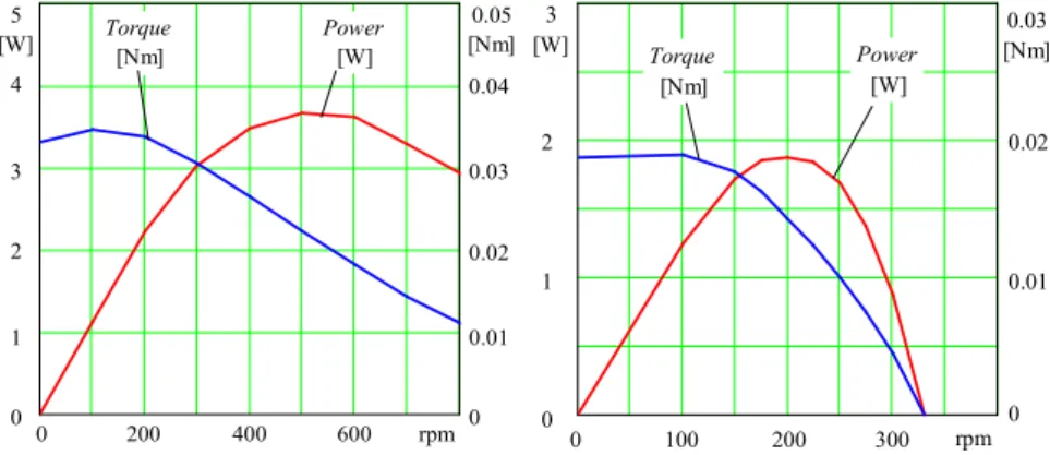
If those are calculated for certain speeds, these give the character of the engine. If those are calculated for the following few speeds (for 200, 300, etc. rpm, by a similar procedure), the inner power and torque diagram can be plotted, (see Fig. 7).
Fig. 7. The inner power and torque (left) and the shaft power and torque diagram (right)
The diagram below shows the inner power, so the power provided by the thermodynamic process. The highest speed of the engine, without load is about 330 rpm. At this speed, the inner power covers just the friction of the piston and the bearings and the loss of the inner steams. Considered, these losses the outer or the so-called shaft power, and the shaft toque diagram can be seen in the right side of Fig. 7.
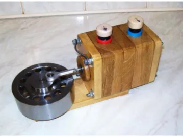
5. Experimental machine
Two experimental engines have been built. The first one was built in 2012 which had some teething problem but gave good ideas and led to the building of the other one.
The second engine was built in 2016 which can be seen in Fig. 8. This one was built in order to replace its electrical motor of the solution pump in a project which deals with the development of absorption refrigeration [15]. The inside of this small engine exactly looks like in the Fig. 2.
The description of this engine is the following: bore of working cylinder is ∅ 16 mm, stroke of piston 36 mm, so the swept volume is 7.24 cm3. Bore of displacer ∅ 75 mm, its stroke is 5 mm (variable), so the swept volume: 22.1 cm3. The heat exchangers [16] of the engine have 44.2 cm2 effective surfaces at both sides. In addition, at the hot side 7.2 cm2 surfaces are considered as heat exchanger, which is the swept surface of the working cylinder.
These inner parts are hidden, in the center of the wooden body. The engine is designed to use hot water as fuel, so it is surrounded with 2 tanks, as it can be seen in
0 0 0
200 400 600 rpm
0.01 5
[W]
1 2
0.05 [Nm]
0.02 0.04
0.03 4
3
Torque [Nm]
Power [W]
0 0
0
100 200 300 rpm
0.01 3
[W]
1 2
0.03 [Nm]
0.02 Torque
[Nm]
Power [W]
Fig. 8. One half of the body, closer to the flywheel, is for hot water as heat source.
Another half is for cold water as heat sink. Volume of each tank is 200 cm3, also the wooden body should be insulation against heat loss.
Fig. 8. Experimental engine
This engine is designed for low temperatures, and low temperature difference. It operates even at 30 ºC temperature difference. It could theoretically utilize any heat search, but the materials allow maximum 100 ºC.
6. Conclusion
In previous the novel model for a hot air engine was introduced. The novel engine has a lot of benefits comparing with the earlier types according to the theoretical mathematical models. This new model has designed for low temperature working media. A prototype was also developed and built which can be seen in figures.
Nomenclature
^ Logical function, ‘and’
A Area, [m2] k Heat transfer coeff.
[W·m-2·K-1] m Mass, [kg]
M Torque, [Nm]
n Speed of rotation, [rpm]
P Power, [W]
p Pressure, [bar]
Q Heat, [J]
r Crankshaft radius, [mm]
R Gas constant [J·kg-1·K-1] T Temperature, [K]
t Time, [s]
V Volume, [cm3] W Work, [J]
x Distance, [mm]
α Pilot angle, [-]
φ Angle of rotation, [-]
Open Access statement
This is an open-access article distributed under the terms of the Creative Commons Attribution 4.0 International License (https://creativecommons.org/licenses/by/4.0/), which permits unrestricted use, distribution, and reproduction in any medium, provided the original author and source are credited, a link to the CC License is provided, and changes - if any - are indicated. (SID_1)
References
[1] Biography of Robert Stirling, Encyclopædia Britannica, https://www.britannica.com/
biography/Robert-Stirling (last visited 10December 2017)
[2] Bachelier C. Stirling engines, a technology overview, Research Paper, Royal Istitute of Technology, Sweden, 2009.
[3] Gupta V., Sharma S., Narayan S. Review of Stirling engines, Acta Technica Corviniensis, Bulletin of Engineering, No. 1, 2016, pp.55–58.
[4] Keveney M. Animated engines, www.animatedengines.com, 2000, (last visited 10 December 2017).
[5] Karabulut H., Serdar H. S., Koca A. Manufacturing and testing of a V-type Stirling engine, Turkish Journal of Engineering and Environmental Sciences, Vol. 24, No. 2, 2000, pp. 71–80.
[6] Pieto J. I., Mendez A: Comparison between conventional and inverted Ross yoke drive mechanisms, 10th International Stirling Engine Conference, ISEC 2001, Verein Deutsher Ingenieure, Gesellschaft Energietechnik, Osnabrück, Sep 24-26, 2001, pp. 173–180.
[7] Tlili I., Musmar S. A. Thermodynamic evaluation of a second order simulation for yoke Ross Stirling engine, Energy Conversion and Management, Vol. 68, 2013, pp. 149–160.
[8] Maheswaran K. G., Ameer Ahamed M., Karthikeyan N. T., Balachander R. Design and manufacture of Betha Stiling engine, International Journal of Innovative Research in Science, Engineering and Technology, Vol. 6, Special No. 7, 2017, pp. 174‒182.
[9] Damirchi H., Najafi G., Alizadehnia S., B Ghobadian B., Yusaf T., Mamat R. Design, fabrication and evaluation of Gamma-Type Stirling engine to produce electricity from biomass for the micro-CHP system, Energy Procedia, Vol. 75, 2015, pp. 137–143.
[10] H. Arafat, K. Shubhra, H. Sazzad: Fabrication & performance test of a low temperature differential Stirling engine, International Journal of Scientific & Engineering Research, Vol. 5, No. 1, 2014 pp. 706-711.
[11] Senft R. J. Ringbom Stirling engines, Oxford University Press, 1993.
[12] Foster P. R. Innovative rotary displacer Stirling engine: Sustainable power generation for private and fleet vehicle applications, Journal of Technology Studies, Vol. 37, 2011, pp. 95–107.
[13] Ewing J. A. The steam-engine and other heat-engines, Cambridge University Press, 1910.
[14] Peabody C. H. Thermodynamics of the steam engine and other engines, In: Hot air engines, Handbook, Massachusets Institute of Technology, 1889.
[15] Fedorčák P., Košičanová D., Urka D. Comparison of energy consumption in compressor and absorption cooling Pollack Periodica, Vol. 7, No. 2, 2012, pp. 83‒90.
[16] Varga T., Szepesi G., Siménfalvi Z. Horizontal scraped surface heat exchanger - Experimental measurements and numerical analysis, Pollack Periodica, Vol. 12, No. 1, 2017, pp. 107‒122.