The „Phantom” Delta Robot
A New Device for Parallel Robot Investigations
János Somló, Gábor Dávid Varga, Márk Zenkl, Balázs Mikó
Bánki Donát Faculty of Mechanical and Safety Engineering, Óbuda University, Népszínház u. 8, H-1081 Budapest, Hungary
E-mail: somlo@uni-obuda.hu; miko.balazs@bgk.uni-obuda.hu
Abstract: A new device is proposed for parallel robot investigations. Basically, a robot with equilateral basic and working triangles, driving arm and parallelogram connection is considered, which is called Clavel’s Robot. This device is constructed in a way that the sizes of elements may be changed in certain regions. In doing so, different robots can be realized with the reconfiguration of the same device and different accuracy, stiffness, compliance, and force characteristics, etc. can be studied. For example: accuracy maps can be prepared. Through changing the constructional elements (principle, shape, strength, etc.) the effect of these changes may be estimated. We remark that the Phantom Robot may be used not only for the investigation of Clavel’s but also, proposed by us the General Triangle Parallel Robot.
The presented device is devoted to construction studies. Works can be extended further to the investigation of drives and controls. We considered it necessary to summarize, and give somewhat new directions, for the solutions of inverse and direct transformation problems.
The realized device proved very suitable. The rather simple and cheap measurements were realized at the usual university laboratory level. The first experiments proved a good performance.
1 Introduction
Parallel robots are more and more promising in the solution of recent application problems of robotics technology. Parallel robot applications own several outstanding features which make them more preferable than the use of serial robots:
They are cheap compared to serial robots of the same class.
The motors that move the parallel arms can be allocated together, on the same platforms, close to each other. Their relative positions have much less restrictions than the same for serial robots.
The constructional elements of parallel robots are simpler than those for serial robots.
The service is simpler, the replacements are cheaper.
The solution of inverse and direct kinematics problems are of the same difficulty class as those for serial robots. That is, these can effectively be solved without any difficulty.
Sometimes, parallel robots promise a better solution for special application tasks than the serial ones. Sometimes the solutions are, at least, equivalent.
Frequently, the application of a parallel robot is easier than serial one.
The force (moment) characteristics of the parallel robots are better than those for serial ones. This is due to the parallel actions of arms. For example, the static force acting on a serial arm can be distributed to three forces in parallel robot cases giving less deformation and providing more accuracy.
The present paper deals with the topic of the design of the parallel robots mechanical part. This part provides the basic task of manipulation of the objects by the machine elements and parts.
In this work the questions concerning the drives, the control systems, instrument units, etc., are not taken into consideration. Of course, the above aspects have significant effect on systems performances, but those are the topics of other investigations.
We proposed and built a so-called “PHANTOM” Delta Robot which makes it possible to investigate the practical performances of Delta robots in general, and which covers quite a wide class of possible robot constructions. We performed as much research and experimental investigations as possible with the help of the given device.
Concerning the history of parallel robots here we give only a short review. A rather detailed picture may be obtained from Bonev [3] and others. The intensive development of the Delta robots may be contacted with the works of R. Clavel [1, 2]. The Delta robot idea and the most popular constructions are those which are proposed in the above works.
Monograph of J.-P.Merlet [4] is a summary of most important results. A picture of how wide the choice of parallel robots is today can be obtained from the material provided by ParalleMIC (the Parallel Mechanism Information Center). Recently, more than 26 companies are producing parallel robots [3].
The constructions of the variants of the parallel robots are very wide. But the dominant variant is the Delta robot. This robot uses DC or AC servo driven motors rotating the thing-rods (motor arms) which move the (shin) parallelograms
Development of the Delta robots began at the end of the 80s, during the last century. Solutions for the inverse and direct kinematics problems were found which were necessary for them to work. A number of publications are available regarding this topic. New, rather sophisticated results were obtained by Murray [5, 6]. Based on his results software for direct and inverse problem’s solutions were developed which are widely available [7].
2 Constructionof the “Phantom” Robot
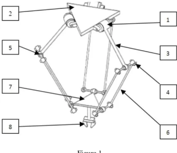
Figure 1 shows a Delta robot construction. This is very similar to the construction given in R. Clavel’s US Patent description [1].
Figure 1 The Delta robot construction Where:
1- the driving motor arm coupling joint 2- upper platform (basic triangle) 3- driving arm (thing-road) 4- Parallelogram joint
5- Driving arm, parallelogram joint 6- Parallelogram arm (shin)
7- Lower platform (working triangle) 8- Tool
In industrial Delta Robot constructions all the above elements have fixed quantities. In case of a presented device some of the mechanical elements may be easily changed. This device is named “Phantom Delta” robot. The device is designed by considering easy modification of shape and size. In the Phantom Robot many elements may have different and/or adjustable sizes. Figure 2 shows the adjustable elements of the investigated Phantom Delta robot. These elements are the distance of rotation point from the centre of basic triangle, the rotation arm lengths, and the distance of driven point on the working triangle from the centre of this triangle.
Figure 2
The adjustable elements of the „Phantom” Delta robot
In the present work the size of the parallelogram is kept constant. It has practical reasons (availability): in the future we plane to change the size of parallelogram, too.
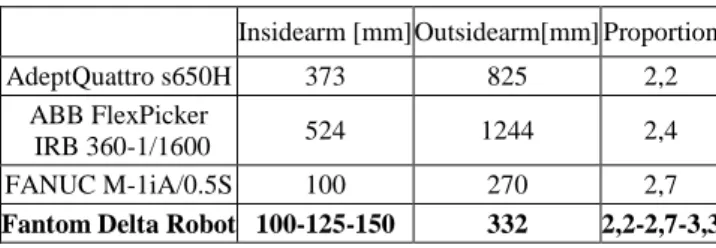
The parameters of the Phantom Delta robot should be close to the same as of the robots intensively used in industry. For this goal the Table 1 was created to helpmake a proper choice.
Table 1 Robot arms sizes
Insidearm [mm] Outsidearm[mm] Proportion
AdeptQuattro s650H 373 825 2,2
ABB FlexPicker
IRB 360-1/1600 524 1244 2,4
FANUC M-1iA/0.5S 100 270 2,7
Fantom Delta Robot 100-125-150 332 2,2-2,7-3,3
The intensive research, development and design work in the field of parallel robots was reviewed in diploma work of M. Zenkl [8]. The Phantom Robot has been built according to the constructional schema shown in Figure 3.
Figure 3
Constructional schema of the Phantom Robot Where:
K1, K2, K3 are the basic triangle driving arm rotation centres
P1, P2, P3 are the working triangle joints rotation centres
R1 is the driving arm rotation centres allocation radius
R2 is the working joints centres allocation radius
In Zenkl’s work [8], among others, the following problems were solved.
The basic triangle construction
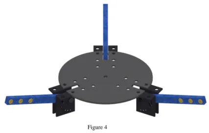
After analysing a number of variants, a final version of basic triangle was developed. This is shown in Figure 4.
Figure 4 Basic triangle Robot arm, parallelogram joints construction
Analysing a number of variants, the one on Figure 5 was accepted. A simple sliding bearing is applied made from bronze. Ball bearings and spherical joints were rejected. The given construction is very easy to implement. Nevertheless, it could be applied very effectively.
Figure 5
Driving arm, parallelogram joints The working triangle joints construction
The working triangle joints were designed as shown in Figure 6. The parallelogram connections were produced as shown in Figure 5.
Figure 6
The working triangle joints construction Elements fixing the driving arms in fixed position
The Phantom Delta Robot has no electrical drives. The arms are taken to some given position by hand and are fixed with bolts. With the given construction a discrete points realisation was chosen. As it is demonstrated in Figure 7, an element is introduced for each arm which has 7 holes located to realize a 15 degrees angle change. So, 7*7*7=343 position can be investigated.
Figure 7
Elements fixing the driving arms in fixed position
The presented mechanism was developed for estimating the opportunity of simple and effective build of Delta Type Parallel Robots. Namely, to analyse how the accuracy changes, force characteristics, etc. in function of geometric size.
(Without developing a new robot) The way of realizing the above may be: accept robot parameter values which are the closest to the realized version of the Phantom Robot; solve the direct and inverse transformation problems. Then, compare the measurement results with the theoretical ones to get characteristics.
Below, a treatment of the direct and inverse transformation problems for Delta Robots will be given, slightly different in interpretation of the results from the published ones.
3 Inverse and Direct Transformation of Delta Robots
As it has been outlined in the Introduction the inverse and direct transformation problems for Delta robots are solved. Several variants of the solutions are available. Here, for the sake of completeness, we give some details of the approaches used in the present work.
3.1 Inverse Transformation
The task formulated for robot working process is usually formulated in the world coordinate systems. In the case analysed in the present work translation motions are considered. Three degree of freedom Delta robots are used.
The inverse transformation task is formulated in the way that three world coordinates values x0, y0, z0, are given and the robot’s joint coordinates values q1, q2, q3 realizing those are to be determined.
Let us allocate one of the parallel robot legs driving arm (central line) as is shown in Figure 8. That is, this central line coincides with axis y when the joint coordinate value q1 is zero. The axis z is allocated in point x=y=0. The positive direction of z is downward.
For more details we refer to Figures 2 and 3.
We use q1, q2 and q3 for the joint coordinates of the robots. These, are the motor driven arm’s angular positions. The q1, q2 and q3 have zero values at the horizontal positions of the driving arms.
The Delta robot quantities necessary for inverse transformation are shown in Fig.
8.
Figure 8
Robot arm quantities necessary for inverse transformation
Let us deal with the first arm. (Later the results will be extended to the second and third arms, too) This arm is allocated in the coordinates system as shown in Figure 8. The driving arm (central line) is in axis y. The axis of rotation of the driving arm there is in the point A1. This point’s distance from the origin is “a”. The arm rotation radius is “r”. Point B1 is the arm-parallelogram rotation reference point.
E1 is the parallelogram-working triangle rotation reference point. The length of the central line of the parallelogram is “d”. The central point of the work triangle is D1. The distance D1E1=e.
The basic triangle size is ”H”, a=√3
6 H.The working triangle size is “h”, e=√33h.
According to Figure 8:
E1=(x0; y0 –e; z0).
The goal is to determine the B1 point coordinate values. Then, the solution of the inverse problem is:
q1 = arctangy zB1
B1−yA1 (1)
The point B1 is the intersection of a circle in plane yz with centreA1 and with radius “r” and a sphere with centre E1 and radius “d”.
That is:
(𝑦𝐵1-𝑦𝐴1)2+ (zB1–zA1)2= 𝑟2 (2)
and
(𝑥B1–𝑥E1)2 + (𝑦B1–𝑦E1)2 + (𝑧B1–𝑧E1)2 = 𝑑2 (3) Because
xB1 =0 and xE1=x0 (yE1=y0 –e; zE1=z0)
(𝑦B1 – 𝑦E1 )2 + (𝑧B1 – 𝑧E1)2 = d2 +𝑥02 (4) Equation (4) is the equation of the circle in which the sphere crosses the yz plane.
Solving equations (2) and (4) (the solutions are the intersection points of the two circles) we obtain the solution of the inverse kinematics problem for the first arm.
(The determination of the crossing points of two circles is a simple task of elementary mathematics.)
This way of the solution of the inverse transformation problem is called the Two Circle Algorithm (TCA).
Concerning the other two arms, we call attention to the following. If we rotate the xy axes by angle α1, we reach a situation similar to the original, with the only difference that the allocation of the working point is related to the new axes change.
That is, the computations for the other two arms are exactly the same as for the first arm with the difference that instead of x0, and y0 new values x1 and y1 should be substituted (z1=z0).
Let us consider as second arm the one rotated by α1= - 120o in negative direction.
The new x,y axes are indicated in Figure 7 as x1 and y1.
The x1 and y1 values may be obtained by homogeneous transformation as
( 𝑥1
𝑦1
𝑧1 1
) = 𝐻̿−𝛼1( 𝑥0
𝑦0
𝑧0 1
) (5)
𝐻̿−𝛼1= (
cos(−120°) sin(−120°)
00
− sin(−120°) cos(−120°)
10 00 10 00 01
) (6)
x1= x0cos(−120°) - y0sin(−120°)
y1 =x0sin(−120°) + y0cos(−120°) (7)
In similar manner
x2= x0cos(−240°) - y0sin(−240°)
y2=x0sin(−240°) + y0cos(−240°) (8)
The Two Circles Algorithm (TCA) is demonstrated in Figure 9.
Figure 9
Demonstration of the Two Circle Algorithm
3.2 Direct Transformation
The solution of inverse problem makes it possible to solve motion planning problems and it has the most important role in application planning. The solution of direct kinematics problems may have importance in accuracy, force (moment) management, etc. problems.
As it was outlined in the above section the individual arms may be treated separately at the solution of inverse problem. The situation is different at the solution of the direct problem.
The direct transformation problem may be solved using the following idea.
Figure 10 (similar to those proposed by Williams [9]) shows that a virtual parallelogram may be introduced to each of the driving arms which allows to reduce the motions of the parallelograms working point straight to the working point of the robot. Point P may move only along a sphere with radius “d” around point “B” at any motion. Virtual points B1v, B2v, B3v are introduced in such a way that virtual parallelograms BiPiBivD(i=1,2,3) are constructed. The BiBiv vectors are parallel with the PiD vectors (i=1, 2, 3). When looking for the solution of the direct kinematics problems we should consider points obtained by the motions of parallelograms central line end points (Pi) on a sphere with radius “d”
which has the central point in Bi (i=1, 2, 3). At the same time points Di also move along a sphere with radius “d” and centre Biv. The solution of the direct kinematics problem is when the three arms have one common D1=D2=D3=D point. That is the solution is the common (intersection) point of the three spheres.
Figure 10 Direct transformation
Now, let us determine the coordinates of the virtual points B1v, B2v and B3v.
Figure11
Determination of virtual points According to Figure 11:
𝐵1̅̅̅̅𝑣= (− 0
𝑓 − 𝑟 ∗ cos 𝑞1+ 𝑒 𝑟 ∗ sin 𝑞1
) = ( 𝑥𝐵1𝑣 𝑦𝐵1𝑣
𝑧𝐵1𝑣) 𝐵2̅̅̅̅𝑣= (
(𝑓 + 𝑟 ∗ cos 𝑞2− 𝑒) ∗ cos 30°
(𝑓 + 𝑟 ∗ cos 𝑞2− 𝑒) ∗ sin 30°
𝑟 ∗ sin 𝑞2
) = ( 𝑥𝐵2𝑣 𝑦𝐵2𝑣
𝑧𝐵2𝑣) 𝐵3̅̅̅̅𝑣= (
−(𝑓 + 𝑟 ∗ cos 𝑞2− 𝑒) ∗ cos 30°
(𝑓 + 𝑟 ∗ cos 𝑞2− 𝑒) ∗ sin 30°
𝑟 ∗ sin 𝑞3
) = ( 𝑥𝐵3𝑣 𝑦𝐵3𝑣
𝑧𝐵3𝑣) (9) The three spheres equations are:
(𝑥0 – 𝑥B1v)2 + (𝑦0 – 𝑦B1v )2 + (z0 – 𝑧B1v)2 = 𝑑2 (𝑥0 – 𝑥B2v)2 + (𝑦0 – 𝑦B2v)2
+ (z0 – 𝑧BvV)2 = 𝑑2
(𝑥0 – 𝑥B3v)2 + (𝑦0 – 𝑦B3v )2 + (z0 – 𝑧B3v)2 = 𝑑2 (10) The Equations should be solved for x0, y0, z0.
The direct transformation problem may be solved by determining the intersection point of the three spheres x0, y0, z0.. An algorithm for the solution is given in Williams [9].
The algorithm is named Three Sphere Intersection Algorithm (TSIA). This gives x0 , y0 , z0 : having the data: xBiv.yBiv, zBiv (i=1, 2, 3) and “d”.
The solution of direct transformation task is:
The robot hardware data are introduced (a, e, r, d; (a is the basic triangle side; f=√3
6a
e=𝑏 ∗ √3; b is the working triangle side).
Having q1, q2, q3
xBiv.yBiv, zBiv (i=1, 2, 3) are determined according to Eq. (9)
TSIA is applied
x0 , y0 , z0 is obtained
4 Investigations Using the Phantom Robot
A draw of the final version of the Phantom robot is given in Figure12. In the thesis work of Varga [10] a number of investigation studies are described, and some of the results are reviewed below
.
4.1 Accuracy Studies
The studies were directed to the investigation of accuracy and repetition. A construction variant was chosen characterized by data of Table 2.
Table 2
Sizes and accepted values for the computations
a[mm] b[mm] c[mm] d[mm]
1 39,98 332,32 209,74 149,62 2 39,05 332,55 213,54 149,14 3 39,51 331,9 215,122 149,16
Accepted values 39 332 205 149
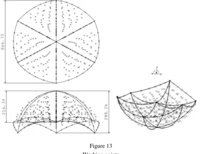
Computation of the theoretical values of the working points was performed using the equations of the direct kinematics. The graphics of the working points are given in Figure 13.
Figure 13 Working points
Besides the working points the work space is given on Figure 13, too.
We performed the measurement of all experimental points. We got pictures that were much similar to Figure 13 in shape. But for example the size 566,72 mm on computed picture was 530,12 mm. The same in measurement was 288,26 mm the
“high’s” of the computed was 273,72 mm.
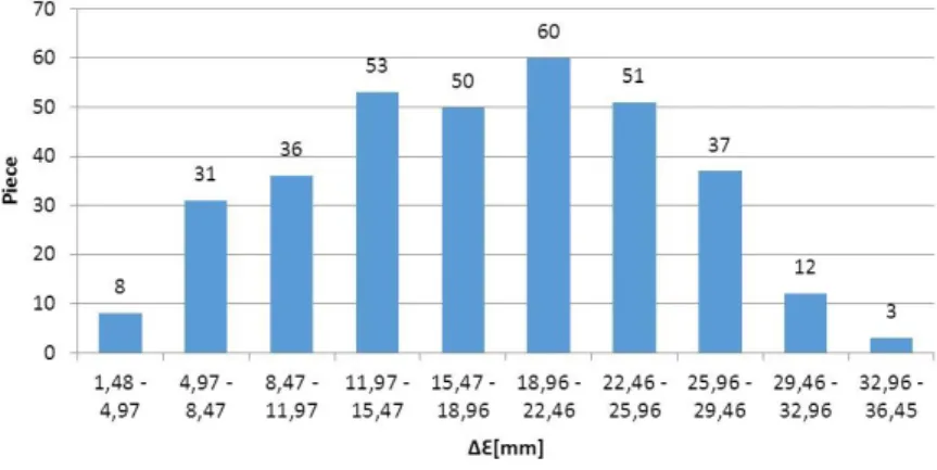
The results are summarized in Figure 14, where on the horizontal axes the absolute value of accuracy is shown.
∆∈= √(∆𝑥∈)2+ (∆𝑦∈)2+ (∆𝑧∈)2
The difference of the computed and measured values where:∆𝑥∈; ∆𝑦∈; ∆𝑧∈
This diagram very well characterizes the accuracy of the device.
But these results are given only for the demonstration of investigation opportunities. This is only an example of showing that a certain robot configuration may result in inappropriate characteristics.
Changing the shapes the sizes, etc. similar measurements can be performed for better and better understanding of the parallel robot features.
Figure 14 Dispersion of Difference
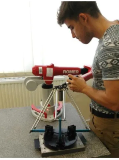
The investigations were performed using the coordinate’s measurement machine of the measuring technology lab of Óbuda University. Photography of the phantom robot is shown in Figure 15.
4.2 The Use of Parallel Robot as Leg of Exoskeletons
In the above the accuracy of Phantom robot was analysed. It should be emphasized that the accuracy may be increased using very simple means.
Nevertheless, there are applications where the provided accuracies are enough for satisfying the requirements. For example: the parallel robot can be used as one of the leg of exoskeletons. Such research is on at Óbuda University [11].
Figure 15 Measurement
5 Summary
The developed delta robot has variable size and no drive in order to investigate the geometric properties of different constructions. It was named Phantom Delta Robot. This made possible to investigate features not available for existing (in given construction) robots. This opens new ways to develop robots which are reconfigurable, accurate, stiff and compliant.
References
[1] Clavel, R. (1990) U.S. Patent No. 4,976,582. Washington, DC: U.S. Patent and Trademark Office
[2] Clavel, R. (1991) Conceptiond’un robot Parallelerapide 4degre’s de Liberte. Ph.D. thesis EPFL Laussane, Switzerland
[3] Bonev, I. (2014) Delta Parallel Robot, The Story of Success, The Parallel Mechanisms Information Center, (http://www.parallemic.org)
[4] Merlet, J. P. (2012) Parallel robots (Vol. 74) Springer Science & Business Media
[5] Zsombor-Murray, P. J. (2004) Descriptive geometric, kinematic analysis of Clavel’s “Delta” Robot; Centre of Intelligent Machines, McGill University [6] Zsombor-Murray, P. J. (2009) An improved approach to the kinematics of
Clavel’s DELTA robot. Intelligent Machines, McGill University
[7] Marginally Clever Software (2012) Delta robot, Forward/InverseKinematics,www.marginallyclever.com/other/samples/fkik -test.html
[8] M. Zenkl, Design of Phantom Delta Robot Construction 2017, Budapest, BSc Thesis Work, Óbuda University
[9] Robert L. Williams II, Ph.D., The Delta Parallel Robot: Kinematics Solutions Mechanical Engineering, Ohio University, October 2016
[10] D. Varga, Fantom Delta Robot Precision Measurement 2017, Budapest, BSc Thesis Work, Óbuda University
[11] Somló J., Paniti I., Rudas I. (2016) Léptetőszerkezet humanoid robothoz (Stepping device for humanoid robots), Presented for Hungarian Intellectual Property Office, P1600241, unpublished
![Figure 10 (similar to those proposed by Williams [9]) shows that a virtual parallelogram may be introduced to each of the driving arms which allows to reduce the motions of the parallelograms working point straight to th](https://thumb-eu.123doks.com/thumbv2/9dokorg/1237732.95485/12.748.251.506.368.678/figure-similar-proposed-williams-parallelogram-introduced-parallelograms-straight.webp)