General Triangle Parallel Robot (GTPR) Basic Features of a New Robot Type - Kinematics and related Application Issues
János Somló
Óbuda University, Budapest, Hungary somlo@uni-obuda.hu
Abstract: A new robot type is proposed herein, which is named, General Triangle Parallel Robot (GTPR). This robot differs from the widely used Delta robots (Clavel Delta robot) in the respect that it’s basic triangle (and the similar working triangle) may be any general triangle. The method of generation of GTPR is given in the present paper. The general method of determination of inverse transformation problem for GTPR is outlined. So, any working process may easily be realized, by any GTPR. Because GTPR covers a much wider class of devices, as the special case the Delta robot, GTPR may yield a number of advantages. This robot type may be advantageous from the point of view of simplicity and effectiveness of constructions realizing different applications (for example stepping). It is a nice feature that the solution of kinematics problems is extremely simple. For these robots, the drive allocations may be solved very effectively. It is possible to construct such triangles, which are advantageous, from the point of view of static forces, Etc. Sometimes these robots are referred as GTP(S)R, where (S) indicates the author (Somlo).
Keywords: Parallel robots; Delta robots; Clavel; General triangle parallel (Somlo) robot;
Inverse transformation; Direct transformation; Stepping robots
1 Introduction
Parallel robots are more and more promising, in the solution of recent application problems of robotics technology. One of the fields, where these robot types may promise a breakthrough, are the stepping robots.
In the present paper, we propose a new type of parallel robots which is, in fact, the generalization of the well-known Clavel robot (see later).
We name the new robot type, General Triangle Parallel (Somlo) Robot.
Parallel robots own several outstanding features which make them suitable for the solution of a number of applications, over the use of serial robots. These features are:
J. Somló General Triangle Parallel Robot (GTPR) Basic Features of a New Robot Type - Kinematics and related Application Issues
They are cheap compared with serial robots of the same class
The motors moving the parallel arms can be allocated together, on the same platforms, close to each other in preferable places, leaving space for gear trains, etc.
The kinematics problems may easily be solved and applied to the solution of motion planning problems
The forces on the arms are distributed. That is three components are present instead of one in the case of serial robots. Accordingly, rather favourable proportions of arm masses to other masses may be realized.
Sometimes, parallel robots promise better solution for special tasks than the serial ones. These kind of tasks are for example, the solution of stepping motions.
1.1 History Basics
The history of parallel robots was considered including several authors, Bonev [3]
is one of the most spanning. The recent development of the parallel robots (Delta robots) is based on the pioneering work of professor R. Clavel [1, 2]. The Delta robot idea and construction, belonging to him, is the most popular direction.
Monography of J.-P. Merlet [4] is a summary of most important results.
A picture of the wide choice of parallel robots can be obtained from the material provided by ParalleMIC (the Parallel Mechanism Information Center). Recently, more than 26 companies are producing parallel robots (source:
www.parallemic.org / WhosWho/ Comp Robo.html).
The construction variants of parallel robots are very wide. But the dominant variant is the Delta robot of the Clavel-type. This robot uses DC or AC servos rotating the thing-rods and shin parallelograms (or Kardan mechanisms) moving a point of the work triangles (see below).
The development of Delta robots began its story at the end of 80s. The solution of the inverse and direct kinematics problems was necessary for the work and was solved. A number of publications are available on this topic. New, rather sophisticated results were obtained by Zsombor Murray [5, 6]. Based on these results, software for direct and inverse problem solutions were developed which are widely available [7].
Parallel robots are more and more promising in the solution of recent application problems of robotics technology.
A huge number of homemade devices have been developed. LEGO parallel robots can be made, too. At the cheapest end, there is the Novint Falcon which is a 3D joystick. But, in fact, this is a perfect Delta robot for as little as, 250 Euros.
The construction variants of parallel robots are diverse. But the dominant variant is the Delta robot. This robot uses DC or AC servos driven motors rotating the thing-rods and shin parallelograms (or Kardan mechanisms) moving a point of the work triangles.
The software developments were restricted to Delta type robots. Delta type robots have equilateral triangles as basis and work triangles. These are special cases of general triangles parallel robots discussed in the recent article. The software developments, until now, where developed for equilateral cases because of no need for other cases.
The practical applications, until now, are mostly solved by Delta type robots. The research work dealing with other types are sparse. The robots Tripteron and Quadrupteron were proposed by the Laboratoire de robotique Laval (Quebec, Canada). These are different than the general triangle parallel robots discussed below.
GTPR promises great advantages, in many fields of robot applications. It is especially true, for example, for stepping devices, based on parallel robots. The advantages are from better opportunities of manipulation of work spaces.
Zsombor Murrey in works [5, 6] solved the inverse and direct kinematics problem of Delta robots. These results are not restricted to Delta robots. The authors of the above papers emphasized that his results are rather general, but did not indicate the way of extended use. The present paper solves this task and propose and some practical methodologies for the inverse and direct kinematics determination, for general triangle parallel robots.
2 Delta Robot (Clavel-Type)
On Figure 1 a Delta robot construction is given. This is very similar to the construction given in R. Clavel’s US Patent description [1]
J. Somló General Triangle Parallel Robot (GTPR) Basic Features of a New Robot Type - Kinematics and related Application Issues
Figure 1 A Delta robot structure Here:
1- upper platform (basic triangle) 2- driving arm axis
3- driving arm 4- parallelogram
5- driving arm, parallelogram joint
6- parallelogram, lower platform (working triangle) connecting joint 7- lower (working) platform
The simplest imagination of the working of these devices is:
There are 3 arms rotating in vertical plane. The centre points of their rotation are in the edges of an equilateral triangle in x, y plane.
The end points of the arms are coupled with the coupling elements of the parallelogram mechanism. The construction provides that the working point (for example, the centre of the working triangle) moves in a plane parallel with the basic triangle. The motion is activated by the rotation of the arms. Because the arms are coupled with working parallelogram units which are coupled with the working triangle in a special way at the motion of the arms the lower end of the parallelograms may only move in a parallel with the basic triangle plane.
When the arms are moving the working triangle edges move but the working triangle stay similar (and the sides parallel) with the basic triangle (see: Figure 2).
2.1 Inverse Transformation
Let us consider a Delta robot. In Figure 2 the upper view is given, as it can be seen, from the direction of z axis.
Figure 2
The basic and working triangles The parameter values are as indicated in Figure 2.
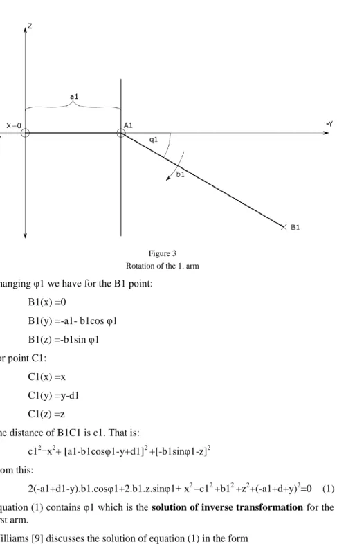
The driving arms move the working point through the motions of points B1, B2, B3, which are the results of rotation in vertical plane as it is demonstrated in Fig.
3. On this figure the motion of the 1st arm is shown.
Let first consider a point when the first driving arm is in horizontal position. Let at this point q1= φ1=0
J. Somló General Triangle Parallel Robot (GTPR) Basic Features of a New Robot Type - Kinematics and related Application Issues
Figure 3 Rotation of the 1. arm Changing φ1 we have for the B1 point:
B1(x) =0
B1(y) =-a1- b1cos φ1 B1(z) =-b1sin φ1 For point C1:
C1(x) =x C1(y) =y-d1 C1(z) =z
The distance of B1C1 is c1. That is:
c12=x2+ [a1-b1cosφ1-y+d1]2 +[-b1sinφ1-z]2 From this:
2(-a1+d1-y).b1.cosφ1+2.b1.z.sinφ1+ x2 –c12 +b12 +z2+(-a1+d+y)2=0 (1) Equation (1) contains φ1 which is the solution of inverse transformation for the first arm.
Williams [9] discusses the solution of equation (1) in the form
Eicosφi+Fisinφi+Gi=0 (2)
In this case:
Ei =2(-a1+d1-y).b1 Fi =2.b1.z
Gi =x2 –c12 +b12 +z2+(a1+d-y)2
In [9] the tangent half-angle substitution is used and closed formulas are obtained for determination of the φ1 value. For the determination of φ2, φ3 values transformation of the x, y, z quantities are necessary.
Solving the equations for any x, y, z value we get the proper φ1, φ2, φ3 values, that is the results of the inverse transformations.
The proper motion of the parallel robot may be realized if for given x, y, z values the φ1, then similarly the φ2, φ3 values are determined and input as the proper command for the driving motors.
For the inverse transformation, in the literature, together with the above, a number of other methods is also outlined. Computer programs for the solution are available, too [7].
One of the possible solutions is based on the following fact.
Point B1 moves on a circle in the yz plane. A sphere with radius “c1” and with centre in point x, y-d1 and z intersects the yz plane in a circle with radius
√𝑐12−𝑥2. The common point (points) of the two circles give the solution of the inverse problem.
This solution may be named the “Two Circle Intersection” method [12].
3 General Triangle Parallel Robot (GTPR)
In the present paper we propose a new type of parallel robots.
The difference of this from Delta robot (Clavel type) is that the basic triangle and accordingly the similar working triangle is any general triangle.
So, the Delta robot is only a special case of the GTPR when the triangle is an equilateral one.
At the general triangle parallel robots, we restrict our attention to a construction variant of parallel robots where (as in most of the applied in practice robots) rotating driving arms and special parallelogram mechanism moved by them are applied and the rotation of the arms result the working triangle motion in parallel with the basic triangle plane. The working triangles are similar to the basic triangles. The working points may be the centre of the working triangle or any other point of the working triangle.
J. Somló General Triangle Parallel Robot (GTPR) Basic Features of a New Robot Type - Kinematics and related Application Issues
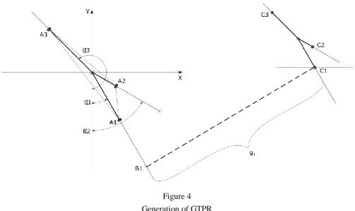
Figure 4 Generation of GTPR On Figure 4 we show how a GTPR is generated.
Point “O” is the centre of the coordinates system x, y, z.
The 1st arm of the robot is rotating in a vertical plane. (Vertical plane is perpendicular to x, y plane.) The plane of rotation goes through “O”. The angle of the rotation plane is α1. The arm rotation centre distance from “O” is s1. The rotation arm length is r1.
The 2nd and 3rd arms have similar structure as it is shown in Figure 4. The corresponding angles are α2 and α3.
The triangles A1A2A3 and C1C2C3 are similar. Any corresponding geometrical elements of these has proportional length.
We use the D(N,M) operator to indicate lengths. For example:
D(O,A1)= s1 the distance to the first rotation axis from the centre point O.
Other examples are:
D(W,C1)= p.D(O,A1); D(C1,C2)=p.D(A1,A2); etc.
As it was mentioned, the basic and working triangles are similar.
The value “p” is the coefficient of proportion.
Any GTPR may be determined by giving the following data:
α , α2, α3, s1, s2, s3, r1, r2, r3, g1, g2, g3, p
Where g1, g2, g3 are the lengths of the parallelograms. (lengths of the central rods).
For example, for the Delta robot analysed above:
α1=0, α2=120𝑜 , α3=240𝑜
s1=s2=s3=(√3/3).H (H is the side of the equilateral triangle) r1=r2=r3=r
c1=g1=g2=g3=g h=p.H
d1=p.a1
p is the given value of proportion coefficient.
3.1 Determination and Symbol of the GTPR
According to the above, a GTPR may be determined as follow:
Let us allocate in xy plane a general (basic) triangle with edges in points A1, A2, A3. Let in the vertical plane including the O,A1; O,A2; O,A3 sections, around points A1, A2, A3 arms with the proper lengths rotate.
The arm is joined with parallelogram mechanism in proper way. The other
“end” of the parallelogram has it joint axis on the working triangle. The working triangle is similar to the basic triangle. The parallelogram mechanism provides that the corresponding sides of basic and working triangles stay parallel during the motion of the working point.
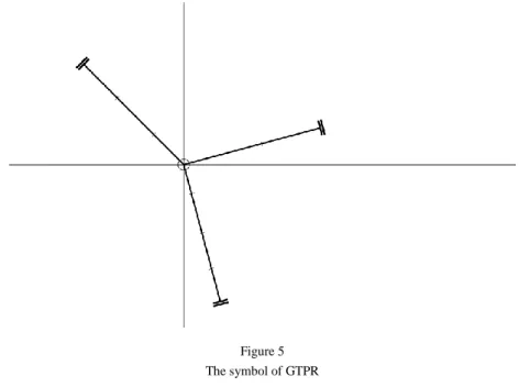
Figure 5 The symbol of GTPR
To symbolize the GTPR we use a pattern given in Figure 5.
J. Somló General Triangle Parallel Robot (GTPR) Basic Features of a New Robot Type - Kinematics and related Application Issues
3.2 Inverse Transformation for the GTPR
For the inverse transformation of GTPR the same approach can be used as for Delta robot above.
Let us analyse the basic features of GTPRs.
The goal of the actions is to change the working point positions as required.
This is given by the coordinates of vector W.
The components of these vectors are:
Wx=x; Wy=y; Wz=z The coordinate system origin is O.
That is: Ox=Oy=Oz=0
At the given arrangement we consider motions where the z coordinates of motions are negative. That is, we consider motions in the lover half space.
Aj, Bj (j=1, 2, 3) are points on the driving arms. The j indicates the proper arm.
C1, C2, C3 are the edge points of the working triangle.
Aj, Bj, C1, C2, C3 are vectors is x, y, z space We use for the coordinates of these vectors:
Ajx, Ajy, Ajz, Bjx, Bjy, Bjz, (j=1, 2, 3).
C1x, C1y, C1z; C2x, C2y, C2z; C3x, C3y, C3z As it was mentioned:
r1, r2, r3, s1, s2, s3 for given GTPR are given, as well as, the parallel mechanism bar lengths g1, g2, g3.
The determination of the robots also includes the α1, α2, α3 values.
Using the distance operator, we have:
D(B1,C1)=g1 D(B2,C2)=g2 D(B3,C3)=g3
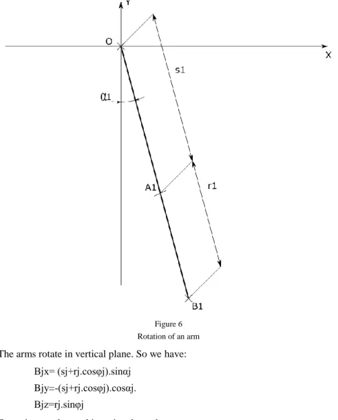
Figure 6 shows how an arm moves. It is shown how a rotating centre point A1 is allocated. We consider it as a point of the basic triangle.
Figure 6 Rotation of an arm The arms rotate in vertical plane. So we have:
Bjx= (sj+rj.cosφj).sinαj Bjy=-(sj+rj.cosφj).cosαj.
Bjz=rj.sinφj
For points on the working triangle we have:
C1x= x+ps1sinα1 C1y= y-ps1cosα1
C1z=z
Similarly:
C2x=x+ps2sinα2 C2y=y-ps2cosα2 C2z=z
J. Somló General Triangle Parallel Robot (GTPR) Basic Features of a New Robot Type - Kinematics and related Application Issues
and
C3x=x+ps3sinα3 C3y=y-ps3cosα3 C3z=z
According to the above we have:
D(Bj,Cj)=gj (j=1, 2, 3) That is
gj2=[(sj+rjcosφj).sinαj-( x+psisinαj)]2+[-(sj+rjcosφj)sinαj-
-(y-p.s1cosαj)]2+(rjsinφj-z)2 (3) Rearranging Equation (3) we get:
[Uj+rjsinαjcosφj]2+[Vj+rjcosαjcosφj]2+(rjsinφj-z)2=gj2 (4) Where:
Uj=sjsinαj-x-psjsinαj Vj=-sjcosαj-y-psjcosαj Performing the operation, we get:
Uj2 +Vj2 +z2 + (2Ujsinαj+2Vjcosαj)cosφj-2rjzsinφj+rj2 cos2 αjcos2 φj+
+rj2 sin2 φj=gj2 (5) j=1, 2, 3
Equation (5) may be solved with suitable nonlinear problem solving methods and software.
The obtained results give the inverse transformation and make possible to realize the required motions.
In the given case a simpler way is possible, too.
The allocation of robots in world coordinate systems is free. So, it is always possible to choose α1=0.
This causes that the second order terms of trigonometrical functions in Equation (5) are eliminated, instead of second order trigonometrical expressions in the equation, rj2 term appear.
In this case Uj=-x
Vj=-sj-y-psj=-y+(1+p)sj Equation (5) becomes:
2Vjcosφj-rjzsinφj+Vj2 +z2 +rj2 –gj2 =0 (6)
Equation (6) can be solved as Williams [9] proposed (see: Equation (2)) In Equation (2)
Ei =2Vj Fi =-rjz
Gi =Vj2 +z2 +rj2 –gj2
Transforming input values to get φ2 and φ3
Solving Equation (6) we get the inverse transformation values for arm 1.
This is φ1.
Now, let us outline how the solutions for the other 2 arm may be obtained.
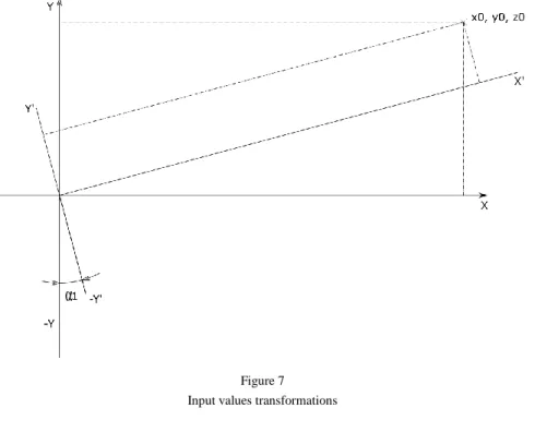
Let us consider Figure 7. It is very easy to recognize that for an arm allocated in a plane having α2, α3 allocation angle the only difference in determining φ2, φ3 is that the relative position of x, y, z is different than for the first arm.
Let the task is to realize:
x= x0, y=y0, z=z0
Let us consider Figure 7. Perform the following transformations for the second arm:
Figure 7 Input values transformations
J. Somló General Triangle Parallel Robot (GTPR) Basic Features of a New Robot Type - Kinematics and related Application Issues
x = x1 = x0cosα2 +y0 sinα2
y = y1 = y0cosα2 -x0 sinα2 (7) z = z1 =z0
Substituting (7), solving (6) we can determine φ2 exactly in the way as it was in the case of α1.
The same is valid when α3 figures instead of α2.
In this way we have got a model for the determination of φ2. φ3.
The inverse transformation problem is solved.
3.2 Direct Transformation for the GTPR
The solution of inverse transformation is the basic task for working actions realization for any robot. For GTPR it may be solved as outlined above.
Sometimes, for example, in analyse of force relations direct transformation, is needed, too.
Solving the direct transformation task the following idea may be used.
Let us consider Figure 8. This Figure is for Delta robot but exactly the same approach is possible for GTPR. We determine so called virtual spheres centre points in the following way. From vectors B1, B2, B3. we extract vectors parallel with C1,OW; C2,OW; C3,OW of the same length. We got the central points of virtual spheres (B1v, B2v, B3v). Spheres with radiuses g1,g2, g3 with centres in B1v,B2v, B3v meet in one point. This is x, y, z.
For any φ1,φ 2, φ3 point from the equations of the three spheres the unique x, y, z value can be determined. This is the solution of the direct kinematics problem.
More about the solution of tree sphere intersection problem may be found in [9].
We determine the so-called virtual spheres centre points in the following way.
Formalizing the above, we introduce in point Bj (j=1, 2, 3) vectors parallel with OWC1, OWC2, OWC3 respectively.
Bjvx=(sj+rjcosφj-psj)sinαj
Bjvy=((sj+rjcosφj-psj)cosαj (8) Bjvz=rjsinφj
Having this centre points three spheres equations can be described:
(x-Bjvx)2 +(y-Bjvy)2 +(z-Bjvz)2 =gj2 (9) j=1, 2, 3
Figure 8
Virtual points for direct transformation
At given φ1, φ2, φ3 values the terms in Equations (9) are given quantities. The three spheres meet only in one x, y, z point.
The determination of this point gives the solution of the inverse transformation problem.
Sometimes this problem is named “The Three Spheres Intersection” problem.
The solution for this is proposed, for example, in Williams [9].
J. Somló General Triangle Parallel Robot (GTPR) Basic Features of a New Robot Type - Kinematics and related Application Issues
4 Application Examples
4.1 Increase of the Working Space in Different Directions and Grasping Oriented Robots
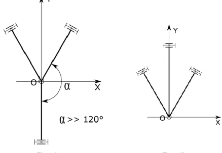
In Figure 9 (a) we show a triangle which results in the increase of the working space in the y direction. These robots have increased workspace in the given directions compared with Delta robots. In Figure 9 (b) we show basic triangle which can be very favourable when grasping tasks are to be solved.
Figure 9a Figure 9b
Extended in y direction work space and grasping tasks solving robots
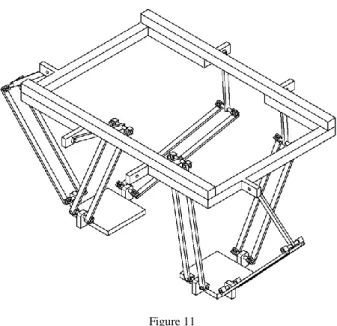
Figure 10 Stepping robot application
Figure 11 Stepping robot
4.2 Stepping Purpose GTPR
In Figure 10 a GTPR schema is given, which can be very useful in stepping robot applications. In Figure 11 a stepping robot is shown realized, using the GTPR shown in Figure 10.
It would be possible to go on with the application examples, but the benefit of introducing GTPR is that instead of only equilateral triangles it opens a very wide horizon, for different applications, with different requirements. The possible variants of these schemas is very high and diverse.
References
[1] Clavel, R. (1990) U.S. Patent No. 4,976,582. Washington, DC: U.S. Patent and Trademark Office
[2] Clavel, R. (1991) Conceptiond’un robot Parallelerapide 4 degre’s de Liberte. PhD thesis EPFL Laussane, Switzerland
[3] Bonev, I. (2014) Delta Parallel Robot, The Story of Success, The Parallel Mechanisms Information Center, (http://www.parallemic.org)
[4] Merlet, J. P. (2012) Parallel robots (Vol. 74) Springer Science & Business Media
[5] Zsombor-Murray, P. J. (2004) Descriptive geometric, kinematicanalysis of Clavel’s “Delta” Robot, Centre of Intelligent Machines, McGill University
J. Somló General Triangle Parallel Robot (GTPR) Basic Features of a New Robot Type - Kinematics and related Application Issues
[6] Zsombor-Murray, P. J. (2009) An improved approach to the kinematics of Clavel’s DELTA robot. IntelligentMachines, McGill University
[7] MarginallyClever Software (2012) Delta robot, Forward/Inverse Kinematics, www.marginallyclever.com/other/samples/fkik-test.html [8] M. Zenkl, Design of Phantom Delta Robot Construction (2017) Budapest,
Diploma Work, Óbuda University
[9] Robert L. Williams II, The Delta Parallel Robot: Kinematics Solutions.
Mechanical Engineering, Ohio University, October 2016
[10] D. Varga, Fantom Delta Robot Precision Measurement (2017) Budapest, Diploma Work, Óbuda University
[11] Somlo J., Paniti I., Rudas I. (2017) Léptető szerkezet humanoid robothoz (Stepping device for humanoid robots) Hungarian Intellectual Property Office, P1600241, Budapest, 2017.10.30.
[12] Somlo J,. Varga D., Zenkl M., Miko B., (2018) The “Phantom” Delta Robot. A New Device for Parallel Robot Investigation. In Acta Polytechnica Hungarica, Vol. 15, No. 4, pp. 143-160; DOI:
10.12700/APH.15.4.2018.4.8
[13] J. Somlo, B. Lantos, P. T. Cat (1997) Advanced Robot Control. Academic Press, Budapest, Hungary, 1997, P.: 425
[14] Shin, McKey (1991) Minimum Cost Trajectory Planning for Industrial Robots. Control Dynamic Systems. Academic Press. pp. 345-403
[15] B. Valcsák (2017) Determination of inverse and direct transformation for parallel robots using geometrical approach. 2017, Budapest, Diploma Work, Óbuda University