Needle Navigation and Catheter Reconstruction for Breast Brachytherapy Using Open Source Software
Thomas A Vaughan
1, Harry Brastianos
2, Tamas Ungi
1, Andras Lasso
1, Conrad Falkson
2, Gabor Fichtinger
11School of Computing, Queen’s University, 25 Union St, Kingston, Ontario, Canada, K7L 2N8; vaughan@cs.queensu.ca; ungi@queensu.ca;
lasso@cs.queensu.ca; gabor@cs.queensu.ca
2Department of Oncology, Queen’s University, 76 Stuart St, Kingston, Ontario, Canada, K7L 2V7; Chariloas.Brastianos@kingstonhsc.ca;
Conrad.Falkson@KingstonHSC.ca
*Authors T Vaughan and H Brastianos contributed equally to the presented work
Abstract: Interstitial breast brachytherapy is a method to deliver radiation therapy directly to the site of cancer. It is a challenging procedure because of issues in localizing the seroma, needles, and catheters within the soft tissue. In this paper we present two open- source technologies based on electromagnetic tracking: a navigation system to help target needles using a tracked needle guide, and software for electromagnetic reconstruction of catheter paths. These technologies were validated phantom studies. We found that the navigation system helped a radiation oncologist to target needles more accurately than under ultrasound guidance (60 needles under each condition, 3.8 vs 3.3 mm placement error, p = 0.04) and that reconstructed catheter paths were accurate within 0.6 mm to those determined on CT scans (144 catheters were compared to the 1.2 mm voxel size of CT scans, p < 0.001). We conclude that these technologies accurately localize anatomy and instruments in our study.
Keywords: breast brachytherapy; electromagnetic reconstruction; catheter reconstruction;
navigation
1 Introduction
Interstitial breast brachytherapy is a radiation therapy procedure to prevent tumor recurrence after surgical removal of breast cancer. Radiation is delivered through catheters inserted in the breast in a pattern to optimize dose distribution. The goal of catheter placement is to insert them with uniform spacing so that radiation can cover the target volume evenly [21]. Failure to achieve adequate dose distribution can result in tissue toxicity or necrosis [25]. Although poor catheter path geometry
can be compensated for, to some extent, by dose optimization [5], the radiation oncologists goal is inserting catheters with uniform spacing throughout the tissue volume. Catheters are positioned by a guiding needle, so needle placements are the key to accurate catheter positions. Interventional radiation oncologists are challenged by several spatial factors that come into play, including the position and orientation of the seroma, the pocket of tissue left behind after tumor excision surgery. The position and orientation of catheters ideally follow a personalized insertion plan. These factors are further amplified by tissue motion and patient breathing [6].
Freehand needle insertions can be augmented by mechanical templates where needle entry, and in some cases exit, points are constrained by holes [16, 25]. A drawback with this approach is that needles can still bend in the tissue. Another drawback is that templates can be large and intrusive. Robots or other mechanical constraints have been used in other organs [14, 15] but they have similar limitations in breast catheter guidance.
Needle insertion has been guided in real-time by a variety of other technologies.
One approach is to use conventional two-dimensional ultrasound [7]. The radiation oncologist uses ultrasound to locate the seroma and observe the trajectory of the needle as it is being inserted. The radiation oncologist can adjust the trajectory of the needle to some extent by manipulating the tissue or by steering the needle [6]. The drawback with ultrasound in general is variable image quality and artefacts. It has been proposed to register and fuse magnetic resonance imaging with two-dimensional ultrasound to help compensate for these issues [27]
but magnetic resonance imaging is not always available. Poulin et al. describe an approach whereby three-dimensional ultrasound is combined with templates [17].
They apply a catheter optimization technique to create a needle insertion plan that optimizes the dose distribution and minimizes the number of needles used. To insert the needles they compared two templates: a generic clinical template where insertions were constrained to existing holes, and a patient-specific template that was custom-designed and rapid prototyped. Catheters implanted with the patient- specific template resulted in inferior dose homogeneity compared to a generic clinical template. Strassman et al. used an electromagnetically-tracked needle holder to guide needle insertions so that they followed a CT-based needle insertion plan [21]. They analyzed the accuracy of guidance in a generic non- anatomical foam phantom. They state that patient immobilization is necessary to use their navigation system. In their clinical experience [20] they report mean needle placement errors between 3.4 mm and 6.4 mm. Magnetic resonance imaging can be combined with specially-designed stylets to track catheters during brachytherapy insertions [2, 4, 26]. The tracked stylet was inserted into each catheter to adjust it according to position data [4]. Tissue damage from the initial placement of the catheter is a concern with this method, and the authors discuss using a set of tracked stylets so that catheters can be inserted to the correct locations on the first try in the future.
To check the placement of needles or catheters during the procedure there are imaging modalities available. Two-dimensional ultrasound and fluoroscopy are conventional methods [11]. Two-dimensional ultrasound provides a cross- sectional image of needle or catheter placement but it can be difficult to see individual needles. Three-dimensional ultrasound features many of the same limitations experienced by two-dimensional ultrasound (e.g. it can be difficult to interpret due in part to imaging artefacts). Fluoroscopy projects the three- dimensional needles to two dimensions and in so doing loses depth information.
Fluoroscopy also exposes the patient and medical team to ionizing radiation.
Electromagnetic reconstruction [1, 29] is a recent method to determine catheter placement. A position sensor is tracked as it is pulled through each catheter. The recorded positions are reconstructed into curves that represent the catheter paths (Figure 1). Electromagnetic reconstruction is an appealing alternative to medical imaging because it circumvents various modality-specific issues, e.g. slice thickness in CT scans, subjective interpretation in ultrasound images. It has recently been evaluated in patients [8].
Even though electromagnetic reconstruction is described and used in numerous papers there is no open-source research platform on which this technology can be readily used. Researchers who wish to use electromagnetic reconstruction must acquire individual hardware components and write custom software to do the reconstruction itself. Most authors in literature reported developing and using proprietary MATLAB (MathWorks, Natick, Massachusetts) software [3, 9, 18, 28].
Figure 1
Electromagnetic reconstruction demonstrated on phantoms. Left, photo of the experimental setup.
Right, virtual image of catheters generated after reconstruction.
We propose two technologies implemented as open-source tools for helping radiation oncologists during brachytherapy. The first is a real-time navigation system for needle insertion in breast brachytherapy that uses a tracked needle guide. The navigation system consists of intraoperative ultrasound-based segmentation of the seroma, an electromagnetically-tracked needle guide, and a bullseye user interface for needle placement. We validate it in a phantom study benchmarking it against conventional ultrasound guidance. The second is a technology for localizing catheter paths through the breast tissue. We describe a fitting algorithm based on moving least squares polynomial fitting.
2 Methods
2.1 Open Source Environment
The PLUS Server application communicates with the spatial tracking drivers and hardware to receive spatial tracking information (positions and orientations) [12].
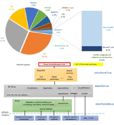
The server component broadcasts the spatial tracking data through the OpenIGTLink protocol to any connected clients [22]. In case of electromagnetic reconstruction, the spatial tracking data includes position data for the sensor that is pulled through each catheter, and optionally position and orientation data for a reference coordinate system. The modules and tools described in this paper were implemented in the 3D Slicer application framework (www.slicer.org) using modules from the SlicerIGT extension [24]. The PLUS Server application and 3D Slicer with its extensions are open-source software that can be used for academic or commercial purposes freely, without any restrictions. Fewer than 5,000 lines of source code describe the specific software for needle navigation and catheter reconstruction – less than 0.01% of the total number of lines of code in the open- source platform (Figure 2, VTK and 3D Slicer alone contain over three million lines of source code).
2.2 Navigated Needle Placement
The proposed navigated brachytherapy begins with a single brachytherapy needle being inserted through the breast and seroma under ultrasound guidance. In this paper, all brachytherapy needles were 20-gauge and featured a bevel (P/N 202-20, Best Medical, Springfield, Virginia).
An electromagnetic tracking fixture is attached to the needle in order to provide a coordinate system for the seroma. The needle can still spin within the tissue, so the seroma is tracked using a spin-invariant tracking method. The seroma shape is segmented on tracked ultrasound similar to how it is done in navigated lumpectomy [23].
Figure 2 Open source code re-use
A needle guide is used to track the trajectory of the brachytherapy needle. The guide is a needle sleeve that restricts needle movement along an axis relative to the sensor (Figure 3). Within the navigation system the Guide coordinate system indicates the position and direction of needle insertion. The guide is calibrated by clamping a needle to it and using pivot and spin methods. A chart of coordinate systems for navigated brachytherapy is provided in Figure 4.
After the first catheter guiding needle insertion, the virtual camera of the navigation view is aligned parallel to the first needle. The intention is that the user can align the guide with the navigation view so that subsequent needles are parallel to the first needle. An insertion plan is drawn on the navigation view and tracked relative to the seroma's coordinate system to help guide needles through and near to the seroma. (Figure 5). The functionality for doing this is implemented in the Viewpoint module from SlicerIGT [24].
Figure 3
Guide. Left, sensor clip and needle sleeve. Right, assembled guide being used on a phantom to insert a brachytherapy needle.
Figure 4
Coordinate systems in navigated brachytherapy
Figure 5
Left, needle insertion plan is drawn on the view according to the first needle's placement. Right, the guide is aligned with the next intended insertion (immediately to the previous needle's right).
2.3 Catheter Path Reconstruction
To address the lack of an open-source tool for catheter path reconstruction, an extension for 3D Slicer called PathReconstruction was implemented. It uses existing functionality from the CollectPoints and MarkupsToModel modules from SlicerIGT [24]. The extension and its dependencies can be downloaded and installed within 3D Slicer using the integrated extension manager. The flow of data is illustrated in Figure 6.
Figure 6
Flow of information in electromagnetic reconstruction
The CollectPoints module contains the functionality for recording a series of positions over time. The MarkupsToModel module contains the functionality for creating curves from point data. In this paper catheter paths are represented using polynomials fit in each of three dimensions. The overall method is similar to that of Poulin et al. [18]. We implemented two polynomial fitting methods and added them to the MarkupsToModel extension. These are global least squares fitting and moving least squares fitting.
Global least squares fitting is faster and intended to be used for previews of catheter paths. A linear solver is used to solve for the coefficients of the polynomial based on the observed coordinates and the distance along the catheter path.
In this paper, distance was modeled by a point’s position along the minimum spanning tree between the two farthest points (start and end points).
Moving least squares fitting is slower and intended for generating accurate catheter paths once all of the data has been collected. For each distance that is resampled along the polynomial, the equation needs to be solved again based on a distance weight.
Distance values that are nearer are weighed higher, while points that are farther are weight lower. In this paper, distances were normalized between 0 and 1, and the weighing function was a Gaussian kernel with standard deviation equal to
8.33% of the length of the catheter and cut off at 99.7%. This was chosen to be similar to the 25% of data that Poulin et al. [18] used for fitting in their algorithm PathReconstruction acts as the front-end for performing point collection (CollectPoints) and curve fitting (MarkupsToModel). All the user needs to do is specify which transform stores the position of the sensor in the catheter, then press a button to start and then to stop recording positions for each catheter. Curves are then automatically created based on the global least squares fitting method. The user has the option of finalizing all catheter shapes by applying moving least squares fitting.
2.4 Navigated Needle Placement Experiment
Phantom models were made of plastisol in the shape of a breast [19, 23]. The plastic was a mixture of 250 mL super-soft plastisol (part number 8228SS, MF- Manufacturing, Fort Worth, Texas), 250 mL plastisol softener (part number 4228S-1, MF-Manufacturing, Fort Worth, Texas), and two teaspoons of cellulose (product number 237132-100G, Sigma-Aldrich, St. Louis, Missouri) for ultrasound contrast. The phantoms contained palpable simulated cylindrical seromas 40 mm in length and 20 mm in diameter. The seromas were cut from a harder sheet of plastisol made from a ratio of 375 mL of regular plastic, 125 mL of plastic hardener, and one teaspoon of calcium sulfate (Sigma-Aldrich, St. Louis, Missouri) for CT contrast.
Spatial tracking and ultrasound imaging was provided by a SonixTouch GPS machine (Analogic Corporation, Peabody, Massachusetts). The tracker was pre- calibrated by the manufacturer. Two guides (Figure 3) were manufactured on a rapid prototyping machine from acrylonitrile butadiene styrene and tracked using Ascension Model 800 sensors (NDI, Waterloo, Ontario). This particular model was designed so that it could clamp onto needles for the purposes of both calibration and tracking the seroma. The guide aperture was 25.1 mm long in this experiment. One guide was for navigation, the other was used to provide a basis for tracking the seroma and the insertion plan. A tracked linear (L14-5/38 GPS) ultrasound probe (Analogic Corporation, Peabody, Massachusetts) was used to segment the seroma. The overall experiment setup is shown in Figure 7.
We measured how accurately the radiation oncologist was able to adhere to a needle insertion plan under control conditions (ultrasound guidance) versus with navigation. For both conditions, the radiation oncologist was asked to implant ten brachytherapy needles through the seroma in three planes (Figure 8). Needles were to be inserted straight with 12 mm spacing between each adjacent pair. This is the same type of pattern used in clinical practice, though the spacing between catheters ranges between 10 mm and 15 mm [30] and the number of planes can vary.
Under ultrasound guidance, the radiation oncologist began by drawing needle insertion points on the phantom using a pen and a ruler (Figure 9). Once the insertion points were drawn, the radiation oncologist inserted each needle under ultrasound guidance. The radiation oncologist referred to both the ultrasound image and to previously-inserted needles to achieve parallel insertions.
Figure 7
Experimental setup for brachytherapy navigation
Figure 8
Intended needle insertion plan in this experiment. Needles are represented by black dots; insertion direction is perpendicular to the image.
Figure 8
Left, a radiation oncologist uses a pen and ruler to draw an insertion plan on a phantom. Right, a plan drawn on a phantom.
To measure adherence to an insertion plan, we compared inserted versus intended needle paths (analogous to catheter paths). To determine inserted paths (paths needles took through tissue) CT scans were acquired of the implanted phantoms.
The needles were segmented on CT and converted to curve representations. The intended paths followed the insertion grid as described earlier. We registered paths based on a landmark registration of path endpoints then an iterative closest point registration. The main outcome measure of this experiment was the distance from each inserted path to its corresponding intended path. After registration, we sampled at 200 uniformly-spaced points the distance from one path to its corresponding planned path. We computed for each path the mean error, the minimum error, and the maximum error. The overall mean and standard deviation for each of these values are reported.
Needle retractions are an indicator of additional tissue damage, so these events were counted during each insertion procedure as a secondary outcome, along with times of performing procedure steps.
2.5 Electromagnetic Reconstruction Experiment
Phantoms were implanted with plastic catheters (Best Medical, Springfield, Virginia) by a radiation oncologist. Catheter paths were determined three times each as per the electromagnetic reconstruction methods described earlier. An Ascension Model 800 sensor provided a reference coordinate system, and a Model 90 sensor was used to collect sample positions within the catheters. A foot-pedal was connected to the navigation computer to allow the radiation oncologist to start and stop reconstructions. The experimental setup is shown in Figure 10.
Electromagnetic reconstruction was performed in locations where implantations occurred in patients. To measure the accuracy of electromagnetic reconstruction, we measured the distance from each reconstructed path to a corresponding ground truth path. The ground truth catheter paths were generated from segmented CT scans of the phantoms. CT scans were acquired using a Brilliance Big Bore
scanner (Philips, Amsterdam, Netherlands). We measured path error as per the method described in the previous section. The amount of time taken for catheter path reconstruction is also reported.
Figure 10
Experimental setup for electromagnetic reconstruction
3 Results
3.1 Navigated Needle Placement
Overall statistics for needle placement are reported in Table 1 for phantoms, and Table 2 for needles. There was a statistically significant improvement in mean error for navigation over ultrasound-guidance (p = 0.04 using one-tailed Mann- Whitney U-test). There was also a statistically significant improvement in minimum error for navigation over ultrasound guidance (p = 0.001 using one- tailed Mann-Whitney U-test). There was a non-significant statistical trend toward longer procedure time when using navigation versus ultrasound guidance (p = 0.09). Testing on the other variables failed to show statistical significance or trends (p > 0.10 using one-tailed Mann-Whitney U-test).
The needle placements are shown in Figure 11. Needle paths were observed to diverge as depth (in the medial direction) increased. Medial perspectives are shown to highlight the difference between inserted and intended paths.
Boxplots of mean error for each catheter are shown in Figure 12.
The amount of time taken during the different tasks are presented in Table 3.
Table 1
Overall statistics in needle insertion for six phantoms. Standard deviations indicated with ±.
Method Number of retractions Time (s)
Ultrasound-guided 1.5 ± 1.6 586 ± 206
Navigated 1.2 ± 1.9 732 ± 199
Table 2
Overall statistics for sixty needle insertions for each of two methods. Standard deviations indicated with ±.
Method Mean
error (mm)
Minimum error (mm)
Maximum error (mm)
Angle difference (°) Ultrasound-guided 3.8 ± 1.8 1.8 ± 1.3 6.9 ± 3.5 3.9 ± 2.1
Navigated 3.3 ± 1.6 1.1 ± 0.9 6.4 ± 3.6 3.8 ± 2.2
Figure 11
Medial perspective screenshots in 3D Slicer showing the locations of inserted paths (magenta) vs intended paths (green). As a reference for distances, catheters are rendered with a radius of 2 mm, ideal
paths are spaced 12 mm apart, and catheters run 120 mm long.
Figure 12
Boxplot of mean errors (per catheter) for ultrasound-guidance and navigation. Each column represents sixty samples.
Table 3
Time in seconds spent on each task in needle insertions for six phantoms under each method. Standard deviations indicated with ±.
Method First Needle Sensor Attachment
Ultrasound Segmentation
Planning Insertions Ultrasound-
guided
65 ± 7 N/A N/A 129 ± 32 391 ± 178
Navigated 58 ± 15 19 ± 5 124 ± 22 45 ± 9 485 ± 176
3.2 Electromagnetic Reconstruction
Upon analyzing the data, we observed that one subset of reconstructions was accurate and another subset was not. The accuracy of reconstruction appeared to depend on whether the experiment was conducted in the location called "Room 1"
or "Room 2". There was a statistically significant difference in the mean reconstruction error between the locations (Table 4, p < 0.001 using one-tailed Mann-Whitney U-test). Results on accuracy are considered separately for these two locations. This section focuses mainly on results from "Room 2" for reasons given in the discussion.
The mean reconstruction error in Room 2 was 0.6 mm and statistically significantly lower than the voxel size of the CT scans (voxel size = 1.2 mm, p <
0.001 using one-tailed sign test). Images of reconstructions from 3D Slicer are shown in Figure 13. The distribution of mean errors is shown as a boxplot in Figure 14, and the distribution of individual point errors is shown as a histogram in Figure 15. The farthest any single point on a reconstructed path was from its corresponding ground truth was 2.1 mm. There was no statistically significant
correlation between the number of sample positions and the mean error for catheters (p = 0.84 using Spearman rank correlation).
In Room 1 the mean reconstruction accuracy was 2.0 mm and statistically significantly higher than the voxel size of the CT scans (voxel size = 1.2 mm, p <
0.001 using one-tailed sign test).
Electromagnetic reconstruction times were recorded for each of 71 catheters three times each for a total of 213 reconstructions. The mean time per catheter was 22 seconds with a standard deviation of 10 seconds. On average 14 seconds were spent inserting the wire into the catheter, and 8 seconds were taken to pull the sensor out and collect position data.
Table 4
Accuracy of electromagnetic reconstruction in phantoms. Standard deviations indicated with ±.
Location Number of
phantoms
Mean of mean errors (mm)
Mean of
minimum errors (mm)
Mean of
maximum errors (mm)
Room 1 7 2.0 ± 1.2 0.7 ± 0.8 4.5 ± 2.8
Room 2 5 0.6 ± 0.2 0.2 ± 0.2 1.1 ± 0.3
Figure 13
Medial perspective screenshots in 3D Slicer showing reconstructed paths (magenta) vs ground truth (green) for phantoms in Room 2. As a reference for distances, catheters are rendered with a radius of 2
mm.
Figure 14
Boxplot of mean errors (per catheter) for electromagnetic reconstructions versus ground truth. Only data from Room 2 are shown.
Figure 15
Histogram of individual point errors for electromagnetic reconstructions versus ground truth. Only data from Room 2 are shown.
4 Discussion
From the experiment in needle insertions, it appeared as though navigation helped the radiation oncologist to adhere to an insertion plan. This result does not seem to be explained by the angle of needle insertion, which was roughly equal between both experimental conditions (Table 2). Rather there appeared to be an improvement in the minimum distance between the inserted and intended paths.
This could suggest that the insertion point was closer to the ideal grid. Future work will evaluate the effect of improved needle placement accuracy on dosage distribution.
There are a few limitations to the navigation method under study. Firstly, the seroma could change shape over the course of navigation due to swelling. The seroma should be checked on ultrasound periodically to ensure that the segmentation shape is still valid. Brachytherapy needles are metallic so they may interfere with the magnetic field used by the electromagnetic tracker. Prior work has found brachytherapy needles to affect positional accuracy of electromagnetic measurements by less than 0.1 mm [21]. Although the tracker is affected by magnetic field distortion, the results measure accuracy compared to a CT image which should not be affected. The needle can still bend within the tissue. It may be possible in the future to embed a sensor in the needle tip or stylet and measure such deviations from that trajectory.
There were fewer needle retractions when using navigation compared to ultrasound guidance. The small numbers make it difficult to draw conclusions regarding retractions in this experiment.
Table 3 shows how much time was spent in each task. The needle insertions took more time when using navigation, likely due to the radiation oncologist consulting both ultrasound and the navigation display. The planning step was shorter for navigation than for ultrasound guidance, likely because planning consisted of a few button clicks on a computer rather than measuring and drawing each needle insertion point on the phantom.
Electromagnetic reconstruction is now available as part of an open-source research platform. It can be downloaded and run on different operating systems, and it can be used to create reconstructions on-line (as data is being collected).
The software we used to analyze the data and generate the results presented in this paper is also included as a module called PathVerification. This may help to enable future comparative and collaborative studies.
For the electromagnetic reconstruction experiment we split data into two groups:
reconstructions that occurred in Room 1 and those that occurred in Room 2.
From electromagnetic reconstructions in Room 2 the error compared to ground truth was less than the voxel size of the CT scans. We could not generate a more precise ground truth to compare against. Accuracy was as high as can be measured given the ground truth that was available.
From electromagnetic reconstructions in Room 1 the error compared to ground truth was more than the voxel size of the CT scans.
There was a difference in accuracy of reconstructions conducted in these rooms.
This was likely due to magnetic field distortion caused by the nearby CT machines similar to those seen by Maier-Hein et al. [13]. Although reconstructions all occurred in the same relative location on the patient table in both CT scanners, the tables themselves may have contained different components. This result emphasizes that magnetic field distortion can vary even between similar locations.
It should never be assumed that two similar locations have similar effects on magnetic field distortion.
Assuming the error was caused by magnetic field distortion, there are at least two options to improve accuracy: 1) using a tracker configuration that includes magnetic shielding (e.g. planar field generator [13]), and 2) characterizing and compensating for the magnetic field distortion [10] prior to electromagnetic reconstruction. These could be good directions for future investigative work.
Our experiment suggested that electromagnetic reconstruction takes around 22 seconds per catheter. This is comparable to the clinical experience of Kellermeier et al. who reported an average of 5 seconds for point collection and 18 seconds for transition between catheters.
Conclusions
We have presented two technologies - a navigation system for brachytherapy needle insertion, that uses a tracked needle guide and an implementation for electromagnetic reconstruction, using an open-source research platform. In a phantom experiment, needles inserted with navigation adhered better to a grid plan, over those inserted under ultrasound-guidance only. We showed that electromagnetic reconstruction can be accurate within 1.2 mm of a CT-based, ground truth in phantoms, depending on the environment. The software for electromagnetic reconstruction is now available, as part of an open-source research platform.
Acknowledgements
Gabor Fichtinger is supported as a Canada Research Chair in Computer-Integrated Surgery. This work was funded, in part, by NIH/NIBIB and NIH/NIGMS (via grant 1R01EB021396-01A1 - Slicer+PLUS: Point-of-Care Ultrasound) and by CANARIE’s Research Software Program. Financial support was received from the Southeastern Ontario Academic Medical Association (SEAMO), Educational Innovation and Research Fund. Thomas Vaughan was funded by Ontario Graduate Scholarships, a Walter C. Sumner Memorial Fellowship, and an Alexander Graham Bell Canada Graduate Scholarship.
References
[1] C Bert, M Kellermeier, and K Tanderup. Electromagnetic tracking for treatment verification in interstitial brachytherapy. Journal of Contemporary Brachytherapy, 8(5):448-453, 2016
[2] Y Chen, W Wang, EJ Schmidt, K-W Kwok, AN Viswanathan, R Cormack, and ZYH Tse. Design and fabrication of mr-tracked metallic stylet for gynecologic brachytherapy. IEEE/ASME transactions on mechatronics: a joint publication of the IEEE Industrial Electronics Society and the ASME Dynamic Systems and Control Division, 21(2):956, 2016
[3] AL Damato, AN Viswanathan, SM Don, JL Hansen, and RA Cormack. A system to use electromagnetic tracking for the quality assurance of brachytherapy catheter digitization. Medical Physics, 41(10):101702, 2014 [4] J de Arcos, EJ Schmidt, W Wang, J Tokuda, K Vij, RT Seethamraju, AL
Damato, CL Dumoulin, RA Cormack, and AN Viswanathan. Prospective clinical implementation of a novel magnetic resonance tracking device for real-timebrachytherapy catheter positioning. International Journal of Radiation Oncology Biology Physics, 99(3):618-626, 2017
[5] L de Boeck, J Beliën, and W Egyed. Dose optimization in high-dose-rate brachytherapy: a literature review of quantitative models from 1990 to 2010. Operations Research for Health Care, 3(2):80-90, 2014
[6] TL de Jong, NJ van de Berg, L Tas, A Moelker, J Dankelman, and JJ van den Dobbelsteen. Needle placement errors: do we need steerable needles in interventional radiology? Medical devices (Auckland, NZ), 11:259, 2018 [7] DA DeBiose, EM Horwitz, AA Martinez, GK Edmundson, PY Chen, GS
Gustafson, B Madrazo, K Wimbish, E Mele, and FA Vicini. The use of ultrasonography in the localization of the lumpectomy cavity for interstitial brachytherapy of the breast. International Journal of Radiation Oncology Biology Physics, 38(4):755-759, 1997
[8] M Kellermeier, R Fietkau, V Strnad, and C Bert. Assessment of the implant geometry in fractionated interstitial hdr breast brachytherapy using an electro- magnetic tracking system. Brachytherapy, 17(1):94-102, 2018 [9] M Kellermeier, J Herbolzheimer, S Kreppner, M Lotter, V Strnad, and C
Bert. Electromagnetic tracking (emt) technology for improved treatment quality assurance in interstitial brachytherapy. Journal of applied clinical medical Physics, 18(1):211-222, 2017
[10] VV Kindratenko. A survey of electromagnetic position tracker calibration techniques. Virtual Reality, 5(3):169-182, 2000
[11] RR Kuske. Breast brachytherapy. Hematology/Oncology Clinics, 13(3):543-558, 1999
[12] A Lasso, T Heffter, A Rankin, C Pinter, T Ungi, and G Fichtinger. Plus:
open-source toolkit for ultrasound-guided intervention systems. IEEE Transactions on Biomedical Engineering, 61(10):2527-2537, 2014
[13] L Maier-Hein, AM Franz, W Birkfellner, J Hummel, I Gergel, I Wegner, and H-P Meinzer. Standardized assessment of new electromagnetic field generators in an interventional radiology setting. Medical Physics, 39(6Part1):3424-3434, 2012
[14] MA Meltsner, NJ Ferrier, and BR Thomadsen. Observations on rotating needle insertions using a brachytherapy robot. Physics in Medicine &
Biology, 52(19):6027-6037, 2007
[15] IPI Pappas, P Ryan, P Cossmann, J Kowal, B Borgeson, and M Caversaccio. Improved targeting device and computer navigation for accurate placement of brachytherapy needles. Medical Physics, 32(6Part1):1796-1801, 2005
[16] A Pompeu-Robinson, M Kunz, CB Falkson, LJ Schreiner, CP Joshi, and G Fichtinger. Immobilization and catheter guidance for breast brachytherapy.
International Journal of Computer Assisted Radiology and Surgery, 7(1):65-72, 2012
[17] E Poulin, L Gardi, A Fenster, J Pouliot, and L Beaulieu. Towards real-time 3d ultrasound planning and personalized 3d printing for breast hdr brachytherapy treatment. Radiotherapy and Oncology, 114(3):335-338, 2015
[18] E Poulin, E Racine, D Binnekamp, and L Beaulieu. Fast, automatic, and accurate catheter reconstruction in hdr brachytherapy using an electromagnetic 3d tracking system. Medical Physics, 42(3):1227-1232, 2015
[19] A Samani, J Bishop, C Luginbuhl, and DB Plewes. Measuring the elastic modulus of ex vivo small tissue samples. Physics in Medicine and Biology, 48(14):2183-2198, 2003
[20] G Strassmann, R Heyd, R Cabillic-Engenhart, C Kolotas, S Walter, G Sakas, D Richter, and N Zamboglou. Accuracy of 3-d needle navigation in interstitial brachytherapy in various body regions. Strahlentherapie und Onkologie, 178(11):644-647, 2002
[21] G Strassmann, C Kolotas, R Heyd, S Walter, D Baltas, T Martin, H Vogt, G Ioannidis, G Sakas, and N Zamboglou. Navigation system for interstitial brachytherapy. Radiotherapy and Oncology, 56(1):49-57, 2000
[22] J Tokuda, GS Fischer, X Papademetris, Z Yaniv, L Ibanez, P Cheng, H Liu, J Blevins, J Arata, AJ Golby, T Kapur, S Pieper, EC Burdette, G Fichtinger, CM Tempany, and N Hata. Openigtlink: an open network protocol for image-guided therapy environment. The International Journal of Medical Robotics and Computer Assisted Surgery, 5(4):423-434, 2009
[23] T Ungi, G Gauvin, A Lasso, CT Yeo, P Pezeshki, T Vaughan, K Carter, J Rudan, CJ Engel, and G Fichtinger. Navigated breast tumor excision using electromagnetically tracked ultrasound and surgical instruments. IEEE Transactions on Biomedical Engineering, 63(3):600-606, 2016
[24] T Ungi, A Lasso, G Fichtinger. Open-source platforms for navigated image-guided interventions. Medical Image Analysis, 33:181-186, 2016 [25] FA Vicini, DA Jaffray, EM Horwitz, GK Edmundson, DA DeBiose, VR
Kini, and AA Martinez. Implementation of 3d-virtual brachytherapy in the management of breast cancer: a description of a new method of interstitial
brachytherapy. International Journal of Radiation Oncology Biology Physics, 40(3):629-635, 1998
[26] DE Wazer, S Kaufman, L Cuttino, T DiPetrillo, and Douglas W Arthur.
Accelerated partial breast irradiation: an analysis of variables associated with late toxicity and long-term cosmetic outcome after high-dose-rate interstitial brachytherapy. International Journal of Radiation Oncology Biology Physics, 64(2):489-495, 2006
[27] S Zhang, S Jiang, Z Yang, and R Liu. 2d ultrasound and 3d mr image registration of the prostate for brachytherapy surgical navigation. Medicine, 94(40), 2015
[28] J Zhou, E Sebastian, V Mangona, and D Yan. Real-time catheter tracking for high-dose-rate prostate brachytherapy using an electromagnetic 3d- guidance device: A preliminary performance study. Medical Physics, 40(2):021716, 2013
[29] J Zhou, L Zamdborg, and E Sebastian. Review of advanced catheter technologies in radiation oncology brachytherapy procedures. Cancer Management and Research, 7:199-211, 2015
[30] RD Zwicker and R Schmidt-Ullrich. Dose uniformity in a planar interstitial implant system. International Journal of Radiation Oncology Biology Physics, 31(1):149-155, 1995