CHAPTER 5
T H E R H E O L O G Y O F P R I N T I N G I N K S A. C. Zettlemoyer and Raymond R. Myers
I. The Role of Printing Inks 145 II. Rheological Requirements of Printing Inks 146
III. Ink Production 147 1. Premixing 147 2. Roll Milling 149 IV. Printing 152
1. Fountain Phase 152 2. Distribution Phase 153 3. Transfer Phase 154 4. Penetration Phase 156 V. Viscometric Study of Printing Inks 157
1. Theoretical Background 157 a. Printing Ink Flow Behavior 157 2. Instruments and Measurement 159 3. Status of the Viscometric Approach in Ink Rheology 162
4. The Mechanisms of Anomalous Viscosity in Inks 163
VI. Tack and Related Phenomena 167 1. The Nature of the Splitting Ink Film 167
2. Force Analysis of Tack 168 3. Instrumentation 169 4. Cohesive Strength of Liquids and Dispersions 172
5. The Rheology of Film Application by Rolls 176
Nomenclature 187 I. The Role of Printing Inks
In the production of the printed page, an ink meets a remarkable num- ber of rheological requirements. Poured or scraped from the can into the press fountain, it must feed properly onto the fountain roller; distribute, transfer, and suffer structural breakdown over some twenty rollers in the distributing system; cover the printing form adequately without filling in fine half tones in pictures; transfer the message to the paper without serious squash out yet with no unprinted areas in solids; and then it must set on the porous paper sufficiently fast to prevent offset on rollers or paper.
All this must be accomplished to supply the web of paper, moving through the press at speeds up to 25 miles per hour, with about 20 pounds of ink per ten inch page width to print 90,000 copies. In a few seconds, the ink is
145
compressed, stretched, sheared, fractured and kissed, and finally when it meets the paper, it is transferred and set-dried in a fraction of a second.
The complexity of this problem is multiplied by the variety of types of printing and of printed matter. From postage stamps to packages and from breadwraps to books, each ink is adapted to one or more of the different types of printing: gravure with indented printing plates, lithographic with work and nonwork areas at roughly the same level, letterpress with raised type, and flexographic with raised rubber plates. A host of variations in these processes and in types of presses cause further differences in rheologi- cal requirements of the various inks employed.
Printing inks constitute 2 % of the dollar volume of the nation's fourth ranking industry. They are both the keystone and the common denominator of the graphic arts. Outside of the esthetic appeal that one ink may have over another, the chief means of judging the quality of an ink is by its flow properties; as a consequence, printing ink rheology is closely identi- fied with its technology.
II. Rheological Requirements of Printing Inks
Practically all printing inks are suspensions of solid pigment particles in complex vehicles. In recent years, the traditional oleoresinous oil-based vehicles have been displaced percentagewise by the invasion of heatset inks based on resins dissolved in petroleum solvents, flexographic inks based on resins in alcohol, and steamset inks based on resins in glycols. Latexes appear to be headed toward limited use in the field; plastisols have also been considered.
Printing inks are usually pseudoplastic and possess a stress-versus-shear rate curve which is essentially linear only in the range of shear rates from 50 to 500 sec.- 1; below this range a decided curvature toward the origin is encountered. As a consequence they seldom can be characterized by a single parameter such as viscosity, except under conditions of high shear or when bracketing a viscosity range. Broad ranges of viscosity and of pigment concentrations are presented in Table I.
TABLE I
VISCOSITIES OF PRINTING INKS
Types Per cent pigment Viscosity, poises
Gravure 10-30 0.5-10
Flexographic 10-40 1-100 Letterpress 20-80 10-500
Newsink 8-12 2-10
Lithographic 20-80 100-800
T H E R H E O L O G Y OF P R I N T I N G I N K S 1 4 7
Printing inks are probably the most precisely controlled commercial solid-in-liquid dispersions. To achieve adequate reduction of pigment agglomerates to below 2 μ for essentially all particles present, inks are usually manufactured, or at least finished, on a three-roll mill. But whether dispersed in a colloid mill, ball mill, or roll mill, rheological demands must be met if the process is to be most efficient. In fact, the rheology of printing inks begins in the premixer, where the pigment is first wetted by vehicle.
The rheological requirements of a printing ink will be followed through the manufacturing stages starting with the most commonly used change- can premixer, followed by the three-roll mill, and progressing through the fountain, distribution, transfer, and penetration phases of letterpress printing.
III. Ink Production
1. P R E M I X I N G
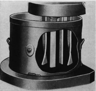
The change-can or pony mixer is used to effect initial blending of the pigments and the vehicle. A typical mixer is illustrated in Fig. 1 where the can has been cut away to show the shape and direction of motion of the mixing blade. The usual procedure is to introduce the vehicle and part of the pigments and to add additional pigment as the wetting progresses in order to minimize dusting.
FIG. 1. Typical change-can mixer used for blending pigments with vehicles
An "intensive mixing" procedure has been developed by Hoback1 and described by the New York Paint Production Club.2 Accordingly, a limited amount of vehicle is used with all the pigment so that wetting down occurs in about 2 min. and at a high level of viscosity. After subsidence or "break"
of the paste, the additional vehicle is added to give the mixture a proper consistency in preparation for the roller mill. At the higher viscosity in
"intensive mixing," air is largely eliminated, the pigment is more finely dispersed, and lumps are eliminated.3
Rheological properties are changing constantly during the premix operation; generally, viscosity increases at the start. The most suitable conditions for each type of pigment-vehicle combination must be deter- mined empirically; and as a consequence, there is need for a more careful elucidation and control of the process. No satisfactory method has been developed for deciding that the premixing is completed, such as the method of sediment volumes which is employed in dispersions made from low viscosity vehicles.
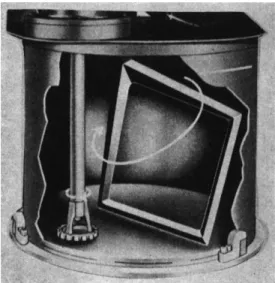
The "consistency" or rheological nature of the ink usually determines which is the most suitable mixer to employ. For relatively low viscosity the high speed turbine type of mixer is frequently used. In this mixer, high local shear rates accomplish dispersion; and the pumping action of the impeller circulates the fluid, bringing all portions of the batch into the high energy zone. For high viscosity and extremely short inks, mixers must employ a positive displacement shearing action where all portions of the batch are brought into the agitation zone through rotation of the mixer tub, through eccentric motion of the impeller shaft, or both. A re- cently developed angular mixer, Fig. 2, has combined features of both high speed impeller shear and positive displacement mixing action.4
Rheological properties influence the effectiveness of the mixing opera- tion and determine the mixer power consumption. Metzner5 has shown that it is possible to employ a generalized Reynolds number for pseudo- plastic materials obeying the relationship that stress = constant X (shear rate)71, to correlate power consumption with turbine type mixer size and speed. Pseudoplastic flow properties tend to stabilize the flow pattern, and
1 W. H. Hoback, Practical Aspects of Pigment Dispersion, Offic. Dig. Federation Paint & Varnish Production Clubs 3 1 6 , 255-297 (1951).
2 New York Paint Production Club, Offic. Dig. Federation Paint & Varnish Pro- duction Clubs 3 1 1 , 977-1000, December (1950).
3 This subject is covered in National Printing Ink Research Institute Project Report No. 2, August 1946 on the Beken Mixer. American representatives are Bramley Machinery Corp., Edgewater, New Jersey.
4 Troy Engine and Machine Company, Troy, Pennsylvania, describes this mixer in Catalog GP-50.
5 A. B. Metzner and R. E. Otto, AIChE Journal, 3 (1), 3 (March, 1957).
T H E R H E O L O G Y OF P R I N T I N G INKS 149
FIG. 2. The Troy angular mixer which combines high speed shear with thorough material turnover.
pseudoplastic fluids require higher levels of the Reynolds number to achieve complete turbulence than do Newtonian fluids.
2. R O L L M I L L I N G
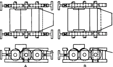
Most inks are finished on a roll mill where the fluid is subjected to increasingly higher rates of fluid shear between successive rolls operating at higher speeds and closer clearances. The three-roll mill having a feed nip and an apron nip is most commonly used. The clearance between the rolls depends on a number of variables, especially on ink viscosity and force on the rolls. A clearance of 10 μ would correspond to a tight setting in the final or apron nip. In recent years a "floating roll" mill has come into wide usage.6 The design of this type of mill is such that only two points of mill adjustment are required instead of the customary four points. The center roll is self-positioning and self-aligning. Figures 3A and 3B are sche- matic diagrams of conventional and floating roll mill designs.
Little or no crushing of primary pigment particles occurs in the roll mill. Its chief function is to disperse pigment agglomerates through fluid shear and particle-particle attrition. The largest agglomerates are crushed between the rolls, whereas the smaller agglomerates are dispersed mostly by hydraulic shear, which has been estimated to be of the order of magni- tude of 50,000 sec.- 1. It is the largest agglomerates which show up on the commonly used grind gage for estimating the fineness of grind of the
6 L. Maus, W. C. Walker, and A. C. Zettlemoyer, Ind. Eng. Chem. 47, 701 (1955).
A B
FIG. 3. Schematic diagrams of three-roll mills, top and side views. A . Conven- tional type—the center roll is fixed and the two outer rolls are positioned (four point adjustment). B. Floating roll type—the center roll is free to align itself between one fixed and one movable outer roll, thus requiring only two points of adjustment.
1 0 5
ο ο
—
0 2 4 6 8 1 0 1 2 P a s s e s
FIG. 4. Reduction of ink viscosity and fineness of grind with number of passes through a roll mill. Fineness of grind is a measure of maximum particle size.
T H E RHEOLOGY O F PRINTING INKS 151
dispersion.7 Both production rate and fineness of grind appear to be pro- portional to the apron nip clearance in many instances. It has been found that the reduction in viscosity per pass and the decrease in fineness of grind follow a first order rate equation,8 as shown in Fig. 4. There is evi- dence, however, that this is partly due to the fact that reduction in vis- cosity effected by dispersion and by heating on one pass allows the mill to operate at a closer setting on the next pass.
Production rate Ä, in volume per unit time, of a three-roll mill depends on four factors: the quantity of ink Q entering the feed nip, the fractional transfers / and a from slow to fast roll at the feed nip and apron nip, respectively, and the fraction of ink t removed from the apron roll by the take-off knife. The relationship is given by the equation
R = , . Q . (1)
1 — a + at
Q for a given mill is a function of roll speed, force between the rolls, and ink viscosity. The transfer factors a and / appear to depend primarily on roll speed ratio and on ink rheological properties as yet to be elucidated,9
but generally grouped under the term viscoelasticity.
The film leaving the mill nip splits somewhere between the surface of the slow roll and the center of the nip; that is, the split occurs closer to the fast roll than desirable for highest efficiency. Figure 5 shows that the percentage transfer for a variety of commercial inks increases with the
7 W. C. Walker and A. C. Zettlemoyer, Am. Ink Maker 28, 7, 31 (1950).
8 Roughly speaking, —άη/dn = Κη rather than —άη/dt = K.
9 A. Voet, Phys. ώ Colloid Chem. 51, 1037 (1947).
TABLE I I
RELATIONSHIP OF PERCENT TRANSFER TO INK PROPERTIES0
Ink. No. Inkometer reading Viscosity, poises Per cent transfer
3:1 Roll speed ratio
1 4.3 77 78.9
2 4.4 65 79.2
3 5.6 62 80.3
4 7.2 59 82.2
5 11.2 64 87.3
6 14.8 87 90.6
7 16.5 125 92.5
8 19.7 487 94.7
9 26.2 135 97.7
10 30.9 103 98.0
2:1 Roll speed ratio
11 5.6 75.6
3 5.6 62 77.3
12 7.1 75.3
4 7.2 59 78.1
5 11.2 64 83.2
7 16.5 125
8 19.7 487 92.3
13 19.9 412 92.3
14 21.0 124 92.8
15 30.9 125 97.7
α From T. A. Sparta, M.S. Thesis, Lehigh University, Bethlehem, Pennsylvania, October, 1954.
b Model B-45, Roller composition 1C-6513, low speed, 30°C.
reading on an Inkometer which is a two-roll instrument simulating a press, described on page 1 7 0 .
Roll mill productivity can sometimes be increased by additives which increase Inkometer reading and lead to more complete transfer from slow to fast roll. Inkometer reading and the transfer factor generally increase with ink viscosity; the data of Table II show that these empirical values correlate better than does viscosity. In addition to purely mechanical factors such as state of blade wear, blade angle, and blade pressure, take-off knife efficiency depends on ink film thickness and ink viscosity.
IV. Printing
1. F O U N T A I N P H A S E
The first shear of appreciable magnitude encountered by an ink during printing occurs when it leaves the press fountain via the fountain roller.
T H E RHEOLOGY O F PRINTING INKS 153 The chief requirement in this initial phase of printing is that the ink follow the fountain roll and not deplete itself adjacent to the roll which starts it on its way through the press. Correlation between measured rheological properties and behavior does not seem to be completely revealing, but it is known that inks with excess structure perform poorly in the fountain.
Inks with good length, that is, those which readily form threads, will generally behave well in the fountain, whereas short inks often will not properly follow the roll. Length usually correlates with plastic viscosity divided by dynamic yield value:10 A short ink has a high dynamic yield value-plastic viscosity quotient (see page 165); a long ink generally has no recognizable yield value and is characterized by a quotient which approaches zero.
On the other hand, once it has started through the press, an ink with both a high yield value and a high viscosity will function properly. Pre- sumably, the cohesive forces are sufficiently great in such cases to allow the ink to follow the fountain roll.
2. D I S T R I B U T I O N P H A S E
The function of the distributing system of a press is to break down any structure present in the ink and to distribute a uniform film on the form rollers. In this phase the ink is subjected to a discontinuous shear. Voet11
has calculated that the ink is sheared about of the time and that the stresses developed are high (of the order of 10e dynes/cm.2). Although the ink is at rest most of the time, the period of rest is probably less than a second; this time is believed to be too short to allow much structure to develop.
The length of the ink is apparently the rheological property of most importance in the distribution phase. If the ink is too short—e.g., if the formulation is "dry" due to high pigment loading—the ink will not follow the rolls properly, and poor or uneven distribution will result. On the other hand, if the ink is too long, flying or misting may occur. Misting occurs when in the course of splitting, an ink filament necks down at two or more places leaving fragments suspended in the air. High shear rheological properties during the rupture of thin filaments need to be explored to shed light on this problem.
In gravure printing, Bowles12 suggests that inks should be dilatant. If this concept is correct, the ink would stiffen under mechanical action, and
1 0 A. C. Zettlemoyer, W. C. Walker, J. M. Fetsko, and R. R. Myers, Intern. Bull.
Printing and Allied Trades 7 3 , 60 (1956).
1 1 A. Voet, "Ink and Paper in the Printing Process," p. 51. Interscience, New York, 1952.
12 R. F. Bowles, Oil & Colour Chemists' Assoc. 3 3 , 72 (1950).
clean wiping prior to printing could take place on the surface of the intaglio plate. Yet the ink could still be transferred during printing from the recessed areas to the paper, perhaps aided by the absence of high shear at the instant of impression.
It should be recognized that distribution on a roller system and other aspects of ink transfer are little understood and deserve serious analysis.
If organic solvents in combination with resins are chosen haphazardly, fewer than 5% of the combinations will distribute and transfer well on the roller system of a given press. The required combination of wetting and rheological properties has not been delineated sufficiently to permit formulations to be made on a scientific basis.
3. T R A N S F E R P H A S E
From the time the ink leaves the can until the finished print emerges, the treatment of a printing ink can be characterized by the single word, transfer. In the sense used here, the process by which the ink leaves the press is referred to as transfer; the ink is transferred from the plate or rubber blanket to the paper concurrently with a partial drainage of vehicle into the paper, and finally the printed sheet is withdrawn from the plate or blanket. In the transfer to paper, the ink is under high compression followed by high tension. Thus, an ink with a high degree of resistance to deformation or high viscosity is needed. If the viscosity is too low, the ink on halftone dots will be forced out from the center to the sides of the dots and will produce distortion and poor reproduction. When the ink is short, mottling of solid areas will usually tend to be minimized; long filaments will not form. Then less uneven coverage is likely to develop as the shorter filaments subside.
When the printing form is separated from the paper, the ink film is split for the last time. The resistance of the ink film to rapid splitting is called tack, and in this particular transfer the problem of tack becomes most prominent. If the tack of an ink is too great, the paper may be rup- tured before the ink film splits, giving rise to a phenomenon called picking.
In the transfer phase as a whole, the ink should have as high a viscosity as can be obtained, consistent with the requirement that no picking of the paper takes place. Splitting force increases with press speed, therefore more viscous inks can be used at low press speeds than at high speeds. In wet multicolor printing, the tack of an ink is also of importance for proper trapping where the tack of each successive ink must be less than that of the previous one so that the split will always take place in the last-down film.
In the transfer phase of printing on paper, drainage of ink into the pores begins as the impression is made. Since the pores are small and the printing pressures are high (from 100 to 500 lb. per inch of roll width), the ink is
T H E RHEOLOGY OF PRINTING INKS 155
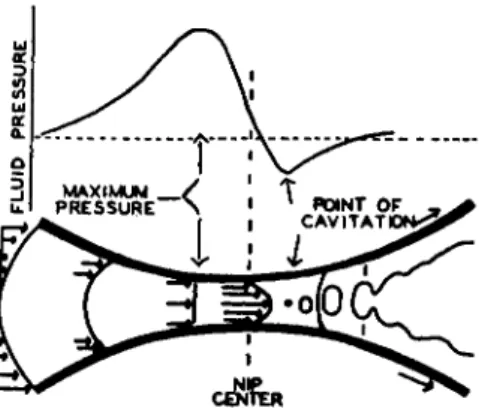
FIG. 6. Pressure and velocity profiles for a Newtonian fluid splitting between two rolls turning at the same speed.
subjected to a high stress. The length of time that this high stress acts is very short so that only partial drainage occurs during this interval, despite the high pressures. In this step, the viscosity of the ink at high shear stresses is more important than its low shear viscosity. It may be noted that the ink might become more concentrated in pigment because of drain- age, and thereby develop increased tack. On nonporous stocks such as cellophane or metals, of course, such drainage cannot occur. When the ink film is sufficiently thick to cover all the depressions, the amount transferred y has been found13 to depend on the ink film thickness χ according to the equation
y = b+fr(z-b) (2) where b is the amount of ink immobilized during the impression and fr is
the fraction of the residual ink film split to the stock. Recently, fr has been found14 to correlate with the ratio of yield value to plastic viscosity. This ratio, considered to be a measure of "shortness," has been thought to be related to fr because little or no shear takes place near the region in the nip between separating rolls where the splitting action takes place.
The flow pattern and pressure distribution15 of an ideal fluid in a roll nip (without slippage) are pictured in Fig. 6. A quite similar situation exists in the nip between plate and paper during printing and between the rolls in a roll mill. No shear takes place at the maximum and minimum in the pressure distribution curve. Cavitation begins near or at the mini- mum, as is explained later. Maximum rate of shear, up to thousands of reciprocal seconds occur near the center of the nip. The high pressure on the entrance side of the nip creates a pumping action so that more fluid passes
1 3 W. C. Walker and J. M. Fetsko, Am. Ink Maker 33, 12, 38 (1955).
14 A. C. Zettlemoyer, R. F . Scarr, W. D. Schaeffer, Τ AGA 9th Ann. Proc. 75 (1957).
1 6 R. E. Gaskell, Trans. Am. Soc. Mech. Engrs. 72, 334 (1950).
through the nip than indicated by the clearance. That the minimum occurs at about zero absolute pressure when a film is split (as opposed to the situation when the rolls are completely immersed) is becoming increasingly clear.16 If the non-Newtonian nature of the ink and penetration into the paper are taken into account, it can be recognized that the flow pattern may be more complicated than that suggested in Fig. 6. According to the picture presented, splitting is initiated where the shear rate is low. For this reason, the low shear data of plastic viscosity and yield point from precision rotational viscometry up to a few hundred reciprocal seconds might be expected to correlate with the fr values from transfer data. In Fig. 7, quite good correlation is indicated for a variety of dispersions between fr and So/U.
Transfer to the paper poses a host of problems, not all of which arise from irregularities in paper surface and quality. One problem in which some headway has been made in recent years is that of wet multicolor trapping and the related phenomenon of picking, where the uses of certain test instruments have been demonstrated.17
4. P E N E T R A T I O N P H A S E
The penetration phase follows the transfer phase and involves the drainage of the vehicle into the pores of the paper. As already mentioned, part of this drainage occurs in the transfer phase under high stresses. Most
1 6 Printing, Packaging and Allied Trades Research Association, Annual Report 1953-1954, p. 26.
17 A. C. Zettlemoyer, C. T. Dickert, W. C. Walker, and R. R. Myers, Preprint booklet, Meeting of Paint, Plastics and Printing Ink Division of the American Chemical Society, Kansas City, Missouri, p. 95, 1954.
T H E RHEOLOGY O F PRINTING INKS 1 5 7 of the penetration phase usually occurs in the first minutes.18 This process proceeds entirely under the stresses induced by capillary action, since those due to the printing pressure are no longer operative. The most fruitful studies of penetration of liquids into paper have been performed by Tol- lenaar.19
Rapid drainage of a vehicle of moderately low viscosity is needed to set the ink sufficiently to permit the print to be handled prior to drying. If the drainage is not rapid enough, sticking or offsetting to the sheet above will occur; however, if the drainage is excessive, insufficient binder will be left in the film to bond the pigment properly, and a "chalky" condition will result. Thus, intermediate rheological properties are required to prevent occurrence of either of these extreme conditions.
In recent years, an interesting combination of rheological properties has enabled the development of a variety of gloss inks, in which the resin has been selected so as to be somewhat insoluble in the remainder of the vehicle and yet to be readily dispersible. During the penetration phase, the discrete particles of resin are left on the surface while some of the vehicle drains into the stock, leaving a smooth and glossy film due to the holdout.
V. Viscometric Study of Printing Inks 1. T H E O R E T I C A L B A C K G R O U N D
a. Printing Ink Flow Behavior
The fundamentals of the rheology of dispersions and the principles of its measurement have been described in detail in Chapter 1 4 , Volume 1, by Frisch and Simha. Rheological concepts for dispersions such as printing inks have developed in a somewhat unusual fashion, however, and require brief mention here.
It is not possible to describe printing ink dispersions by means of a single material constant such as can be done with the continuous phase from which it is made. Nonetheless, the printing ink rheologist must find ways to characterize dispersions by physical constants, and the most significant of these is viscosity. The introduction of solid particles, as for example pigments or extenders, into a vehicle to produce a product of commercial value invariably results in non-Newtonian or anomalous flow behavior. As a result, the flow of an ink is far more difficult to characterize and is less clearly understood than the flow of pure liquids.
18 R. R. Coupe and A. H. Smith, Oil & Colour Chemists' Assoc. 39, 8, 579 (1956).
» D . Tollenaar and G. Blokhuis, Appl. Sei. Research A2 (2), 125 (1950); D. Tol- lenaar, Appl. Sei. Research A3 (6), 451 (1953); D. Tollenaar, Intern. Bull. Printing and Allied Trades 67, 16 (1954); D. Tollenaar and P. Ernst, Technical Association of the Graphic Arts, 8th Proc., 37 (1956).
Einstein20 derived the first equation for calculating the viscosity of a Newtonian suspension from the concentration of pigment. Printing ink systems, however, do not obey the relation between volume concentration and viscosity defined by his equation, nor do they obey strictly any of the known relations in which a single viscosity parameter is employed. Many investigators have worked on extensions of the Einstein equation to take into consideration important factors in ink systems such as particle shape and particle-vehicle interaction,2 1 - 24 particle sediment volume,2 5-26 and particle area.27
Although the basic factors in anomalous flow have long been rec- ognized,2 8-29 only recently has substantial progress been made in elucidating the mechanism involved.30 In the case of dispersions, viscous anomalies stem from two primary causes: particle disturbances such as rotation of clusters, and immobilization of vehicle in interstices of aggregates or on pigment surfaces.
Several workers have attempted the application of rheology to dispersion technology. Among these are Bingham31 who recognized that different dispersions exhibit different anomalies, Green32 who established a basis for industrial utilization of rheological data, Reiner33 who developed a theoretical treatment of sources of anomalies in general which has recently been used34 to advantage in the printing ink field, and Voet and Suriani35 who established a simple relation between relative plastic viscosity and the ratio of pigment to vehicle volume:
log UR = Κφ (3)
UR is the ratio of plastic viscosity of the dispersion to the viscosity of the
2 0 A. Einstein, Ann. Physik 19, 289 (1906); 34, 591 (1911).
21 V. Vand, Nature 155, 364 (1945); Phys. & Colloid Chem. 52 , 277 (1948).
2 2 R. H. Brailey, Preprint booklet, Meeting of Paint, Plastics and Printing Ink Division of the American Chemical Society, New York, 1951.
2 3 E. Guth and R. Simha, Kolloid-Z. 74, 266-75 (1936).
24 A. Voet and L. R. Suriani, Am. Ink Maker 30, 37 (1952).
2 5 J. S. Gourlay, J. Oil & Colour Chemists' Assoc. 34, 385 (1951).
2 6 J. V. Robinson, Trans. Soc. Rheol. 1, 15 (1957).
2 7 A. C. Zettlemoyer and G. W. Lower, / . Colloid Sei. 10, 29 (1955).
2 8 F. R. Eirich, M. Bunzl, and H. Margaretha, Kolloid-Z. 75, 20 (1936); F. R. Eirich and R. Simha, Monatsch. Chem. 71, 67 (1937)
2 9 E. Guth, Kolloid-Z. 74, 147 (1936).
3 0 M. Reiner, "Deformation and Flow." Lewis, London, 1949.
31 E. C. Bingham, "Fluidity and Plasticity." MaGraw-Hill, New York, 1922.
32 H. Green, "Industrial Rheology and Rheological Structures." Wiley, New York, 1949.
3 3 M. Reiner, see reference 30.
34 J. C. Miller, unpublished work.
3 5 A. Voet and L. R. Suriani, J. Colloid Sei. 7 , 1 (1952).
T H E RHEOLOGY OF PRINTING INKS 159 vehicle, and φ is the ratio of pigment volume to vehicle volume. The constant Κ varies from system to system but appears to characterize the rheological behavior of any one dispersion.
2. INSTRUMENTS A N D M E A S U R E M E N T
Theoretically, the ideal viscometer is a parallel plate assembly of infinite area. However, certain compromises must be made in the interests of practicality of design. Hence, the most satisfactory instrument for gathering fundamental data on inks is the precision rotational viscometer.
One of the earliest rotational viscometers was that of Couette,36 modifica- tions of whose design have found their way into the printing ink field in the form of the rotating spindle types. Examples are: (1) the Stormer viscometer37 which enables one to time the descent of a weight attached to a revolving spindle; (2) the Brookfield viscometer whose chief virtue is its portability and whose distinguishing feature is its ability to measure torque directly from the moving spindle; and (3) a more recent design based on the Brookfield principle and called the Drage viscometer.38
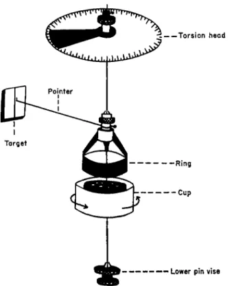
Of far more fundamental import in the study of printing inks have been the rotating cup versions of Couette's viscometer. Green39 designed a rotational viscometer specifically for printing inks which currently is of more than historical value despite the advent of at least two other rotational viscometers which have been used in printing ink rheology. One of these, similar to Greene and designed by Buchdahl et al.,40 is referred to as the Sun precision rotational viscometer; the other, by Myers and Zettlemoyer41 is called the Squibb viscometer, and is shown schematically in Fig. 8.
By means of a completely frictionless torque-measuring suspension, this viscometer has enabled a new region of low shear viscometry to be investi- gated (for example, see page 166).
Although the temperature rise in a rotational viscometer cannot be measured directly in the fluid under study without disturbing the laminar shear, the rise has been demonstrated to be highly significant.4 2'43 This Laboratory was the first to point out that the temperature rise can be 50°C.
at 550 sec.- 1 shear rate in a modern precision rotational viscometer; tem-
3 6 M. Couette, Ann. chim. et phys. 21, 433 (1890).
37 A. J. Stormer, Trans. Am. Ceram. Soc. 11, 597 (1909).
3 8 A. G. Epprecht, F.A.T.I .P.E.C., Compt. rend. 2* Congr., Noordwijk, Holland 1953, p. 125.
3 9 H. Green, Ind. Eng. Chem., Anal. Ed. 14, 576 (1942).
4 0 R. Buchdahl, J. G. Curado, and R. Braddicks, Jr., Rev. Sei. Instr. 18, 168 (1947).
41 R. R. Myers and A. C. Zettlemoyer, SPE Journal 11, 43 (1955), U. S. Patent 2,796,758 (1957).
42 G. W. Lower, W. C. Walker, and A. C. Zettlemoyer, Colloid Sei. 8, 116 (1953).
« R. N. Weltmann and P. W. Kuhns, / . Colloid Sei. 7, 218 (1952).
Lower pîn vise
FIG. 8. Schematic diagram of the Squibb viscometer. Features include no friction torque assembly, annular space for sample to give double shear area, and adjustable head to give null point operation.
perature measurements were made at the sides of the annular space on the cup and on the bob. The best way to define the steps needed to con- trol the temperature is in terms of energy input per unit area per unit time.42 If steps are not taken to control the temperature, the flow curve may be curved in the direction of lower viscosity as the shear rate is in- creased. Ordinary mineral oils, vegetable oils and litho varnishes show no evidence of non-Newtonian behavior when the temperature is properly controlled.
Cone-and-plate attachments can be made for practically any of the existing rotational viscometers. This design is due to Mooney44 and is commercially available. The plate is driven and the cone makes an angle of about 3° with the plate so that the rate of shear is the same at all radii.
The need for only small samples of material, the ease (but not precision) of temperature control, and high shear rates achieved are advantages which have led to current investigations in printing ink rheology.
4 4 M. Mooney and R. H. Ewart, Physics 5, 350 (1934).
T H E RHEOLOGY O F PRINTING INKS 161 Printing inks exhibit the usual viscosity anomalies associated with pseu- doplastics, and in addition they often fail to produce a reproducible stress- shear rate relation. At some critical speed, which depends somewhat on the geometry as well as on the nature of the ink, flow curves often fail completely. The type of hysteresis described by Green is present; but in addition, the untenable situation occurs in which stress actually decreases with increased shear. On reduction of shear, the descending slope appears somewhat uniform, but undoubtedly suffers from slippage or the forma- tion of voids.
An interesting adjunct to rotational viscometry has been used on printing inks by Voet45 who adapted the dielectric constant method of Bruggeman46
to flowing systems. The dielectric constant of a dispersion depends more on the particle shape and the amount of aggregation than on particle size.
For irregular particles the dielectric constant e for the dispersion is related to that of the medium emed by the equation
€ = €m e d( l + 3 / 7 ) (4) The magnitude of the form factor/depends on the orientation of the particle
with respect to the electric field, with the result that e decreases with shear in dispersions of low dielectric solids such as metal powders and carbon blacks, and in general depends on the relative dielectric constants of the medium and the pigment.
The dielectric constant technique, along with thç similar methods of dielectric loss and conductivity, have augmented the value of rotational viscometry as a fundamental instrument in studying dispersions. The importance of agglomeration or flocculation as the pigment concentration is increased has been amply demonstrated by this approach. Of particular interest is the possibility of detecting incipient gel formation or aggregate growth at much lower shear rates than have been studied heretofore.
The empirical flow test of Bowles47 also utilizes a rotational viscometer.
After shearing at a definite rate, the rotation is stopped and the decrease in torque with time is measured. The two arms of the curve obtained have been related to various required properties in the printing operation.
Another interesting use of the rotational viscometer in ink technology has been in the study of rates of thixotropic breakdown of inks at constant rates of shear.48 An attempt to divorce the kinetic aspects of shear break- down as measured by rate studies from the thermodynamic aspects as exemplified by the flow curve has been made by Miller.49 He concluded
4 δ A. Voet, Phys. & Colloid Chem. 51, 5 (1947).
4 6 D . Bruggeman, Ann. Physik 24, 636 (1935).
4 7 R. F. Bowles, Oil & Colour Chemists1 Assoc. 31, 87 (1948); 34, 339 (1952).
48 R. N. Weltmann, Rev. Sei. Instr. 16, 184 (1945).
49 J. C. Miller, unpublished work.
that this approach warrants much more attention than it has received up to the present time. More recent work by Knauss50 indicates that energy input is the proper parameter on which to base breakdown studies, rather than shear rate as usually employed.
Two viscometers of the vibrating reed type have been used in the evalua- tion of printing inks: the Ultra-Viscoson51 and the RCA viscometer.52 Interesting results concerning the thixotropic behavior of inks have been obtained using both of these instruments, but most of the findings have been of a qualitative nature. For example, position-sensitivity of the probe has been used as evidence of pseudoplasticity.
3. STATUS OF T H E VISCOMETRIC A P P R O A C H I N I N K R H E O L O G Y
The basis of the Bingham, Green, and Reiner approaches is the flow curve, which is a representation of stress versus the rate of shear. Valuable correlations of flow curve data with structure parameters have been found.
The correlations have been interpreted in terms of particle shape, particle aggregation, interactions involving the liquid, and the other tenets.5 3 - 55 Such interpretations are the first step toward gaining sufficient insight into the behavior of suspended particles to permit changes of preparation or composition of industrial dispersions to be made in the most logical direc- tion; however, they do not show promise of unfolding the whole story because the viscometric method involves changes in structure as the data are taken. The reason for determining viscosity at various shear rates is not the gathering of data at the shear rates used in printing (which are much higher), but the elucidation of this structure.
The complexities of printing ink flow arise from the fact that inks are concentrated dispersions and also involve problems in the surface chem- istry of pigments. The forces emanating from the surface of the discontin- uous phase of a dispersion, as well as the complex hydrodynamic behavior of concentrated dispersions, give rise to deviations from the behavior pre- dicted by Einstein and require the use of a flow curve as a means of ex- pressing rheological information. The effects listed below not only give rise to correction factors in the original Einstein equation but also result in a variable deviation, for reasons which will become apparent in the mecha- nistic picture about to be presented. This variable generally is manifest as pseudoplasticity (decreased viscosity with increased shear) rather than
6 0 C. J. Knauss, unpublished work.
6 1 W. Roth and S. R. Rich, Appl. Phys. 24, 940 (1953).
6 2 J. G. Woodward, Colloid Sei. 6, 481-91 (1951).
6 3 C. F. Goodeve and G. W. Whitfield, Trans. Faraday Soc. 34, 511 (1938).
6 4 T. H. Hazlehurst and H. A. Neville, J. Phys. Chem. 44, 592 (1940).
6 6 G. B. Moses and I. E. Puddington, Can. J. Chem. 29, 996 (1951).
T H E R H E O L O G Y OF P R I N T I N G I N K S 163 as dilatancy or rheopexy (increased viscosity with increased shear). Only the pseudoplastic case is considered here.
A broad classification of the complex effects which might be encountered in the rheology of dispersions has been made by Reiner:56
(a) Particle-liquid interaction. Included here are bond formation, polariza- tion, induction, and dispersion forces ; the last mentioned are often the most potent of the van der WaaPs attractive forces.57
(b) Particle-particle interaction. The role of the solvent in transmitting residual surface forces from one particle to another is important. The possibility of altering the attraction of one particle for its neighbors has been realized in the established practice of lowering the surface energy of pigments and extenders via coating with polar organic compounds and resins.
(c) Disturbances leading to pseudoplastic behavior. Concavity toward the rate of shear axis will result if the particle is not a sphere or not rigid, for then it can distort or align itself with shear. Four mechanisms have been recognized which account for disturbances of this nature and are discussed in the next section.
The state of subdivision has an enormous effect upon the area of the solid. Since interactions depend upon the extent of the surface as well as on its nature, the effect of fine subdivision on the rheology of suspensions is enormous. One significant effect of particle size is that dilatant systems are formed in highly deflocculated suspensions comprising small solid particles. Because solvent is released on increasing the shear rate, flocculation gives rise to pseudoplasticity and indicates incomplete wetting of the solid by the liquid. More important to the printing process, thixotropy (time dependent viscosity change) often appears in easily flocculated dispersions.
Anomalies in rheological behavior usually can be detected, but not analyzed quantitatively by means of flow curves. Because of the great technical importance of the non-Newtonian behavior of inks and other dispersions, a brief description follows of the recognized sources of anomalies and of the methods used to ascertain them.
4. T H E M E C H A N I S M S OF A N O M A L O U S V I S C O S I T Y IN I N K S
Of all the complex effects which can be imparted by pigments, three were just shown to result in pseudoplastic behavior. Each can contribute to the magnitude of the anomaly obtained. If any one appears to be inoperative in rotational viscometry, the cause may be the inability of the
6 6 M. Reiner, see reference 30, p. 56.
67 S. Brunauer, "Physical Adsorption," Vol. 1 of Adsorption of Gases and Vapors, p. 190. Princeton Univ. Press, Princeton, New Jersey, 1943.
rheologist to detect it with the instruments at his disposal, rather than the absence of such an effect.
Particle-liquid interactions give rise to immobilization via adsorption which, being a reversible process, may lead to anomalies. Pseudoplasticity occurs whenever the range of applied stress produces shear energies which span the energy equivalent of the adsorption link. Since these bonds are progressively weaker as the adsorbed layers extend further from the surface, particle-liquid interactions are most likely to be observed at low shearing stress. Particle-particle interactions result in a more or less steric immobiliza- tion in which vehicle is trapped in the interstices of clusters of particles.
If these clusters are broken down reversibly on shearing, the apparent viscosity is decreased in a manner which produces pseudoplasticity.
The opinion has been reached that the interest of the ink chemist and perhaps of virtually all manufacturers of dispersions should lie in a delinea- tion of the type of particle-vehicle and particle-particle interactions encountered. Viscometry provides at least an insight into the nature and range of the adsorption forces emanating from pigment surfaces. Rheo- logical methods can be used to measure the shearing stresses required to overcome separately the forces resulting from random orientation, aggre- gation, or particle enlargement via adsorption.
Reiner lists four criteria by which the type of interaction can be ascer- tained by means of flow curves. The first is based on the response of relative viscosity to temperature but is difficult to apply because a complete specifica- tion of experimental conditions must be made,58 such as whether viscosities are to be determined at constant stress, at constant shear rate, or at constant energy input. The second criterion is the reversibility of the flow curve, indicates whether or not an aggregate is built up as an ordered array.
The third is the existence of a lower limit of nonlinearity, which may or may not depend upon the sensitivity of the measuring instrument, and which would clarify the problem of whether or not a particular dispersion pos- sessed a solid-type structure. The fourth, believed to give the most promis- ing results in applying theory to practice, is the relation of inherent viscosity at zero rate of shear to that at infinite shear as the concentration of pigment is increased) a change in the ratio would imply that secondary structures are present in which solvent is immobilized by a network involving the particles. For additional details the reader is referred to Reiner's excellent description of "structural viscosity," already cited.
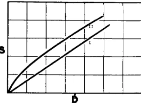
The viscometric approach can be summarized by listing the types of flow curves which can be used in characterizing printing inks. For con- venience, the Newtonian flow curve has been called Type I and is repre- sented by a straight line of slope η through the origin (Fig. 9).
5 8 A. B. Bestul and Η. V. Belcher, Appl. Phys. 24, 696 (1953).
T H E R H E O L O G Y O F P R I N T I N G I N K S 165
I
FIG. 9. Typical flow curves obtained by plotting stress (S) versus rate of shear (D). Key: I, Newtonian—vehicles and thin inks; I I , Pseudoplastic—typical of most inks. Recommended nomenclature for Type I I flow is Shear Thinning.68a
In the flow curves of most printing inks an apparent linear portion is attained at shear rates as low as 50-100 sec.- 1 In the absence of additional information, this curve can be characterized as Type II (Fig. 9) and can be used in determining so-called plastic viscosities and yield values, which are not dealt with extensively in this chapter because they have only empirical value. Artfully, however, the slope U and the intercept So of the flow curve can be used to characterize inks as we have seen. The ratio So/U has been called 'Shortness."
If the slope of this linear portion is less than the viscosity calculated from the Einstein equation, the flow curve cannot possibly maintain linearity; if it were to do so, the viscosity at high shear rates would be less than the ideal value based on the volumetric and shape factors alone.
Consequently, one can predict with assurance that a flow curve cannot be continuously linear if the slope is less than the calculated ideal viscosity.
That the apparent linearity is accidental in some cases and results from the fact that the flow curve approaches an inflection point was demon- strated by Ostwald.59 He was the first to investigate the high shear phe- nomena of anomalous systems and found that the concavity was reversed, just as predicted above, giving rise to a third type of flow curve (Type III, Fig. 10). This reversal was not due to the onset of dilatancy but resulted from the gradual disappearance of the structure responsible for the viscous anomaly. Thus, the Ostwald curve is pseudoplastic at low shear but eventually settles down to an extensive range of Newtonian behavior.
Theoretically, dilatancy or rheopexy can set in at the upper end of the curve, which means that a system can exhibit both pseudoplastic and dilatant behavior. Printing inks may actually behave as Newtonian systems under the conditions found in the distribution phase, but must assume
6 8a R. R. Myers, D. R. Brookfield, F. R. Eirich, J. D. Ferry, and R. N. Traxler, Trans.
Soc. Rheol. 3, in press (1959).
" W. Ostwald, Kolloid-Z. 36, 99 (1925); 47, 176 (1929).
some pseudoplastic character in the post-printing phase either as a result of drainage into the substrate or from physical changes in the film after deposition. Structure buildup may be physical or it may be induced by chemical change as in the oxidation-polymerization of oils.
FIG. 10. Ostwald flow curve produced by anomalous systems, obtained by plotting stress OS) versus rate of shear (D).
R A T E O F S H E A R . D ( S E C r1)
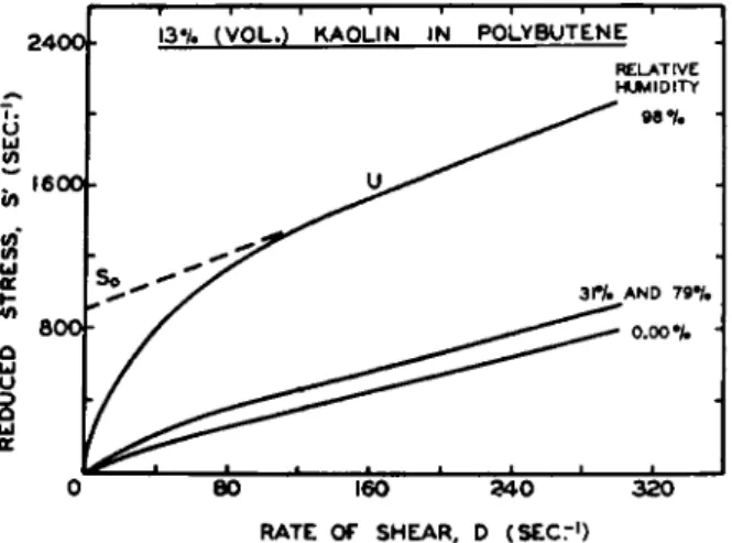
FIG. 11. Flow curves of dispersions made from clays stored at various relative humidities.
Generally, structures of the strength needed to resist excessive penetra- tion of a porous substrate can be observed only at exceedingly low shear stresses. Even then, their contribution to the properties of a film at rest can only be inferred from flow data. For example, dispersions made from clays conditioned at various relative humidities60 produced flow curves in the low shear range that followed the trend shown in Fig. 11. Observe the slight upward displacement of the flow curve when a monolayer of
6 0 R. R. Myers, J. C. Miller, and A. C. Zettlemoyer, J. Appl. Phys. 27, 468 (1956).
2 4 0 0 f - 1 3 % ( V O L . ) K A O L I N I N P O L Y B U T E N Ε RELATIVE HUMIDITY
T H E R H E O L O G Y O F P R I N T I N G I N K S 167
RELATIVE P R E S S U R E , P/ft>
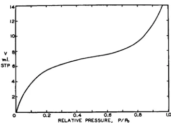
FIG. 12. Water isotherm of a kaolinite clay showing the small water uptake between 0.3 and 0.8 relative humidity.
water was adsorbed on the clay surface before compounding the dispersion.
This displacement is a reflection of a noticeable "shortening" of the system (yield value divided b y plastic viscosity increases) ; but it is nowhere near as drastic a change as when water is allowed to accumulate to multilayer depths on the clay surface.
Comparison of Fig. 11 with the isotherm representing the adsorption of water on clay at 25° C. (Fig. 12) clarifies the points made in the preceding paragraph. Figure 12 gives unmistakable evidence that the uptake of water in the humidity range from 0.30 to 0.80 does not increase significantly;
on the other hand, the 0.30 to 0.80 "plateau" differs from the 0.00 and 0.90 relative humidity points. Drastic changes in water content of the extender are reflected in drastic changes in the low shear flow curves of the resulting dispersion. K r u y t and Van Selms61 have explained this change in con- sistency b y postulating that water bridges connect the individual particles, thereby creating particle-particle contacts through the aqueous film. These contacts become more potent as the depth of the film is increased sufficiently to allow it to provide an excess of water in the capillaries between adjacent particles.
VI. Tack and Related Phenomena 1. T h e N a t u r e o f t h e S p l i t t i n g I n k F i l m
In spite of the advances described in the preceding section, the conclusion has been reached in many quarters that the viscometric approach to the
61 H. R. Kruyt and F . G. van Selms, Ree. trav. chim. 62, 407, 415 (1943).
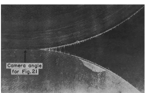
FIG. 13. Filamentation in a roll nip. The side view was taken using a microflash technique by Lars Sjodahl, Interchemical Corporation, Chicago, Illinois.
study of printing inks is destined to be incomplete. The chief reason for this stand is the fact that the shear pattern in a rotational viscometer does not resemble that encountered by the ink at most stages of the printing process. In addition, the behavior of the system undergoing continuous shear is quite different from its behavior during the intermittent shear which occurs in its repeated passage through roller nips.
Whether the split is between rolls, or between roll and plate, or plate and paper, Sjodahl62 has shown that the ink splits in filaments, as evidenced by the side view of a roller system shown in Fig. 13. This finding, coupled with the fact that split takes place exceeding^ rapidly in practice, has given rise to the concept that viscoelasticity is involved. Thus, it would be expected that viscosity alone would sometimes fail to account for ink behavior on a press, although not all printing ink rheologists agree that elasticity is involved. Some believe that tack is related solely to viscosity, in a manner not yet elucidated.
2. F O R C E A N A L Y S I S OF T A C K
Under the conditions in which the tack of printing inks is manifest, the material undergoes a type of flow reminiscent of the elongation of a filament (see Chapter 15). The chief point of departure from this model occurs when
62 L. Sjodahl, Paper presented at the First Annual Meeting of the Technical Association of the Lithographic Industry, Chicago, Illinois. April, 1949; Am. Ink Maker Μ, 31 (1951).
T H E RHEOLOGY OF PRINTING INKS 169 the forces involved in the formation of the filament are considered. It is conceivable that the dynamic requirements for filament formation are larger than those required for its subsequent elongation. Stefan63 has calculated the force F required to separate two plates of radius a from distance hi to final distance A2 :
where t is the time required to effect the separation, h2 is the initial clear- ance hi the final clearance, and a the plate radius. This equation was devel- oped for the elongation of a single filament and appears to be valid for times in excess of one second. However, separation times of this order of magnitude are unrealistic in the case of the split of printing inks in a roller system. Furthermore, the separation of parallel plates in a direction normal to their surfaces does not exactly duplicate the situation existing on a roller system. Consequently, a new equation must be sought.
3. INSTRUMENTATION
The oldest technique for measuring "tack" depends upon the craftsman's middle finger by which he pats out a dab of ink on the paper to printing thickness and then discerns the resistance to the snap of the finger away from the film. In spite of its primitive and subjective nature, the method is still widely and successfully used.
The mechanical tack finger of Green64 was an attempt to attach a number to the craftsman's test. It has been supplemented by the design of Curado,65 in which the alternate compressive and tensile forces impressed on an ink are measured by a piezoelectric crystal. Both of these devices differ from practice in that the split involves motion of the surfaces normal to each other and in that the milling of air into the ink by the rollers is not dupli- cated in the test.
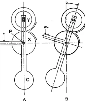
The closest approach which has been made to the measurement of the tack of an ink as found on the press was made by Reed66 who designed an instrument called the Inkometer. This instrument measures the torque exerted upon one roll of a simple distributing system as the ink is being worked. The torque is transmitted through a linkage to a balance arm above the torque roller on which readings are taken as depicted in Fig. 14.
The Inkometer has been used successfully in routine control tests in
6 3 M. J. Stefan, Sitzber. Akad. Wiss. Wien. Math-Naturw. Kl. Abt. II 69, 713 (1874).
64 H. Green, Ind. Eng. Chem., Anal. Ed. 13, 632 (1941).
6 6 Although Curado's data have not been published, they indicate that tensile strengths above 15 p.s.i. are not found in printing inks.
6 6 R. F. Reed, Am. Ink Maker 17, 27 (1939).
(5)
A B
FIG. 14. Diagramatic illustration of the Inkometer principle. A . The instrument rotating without ink at the outset is zeroed by adjusting weight w. B. When the inked rollers X and Y rotate, the additional weight W required to realign the assembly about shaft Ρ is a measure of the torque exerted by the splitting ink film. C is a counterweight.
the manufacture of inks, in correlations with trapping in wet multicolor printing,67 in correlations with the transfer of inks on three-roll mills,68
and in an empirical test for ink stability, particularly in heatset and steamset inks. These inks dry by burning off and water sorption (thus precipitating the resin), respectively.
Limitations of the Inkometer are that it does not exactly dupl'cate a printing press, partly because the optimum ink film thickness for measure- ment is several times greater than that found on presses (7 μ) and partly because equilibrium readings are exceedingly difficult to obtain. Super- imposed upon these drawbacks is the fact that the torque roller is made of a rubber composition, and no composition has been developed which will insure the permanency of the characteristics of such rollers. On one occa- sion the solvent may be absorbed by the rollers, producing a gradual increase in torque; on another, solvent or plasticizer may exude from the rollers and produce a diminution of the Inkometer reading. Distortion of
6 7 A . C . Zettlemoyer, C . T. Dickert, W. C . Walker, and R. R. Myers, see reference
17.
6 8 This finding is covered by National Printing Ink Research Institute Project Report No. 32 on Ink Transfer through the Three-Roll Mill.
THE RHEOLOGY OF PRINTING INKS 171 the composition roller is always present. Some attempts have recently been made to attach the Inkometer directly to the distribution system of presses.69
Other measurements of the forces involved in the splitting of ink films have been provided by Duffie70 and Voet and Geffken71 who measured the decrease in kinetic energy suffered by a rolling cylinder as it passes over an inked surface set on an inclined plane. This work culminated in the concept of tack as an energy density, with energy requirements dependent upon the volume of ink transferred from plate to roller. One of the prob- lems in experimenting with the inclined plane tackmeter arises from the difficulty in obtaining good, reproducible contact between the ink film and surface to be wetted. Sometimes the cylinder is covered with paper to simulate printing, but the pressures achieved are not nearly as great as on printing presses.
Banks and Mill72 sought an answer to the question of how great a tensile force can be supported by an ink film by a method based on impact loading.
Their conclusion, that the pressure in the interior of an ink film cannot fall below zero absolute, has in effect declared that a fundamental difference exists between a printing ink and a solid or pure liquid, for these materials can maintain tensions much higher than the equivalent of one atmosphere.
The importance of tack in industrial processes has led to the adoption of many empirical testing instruments such as the Gardner Touch Con- troller, Gardner Magnetic Tack Test, and Blom Tack Tester.73 One of the simplest and most used empirical techniques for measuring tack is the rolling ball7 4 - 76 test, which consists of timing the descent of a ball over a tacky film on an inclined plane. Its limitations are best described by point- ing out that the descent is influenced by the amount of material pushed ahead of the ball as well as the retardation due to splitting behind the ball. The rolling cylinder77 -7 8 is a variation of this technique.
69 Paira Ann. Rept. 1953.
7 0 E. Duffie, private communication.
7 1 A. Voet and C. F. Geffken, Ind. Eng. Chem. 43, 1614 (1951).
7 2 W. H. Banks and C. C. Mill, J. Colloid Sei. 8, 139 (1953).
7 3 H. A. Gardner and G. G. Sward, "Physical and Chemical Examination of Paints, Varnishes, Lacquers and Colors," 11th ed., pp. 155, 156. Gardner Laboratory, Inc., Bethesda, Maryland, 1950.
7 4 R. H. Gilbert, V. F. Downing, and T. E. Kalber, Paper presented at the Third Annual Meeting of the North Jersey Section Science Groups of the American Chem- ical Society, Newark, New Jersey. January, 1951.
7 6 J. L. Overholt and A. C. Elm, Ind. Eng. Chem. 32, 378 (1940).
7 6 H. Wolff and G. Zeidler, Paint Technol. 1, 387 (1936).
7 7 Β. V. Deryagin, S. M. Sovokin, and A. P. Poretskayeo, "Physico-Chemical Fundamentals of the Printing Process." Graphic Institute, Moscow, 1937.
7 8 A. Voet and C. F. Geffken, see reference 71.
τ
γLOADING TIME, SEC.
FIG. 15. Determination of contact points of a mineral oil from times of rupture and loading. From H. Heidebroek and E. Pietsch, Forschung 12, 74-87 (1941).
One significant experimental condition must be met in the measurement of tack. Scott79 showed that it was mandatory that intimate contact be made between the liquid and solid surfaces. Heidebroek and Pietsch80 arrived at the same conclusion in a study of the forces required to pull one block from another connected with a simple liquid, and found that a limit- ing impulse (Ft) for separation was reached only after a given weight had had been applied for a definite time. Figure 15 shows that the rupture time reached a maximum only after complete contact was achieved.
Bikerman81 has concluded that only viscous forces are involved in the peeling of a flexible substrate from a plane surface in contact with a New- tonian liquid. Apparently viscometry, if conducted properly, would provide the material constants needed to characterize the low shear flow behavior of a system under tension, but additional knowledge of the flow pattern (i.e., the kinematics) is needed before a complete description can be given of tack on roll systems.
4. COHESIVE STRENGTH OF LIQUIDS AND DISPERSIONS
Various methods of estimating the theoretical strength of liquids under tension have been used,8 2 , 83 many of which give very high values (20,000
7 9 J. R. Scott, Paint Technol. 10, 218 (1944).
8 0 E. Heidebroek and E. Pietsch, Forsch. Gebiete Ingenieurw. 12, 74 (1941).
8 1 J. J. Bikerman, Trans. Soc. Rheol., 2 , (1958).
8 2 S. W. Benson and E. J. Gerjouy, J. Chem. Phys. 17, 914 (Oct. 1949).
8 3 S. Glasstone, "Textbook of Physical Chemistry/' 2nd ed., p. 479. Van Nostrand, New York, 1946.
THE RHEOLOGY OF PRINTING INKS 173 atmos. for water). Recent theoretical developments8 4-85 give tensile strengths an order of magnitude lower.
Experimental measurements of the stress that a liquid will withstand before cavitation have been made with a number of different techniques.8 6 - 92 None of the measurements have given values over 300 atmos. tension, and those stresses were obtained under stringently sterile conditions. Experi- mental verification of the theoretical tensions has not yet been achieved because of foreign particles, small gas bubbles, the surface of the container, etc. An impure liquid should cavitate at the interface of foreign nuclei at much lower tensions than the values obtained under carefully controlled conditions. Theoretically, the tensile strength of a liquid is expressed as93
Ρ = Τ (α/β) - PA . (6)
For most liquids β, the coefficient of compressibility, is of the order of magnitude of 10_ 4/atmos. and a, the coefficient of thermal expansion, is about 10~3/deg. Consequently, the value of Ρ derived theoretically is thousands of atmospheres. And yet, these values are not obtained experi- mentally. The reason is attributed to the presence of nuclei which serve to form cavities long before the theoretical tension has been reached.
The splitting of an ink film is therefore believed to represent a combina- tion of viscous flow in the time allotted and of fracture resulting from the stress exceeding the elastic limit of the ink. The number of nuclei and their interfacial attraction apparently determine the forces involved in the process.
In the case of rapid separation of two parallel plates, the liquid yields by laminar shear only insofar as its cohesive strength will permit. If the separation rate is sufficiently high to develop internal stresses that exceed the cohesive strength, the liquid will fracture as a brittle solid. This type of behavior has long been construed as elastic, but in the final analysis it does not even depend on the molecular properties of the material. Viscosity is involved because the product of viscosity and separation rate determines the internal stress, as will be shown later.
84 L. Bernath, Ind. Eng. Chem. 44, 1310 (1952).
8 6 Η. Ν. V. Temperley, Proc. Phys. Soc. (London) A 5 8 , 436 (1946).
8 6 L. J. Briggs, J. Appl. Phys. 19, 1062 (1948).
8 7 R. Budgett, Proc. Roy. Soc. A86, 25 (1912).
8 8 R. B. Dean, J. Appl. Phys. 18, 446 (1944).
8 9 H. H. Dixon, Proc. Roy. Dublin Soc. [N.S.] 14, 229 (1914).
9 0 W. B. Kenrick, C. S. Gilbert, and K. L. Wismer, J. Phys. Chem. 28, 1297 (1924).
91 Η. Ν. V. Temperley and R. Chambers, Proc. Phys. Soc. (London) A58, 420 (1946).
9 2 R. S. Vincent, Proc. Phys. Soc. (London) A 5 5 , 41 (1943).
9 3 S. Glasstone, see reference 83, p. 480.