Pseudo-ductility and reduced notch sensitivity in multi-directional all-carbon/epoxy thin-ply hybrid composites
Gergely Czél
a,b,⇑, Tamas Rev
b, Meisam Jalalvand
b,c, Mohamad Fotouhi
b,d, Marco L. Longana
b, Oliver J. Nixon-Pearson
b, Michael R. Wisnom
baDepartment of Polymer Engineering, Faculty of Mechanical Engineering, Budapest University of Technology and Economics, M}uegyetem rkp. 3., H-1111 Budapest, Hungary
bBristol Composites Institute (ACCIS), University of Bristol, Queen’s Building, BS8 1TR Bristol, United Kingdom
cDepartment of Mechanical and Aerospace Engineering, University of Strathclyde, 75 Montrose Street, Glasgow G1 1XJ, United Kingdom
dDepartment of Design and Mathematics, University of the West of England, Bristol BS16 1QY, United Kingdom
a r t i c l e i n f o
Article history:
Received 28 March 2017
Received in revised form 21 September 2017
Accepted 25 October 2017
Keywords:
B. Fragmentation B. Delamination C. Damage mechanics D. Mechanical testing
a b s t r a c t
Un-notched and notched tensile response and damage accumulation of quasi-isotropic carbon/epoxy hybrid laminates made of ultra-high modulus and intermediate modulus carbon fibre/epoxy thin-ply prepregs were studied. It was confirmed that the ply fragmentation demonstrated previously in unidirec- tional hybrids as a successful pseudo-ductility mechanism can be transferred to multi-directional lami- nates. Furthermore, reduced notch sensitivity was demonstrated in quasi-isotropic specimens for both open holes and sharp notches as a result of local ply fragmentation around the notch.
Ó2017 The Author(s). Published by Elsevier Ltd. This is an open access article under the CC BY license (http://creativecommons.org/licenses/by/4.0/).
1. Introduction
High performance composites reinforced with carbon and glass fibres exhibit high specific strength and stiffness, which makes them desirable for lightweight applications including spacecraft, aero-structures, motorsports and recreational equipment. In line with the commonly observed trade-off between strength and duc- tility[1–5]in metals and other structural materials, stiff and strong composites generally fail suddenly without sufficient warning and residual load bearing capacity. The catastrophic failure of compos- ites is usually compensated for by cautious design and high safety- factors which leads to significant overdesign hindering the full exploitation of their mechanical properties. High performance pseudo-ductile composites exhibiting a safe, progressive failure process similar to yielding and strain hardening of metals accom- panied by detectable damage which can serve as a warning sign well before final failure are therefore of high interest.
The ideal approach to provide fibre reinforced composites with ductility would be to replace their intrinsically brittle constituents
(carbon, glass etc. fibres, thermoset polymer matrix) by more duc- tile ones. There are two different directions of new material devel- opment: There is significant interest in finding tougher and more crack-resistant resins (mainly thermoplastic polymers) which can improve matrix-dominated properties such as delamination resis- tance. However the brittle failure of unidirectional (UD) compos- ites needs to be addressed by focussing on fibre development as the tensile stress-strain response of high performance composites is usually fibre-dominated. Although there are some promising ductile fibres developed recently such as nanotube[6], regenerated cellulose[7]and other polymeric fibres, their typical elastic mod- ulus and strength are significantly lower than those of conven- tional carbon fibres. It is also noted that the development to make a new fibre suitable for structural applications is extremely challenging and the verification and commercialisation is a long process. Excellent ductility was reported recently by Allaer et al.
and Callens et al. using low diameter stainless steel fibres com- bined with various matrix materials[8–11]. However the relatively high density of the obtained composites may limit their applica- tion in lightweight structures.
Another approach to generate additional strain in laminated composites is the design and modification of the architecture of materials made of commercially available constituents. A few mechanisms were identified and investigated within the High
https://doi.org/10.1016/j.compositesa.2017.10.028 1359-835X/Ó2017 The Author(s). Published by Elsevier Ltd.
This is an open access article under the CC BY license (http://creativecommons.org/licenses/by/4.0/).
⇑ Corresponding author at: Department of Polymer Engineering, Faculty of Mechanical Engineering, Budapest University of Technology and Economics, M}uegyetem rkp. 3., H-1111 Budapest, Hungary.
E-mail address:czel@pt.bme.hu(G. Czél).
Contents lists available atScienceDirect
Composites: Part A
j o u r n a l h o m e p a g e : w w w . e l s e v i e r . c o m / l oc a t e / c o m p o s i t e s a
Performance Ductile Composite Technologies (HiPerDuCT) pro- gramme such as: additional strain from realignment of off-axis fibres and shearing of the matrix[12]. Interface modification on the fibre[13–15]and on the ply level[16]as well as designed dis- continuities [17,18] were also found to be suitable for delaying fracture and generating stress-strain non-linearity through con- trolled damage before final failure.
Hybridisation of fibre types at different levels (laminate, ply, tow) is a mature approach for increasing the elastic modulus of the high strain component and introducing a gradual failure pro- cess with final failure close to the failure strain of the high strain fibres. However hybrids usually show an unfavourable major load drop at the failure of the low strain constituent if the level of dis- persion is too low and/or the volume fraction of the low strain fibres is too high. A few reviews[19–23,3]summarise the exten- sive literature on hybrid composites accumulated since the early 1970s. Based on the literature, the most successful approach is the interlayer or layer-by-layer hybridisation partly for its simplic- ity, as intimate mixing (or intermingling) of different continuous fibres providing high dispersion is currently only feasible on a small scale. If an interlayer hybrid is made of very thin plies of a single layer of fibres, modelling has shown that the dispersion can be even higher than that for random packing [24]resulting in a favourable stable failure process. Aligned short fibre hybrid composites [25] however demonstrated excellent dispersion of the constituent fibres, stiffness close to that of continuous fibre composites and pseudo ductility with highly non-linear stress- strain curves. The so-called hybrid effect commonly reported for glass/carbon fibre reinforced hybrids as a significant improvement in the carbon component failure strain was investigated in[26]and the importance of the correct carbon composite baseline strain achievable with delaminating UD hybrid specimens [27] was highlighted.
The authors of this paper have demonstrated pseudo-ductility in both glass-carbon/epoxy[28] and all-carbon/epoxy [29] thin- ply UD interlayer hybrid composites in tension earlier with high initial modulus, pseudo-yielding, a flat (or rising) stress plateau and further increase in load towards final failure. Fragmentation of the low strain layer and stable delamination were identified as the key damage mechanisms and implemented in the dedicated numerical [30] and analytical [31] modelling and design tools developed for the UD hybrids. The reported pseudo-ductility was achieved by hybridising some of the recently introduced thin-ply carbon prepregs, which are studied extensively for their unique properties [32–39]. These include their low thickness enabling highly dispersed lay-up designs, significantly decreasing the mini- mum thickness of multi-directional e.g. quasi-isotropic (QI) plates and favourable intrinsic damage suppression properties due to the low energy released upon fracture of thin plies. The general conclu- sion of the studies is that early damage in thin-ply QI laminates (transverse matrix cracking, splitting, free-edge delamination) is suppressed, therefore the strength may be increased but the failure of non-hybrid thin-ply plates becomes more brittle than that of standard ply-thickness laminates.
The aim of the present study is to demonstrate pseudo-ductility in multi-directional hybrid laminates which have a lot higher merit in structural applications than unidirectional ones. To this end, the benefits of UD hybrid composites (i.e. fragmentation of the low strain component) is combined with the favourable general damage suppression due to having thin plies in a laminate. Our composite architecture design approach is based on thin-ply all-carbon (intermediate modulus- IM/ultra-high modulus- UHM carbon) UD hybrid sublaminates as building blocks stacked together into symmetric quasi-isotropic plates. The expected tensile response features the suppression of unwanted damage (transverse cracking, delamination) and exploitation of controlled
fragmentation within the 0° sublaminates starting at a known strain (i.e. the failure strain of the low strain carbon plies). Some of the initial results were presented recently in a conference by the authors[40], but this more complete study includes one more material configuration and a comprehensive damage analysis.
Amacher et al.[41]also presented their work on quasi-isotropic thin-ply all-carbon/epoxy hybrids with a different design concept and architecture at the same conference and indicated the scope for pseudo-ductility.
The damage development in the QI hybrid plates was moni- tored with various state of the art techniques. Delaminations and fibre fractures in the tested specimens are detected and analysed by X-ray computed tomography (X-ray CT) after tests interrupted at pre-defined typical damage states. The damage was segmented by defining certain grey-scale thresholds using the software AvizoÒ 7.0 in the same manner as in Refs.[42,43]. Stress concentrations around two different notch types (open hole and sharp notch) were investigated by digital image correlation (DIC). Acoustic emission events originating primarily from fibre fractures were recorded on-line during selected tests to monitor the damage accumulation in the hybrid laminates.
2. Material and configuration design
This section gives details of the hybrid sublaminate concept, the applied materials and the design considerations to assure stable pseudo-ductile failure of the multi-directional hybrid laminates.
2.1. Concept
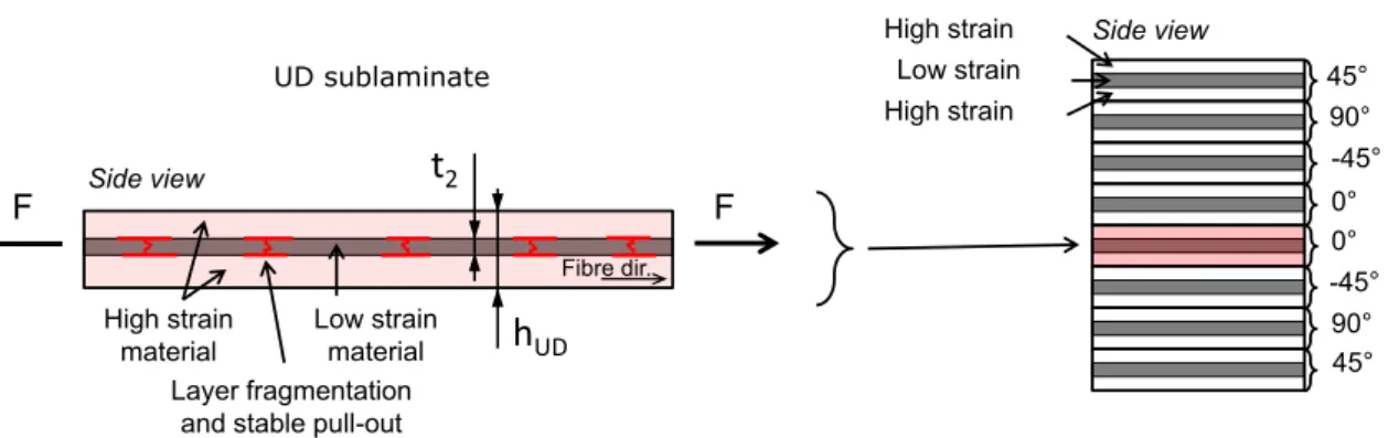
The basic concept of this study is to use thin UD pseudo-ductile interlayer hybrid laminates comprising low strain and high strain materials (LSM and HSM respectively) as building blocks for multi-directional plates as highlighted inFig. 1. The ultimate goal is to transfer the safe and progressive failure process of the UD sub- laminates to a multi-directional laminate and provide pseudo- ductile tensile response in all loading directions. To this end, the beneficial pseudo-ductile failure mechanisms i.e. LSMfragmenta- tion (stable, multiple layer fractures) and stable pull-out (stable intra-sublaminate delamination) are promoted and exploited in the multi-directional hybrid plates, but other less stable damage mechanisms i.e. splitting and unstable inter-sublaminate (free- edge) delamination are suppressed until a given, higher strain.
The most important damage mechanism putting pseudo-ductile failure at risk is unstable delamination, which can happen at two different levels in the designed laminates as explained inFig. 2.
(i)Intra-sublaminate delaminationcould take place within the sub- laminate if the LSM releases more energy at its first fracture than the mode II fracture toughness of the interface. (ii) Inter- sublaminate delaminationcould occur due to the free-edge stresses at the interface between neighbouring hybrid-sublaminates caused by their different orientations. This is a mixed mode delam- ination and therefore its prediction and control is more challenging than those of the other pure mode II intra-sublaminate one anal- ysed in our previous works on UD hybrids [28,30]. The inter- sublaminate delamination would take place at the specific inter- faces (symmetrically to the mid-plane in symmetric laminates) where the energy release rate is the highest in relation to the frac- ture energy within the laminate.
2.2. Materials
The materials considered for design, and used for the experi- ments were thin carbon/epoxy prepregs from North Thin Ply Tech- nology and SK Chemicals made of different type intermediate
modulus (IM), and ultra-high modulus (UHM) carbon fibres. The epoxy resin systems in the prepregs were ThinPreg 120 EPHTg- 402 (North TPT) and K50 (SK chemicals), both having 120°C cure temperature. The resins were found to be compatible, although no details were provided by the suppliers on their chemical formu- lations. Good integrity of the hybrid laminates was confirmed dur- ing test procedures and no phase separation was observed on cross
sectional micrographs. Basic properties of the applied fibres and prepreg systems can be found inTables 1 and 2. Please note, that the fibre volume fractions (Vf) of the applied thin prepregs were less than 50%, significantly lower than the typical 60% for high per- formance composites, which limited the maximum achievable stiffness and strength of the developed pseudo-ductile configurations.
Fig. 1.Schematic showing the sublaminate concept for multi-directional composite plates. (For interpretation of the references to colour in this figure legend, the reader is referred to the web version of this article.)
Fig. 2.Two levels of delamination in multi-directional hybrid laminates indicated by red lines. (For interpretation of the references to colour in this figure legend, the reader is referred to the web version of this article.)
Table 1
Fibre properties of the applied UD prepregs based on manufacturer’s data (Numbers in brackets indicate the tow count in 1000 filaments. IM- stands for intermediate modulus, UHM- ultra-high modulus).
Carbon fibre type Manufacturer Elastic modulus
[GPa]
Strain to failure [%]
Tensile strength [GPa]
Density [g/cm3]
Torayca T1000GB (12k) Toray 294 (IM) 2.2 6.37 1.80
Pyrofil MR60H 24P (12k) Mitsubishi Rayon 290 (IM) 1.9 5.68 1.81
Granoc XN-80 (12k) Nippon GFC 780 (UHM) 0.5 3.43 2.17
Table 2
Cured ply properties of the applied UD prepregs.
Prepreg material Manufacturer Nominal fibre areal densitya [g/m2]
Fibre volume fractiona Vf[%]
Cured ply thicknessb [mm]
Initial modulusb [GPa]
T1000/epoxy North TPT 28 48.1 32.3 142.9
MR60/epoxy SK Chemicals 22 47.8 25.4 140.4
XN-80/epoxy North TPT 63 46.5 62.5 364.4
a Based on manufacturer’s data.
b Calculated using manufacturer’s data.
2.3. Design of hybrid laminates
The hybrid laminates were designed according to the following considerations: (i) the hybrid sublaminate building blocks should fail progressively byfragmentationandstable pull-outof the LSM (unstable intra-sublaminate delamination has to be suppressed), (ii) the thickness of the sublaminate should be kept low in order to hinder inter-sublaminate (free-edge) delamination, (iii) double 90°layers in the middle of the laminate should be avoided to sup- press transverse cracking and induced delamination.
Considering the above points the following lay-up sequence was proposed (each orientation represents a three-layer UD hybrid sublaminate): [45/90/45/0]s.
Eq.(1)presented earlier in[28]was adopted here as a criterion to avoid intra-sublaminate delamination by keeping the mode II energy release rateGIIat first LSM fracture lower than the fracture toughnessGIICof the applied materials.
GIIC>GII¼
e
22bE2t2ð2E1t1þE2t2Þ 8E1t1ð1Þ
whereE1is the initial modulus of the HSM,E2is the initial modulus of the LSM,t1= (hUD-t2)/2 is the thickness of one HSM layer,t2is the thickness of the LSM layer as shown inFig. 1,
e
2bis the breaking strain of the LSM.Table 3summarises the sublaminate structure, materials, and some other parameters including the energy release rate (G) values at first LSM fracture for the two different QI plate configurations.
For both sublaminate configurations the intra-sublaminate mode II energy release rates are lower than the measured critical energy release rate,GIIC=0.65 N/mm and 1.05 N/mm of the T1000/XN-80 and MR60/XN-80 configurations respectively (seeTable A1), there- fore intra-sublaminate fragmentation and stable local delamina- tion is expected before inter-sublaminate (free-edge) delamination initiation for both configurations. The reason for the different fracture toughness values is that the constituent pre- pregs of the hybrids had two different matrix materials (SK chem- icals K50 for MR60 carbon/epoxy and North ThinPreg 120 EPHTg- 402 for T1000 and XN-80/epoxy). A short summary of the fracture toughness measurements can be found in theAppendix.
The second criterion for inter-sublaminate delamination was harder to assess, because of the unknown mixed mode ratio around the free-edge. The maximum inter-sublaminate energy release rates of each configuration for delamination between the hybrid sublaminates with different fibre orientation were calcu-
lated at the failure strain of the low strain material of the hybrid sublaminate using the O’Brien method [44] and are shown in Table 3. This is an analytical method based on the stiffness reduc- tion due to delamination symmetric to the mid-plane. The energy release rate was initially calculated for all interfaces between the differently oriented UD sublaminates and the maximum value was found at the interface between the 90°and 45°layers for both material combinations as shown inFig. 2. The method calcu- lates the total energy release rate so it should be compared against mixed-mode critical energy release rates. The calculated G values at LSM failure included inTable 3are lower than either the typical mode I or II fracture toughness of composite interfaces therefore inter-sublaminate (free-edge) delamination is not expected in either of the designed QI hybrid laminates at least before the start of LSM fragmentation.
The third criterion was satisfied by applying the [45/90/45/0]s
lay-up sequence. The blocked 0°sublaminates were put in the mid- dle to avoid early delamination which could have started from the matrix cracking of blocked 90°sublaminates.
The configurations designed based on the properties of the available prepreg materials and the above criteria are summarised inTable 3.
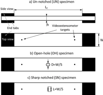
Two different notches were machined in the QI hybrid speci- mens: (i) open hole with a 3.2 mm nominal diameter and (ii) 3.2 mm nominal width sharp notch. Un-notched tensile tests of the UD sublaminate were also executed in order to have an under- standing of how the pseudo-ductility of the hybrid sublaminates compares with that of the laminates.Table 4shows the specimen types and number of tested specimens.
3. Experimental 3.1. Specimen geometry
The specimens tested within the study were parallel edge end- tabbed tensile specimens. Nominal specimen dimensions were overall length: 240 mm, free length:Lf= 160 mm, width:W= 20 mm, variable thickness: h for the UD sublaminates and overall length: 120 mm, free length:Lf= 64 mm, width:W= 16 mm and variable thickness:hfor the QI un-notched, open-hole and sharp notched specimens. The characteristic size of the notch was chosen to be one fifth of the specimen width.Fig. 3shows the geometric parameters on the side and top view schematics of a tensile spec- imen as well as the notch geometries.
Table 4
Types and number of tested tensile specimens (type abbreviations are shown in brackets).
Sublaminate type UD sublaminate QI un-notched QI open-hole QI sharp-notched
(UD) (QI-UN) (QI-OH) (QI-SN)
T1000/XN-80 6 6 6 6
MR60/XN-80 6 6 6 6
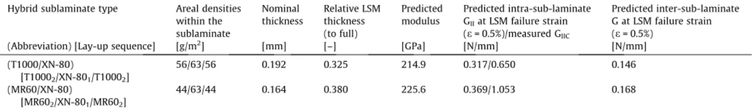
Table 3
Properties of the quasi-isotropic laminate configurations designed and tested within the present study. Both plates were made with [45/90/45/0]slay-up sequence, where each angle in degrees represent the orientation of a whole three-layer hybrid sublaminate.
Hybrid sublaminate type Areal densities within the sublaminate
Nominal thickness
Relative LSM thickness (to full)
Predicted modulus
Predicted intra-sub-laminate GIIat LSM failure strain (e= 0.5%)/measured GIIC
Predicted inter-sub-laminate G at LSM failure strain (e= 0.5%)
(Abbreviation) [Lay-up sequence] [g/m2] [mm] [–] [GPa] [N/mm] [N/mm]
(T1000/XN-80)
[T10002/XN-801/T10002]
56/63/56 0.192 0.325 214.9 0.317/0.650 0.146
(MR60/XN-80)
[MR602/XN-801/MR602]
44/63/44 0.164 0.380 225.6 0.369/1.053 0.168
3.2. Specimen manufacturing
UD three layer hybrid sublaminates of either T1000/epoxy or M60/epoxy as the HSM and XN-80/epoxy as the LSM respectively (seeFig. 1) were prepared first with the stacking sequences given inTable 3. using individual plies cut out from the prepreg rolls according to the designed orientation of the given sublaminate in the QI plate. These prepared building blocks were then stacked together by aligning the straight edges of the sublaminates and keeping the pre-defined orientations to build the QI hybrid lami- nates. All applied prepregs had similar 120°C cure epoxy resin sys- tems and were cured in an autoclave according to the manufacturer’s recommendation: 2 h at 120°C temperature and 0.7 MPa pressure. The individual specimens were cut from 300 300 mm plates with a diamond cutting wheel. Finally 40 mm long tabs of glass fabric/epoxy were bonded to the ends of the speci- mens with a two component epoxy adhesive. The two different type 3.2 mm nominal size notches were manufactured as fol- lows:(i) open hole fabricated with a diamond drill on a CNC milling machine and (ii) sharp notch fabricated in two steps: (1) milling of a 2 mm long slot with a 1 mm diameter ball end mill and (2) man- ual cutting of the rest of the nominal notch width symmetrically with a 180mm wide diamond wire saw.
3.3. Mechanical test procedure
Testing of the parallel edge specimens was executed under uni- axial tensile loading and displacement control at a crosshead speed of 1 and 0.5 mm/min for un-notched and notched specimens respectively on a computer controlled Instron 8801 type 100 kN rated universal hydraulic test machine with a regularly calibrated 25 kN load cell and wedge type hydraulic grips. The grip pressure was kept at the minimum required to avoid slippage of the speci- mens in the grips during loading to minimise the through thick- ness compressive stress at the edge of the end-tabs. The relative extensions were measured using an Imetrum video extensometer system with a large nominal gauge length about 10 mm shorter than the free length of the specimens (seeFig. 3). The measured global relative extensions therefore include the intact and the notched parts of the specimens where relevant. The obtained
relative extensions correspond to the surface of the specimens and their accuracy is affected by local and/or global delamination and/or splitting of the plies after the first occurrence of any of these damage events. The measured global relative extensions will be referred to as strains in the text for simplicity. Overall videos recorded by the video extensometer camera were also kept to be used for failure type and sequence characterisation. Digital image correlation (DIC) was applied to capture the local variation of the strain field around the notches. Table 5summarises the applied DIC parameters and the resulting resolutions.
3.4. Results and discussion
This section covers the details of the mechanical testing, and the damage analysis which was performed to investigate the mecha- nisms which were active during the tests of different specimen configurations.
3.4.1. Tensile response of the uni-directional and un-notched quasi- isotropic laminates
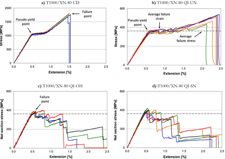
Fig. 4a shows the favourable pseudo-ductile tensile response of the un-notched T1000/XN-80 UD type hybrid sublaminate which agreed well with that expected according to the design considera- tions. The high stiffness, low strain XN-80 fibre reinforced ply started to fragment at around 0.5% strain which will be referred to as the pseudo-yield point determined at the intersection of lines fitted to the initial linear and the plateau parts of the individual stress-strain curves. The pseudo-yield point is the beginning of a stable, progressive damage process along the stress plateau over a range of approximately 0.4% strain when fragmentation and stable local delamination around the cracks in the XN-80 layer took place. After the high (over 1000 MPa) plateau, the stress started to rise again as the T1000 plies started to take more load upon satu- ration of fragmentation. The significant (up to 1%) strain margin between damage initiation and final failure shows the potential to achieve pseudo-ductility in a QI laminate as well if delamination of the off-axis sublaminates is suppressed.
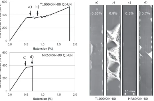
Fig. 4b shows the tensile response of T1000/XN-80 QI-UN type quasi-isotropic un-notched specimens. It can be seen that the pseudo-yield point was at 0.55% strain, about 0.3% lower than the strain at which the first significant (larger than 5%) stress- drops corresponding to inter-sublaminate delaminations occur.
This type of damage was visible from the sides of the specimens during the tests. The stable plateau before the first load drops shows that the pseudo-ductility mechanisms of thin-ply UD hybrids can be successfully exploited in QI laminates as well as in UD ones, and the unstable inter-sublaminate delamination was suppressed until about 0.89% strain on average (see arrow in Fig. 4b and failure strain inTable 6). The failure stress (and strain) of the un-notched laminates was defined at the first significant stress-drop (see arrow inFig. 4b) rather than the maximum stress (i.e. 497 MPa on average for the T1000/XN-80-QI-UN specimens).
X-ray CT scans of Fig. 6 clearly show the large extent of delamination after the first stress-drop along the stress plateau Fig. 3.Specimen schematics: (a) Un-notched, (b) Open-hole and (c) Sharp notched
specimen respectively.
Table 5
Summary of DIC equipment, parameters and resulting resolutions.
Software DaVis 8.2.1
Subset Size [pixel] 3131
Step Size [pixel] 5
Camera Imager X-lite 16 Mpixel
Lens Tokina AT-X M100 ProD
Image size [pixel] 50773334
Image size [mm] 109.571.9
Spatial resolution [mm] 0.101
Displacement Resolution [lm] 0.3
Strain Resolution [ls] 393
in a T1000/XN-80 QI-UN specimen. This conservative failure point definition is essential not to over-claim the performance of our pseudo-ductile materials as the loss of compressive or bending stiffness makes it unacceptable to have extensive delamination in a structural material. Please note that this failure point is used as a baseline for the assessment of notch sensitivity throughout the paper. The observed damage mechanisms as well as the type and extent of the associated damage are analysed further in Sections 3.4.4–3.4.6.
Fig. 5a shows the tensile response of the MR60/XN-80 UD sub- laminates revealing brittle failure at 0.42% average strain which was unexpected given that there is more than 1% margin between the failure strains of the HSM and the LSM fibres.
In the similar T1000/XN-80 UD hybrid sublaminate pseudo- yielding took place, with fragmentation dominated pseudo- ductile failure. This change in failure mode for the same XN-80 plies cannot be explained by the different thermal residual strains as the materials used in the sublaminates and the thicknesses were Fig. 4.Tensile response of different specimen types made of T1000/XN-80 sublaminates (Dashed lines indicate the failure stress of the QI-UN specimens). (For interpretation of the references to colour in this figure legend, the reader is referred to the web version of this article.)
Table 6
Summary of mechanical test results (Strain refers to global relative extension and it is not corrected with thermal residual strains. CV- Coefficient of variation, UD- uni-directional sublaminate, QI- quasi-isotropic, OH- open-hole, SN- sharp-notched).
Spec. type Nominal thickness/
width/free length
Notch size Measured modulus from nominal thickness
Pseudo-yield strain (first knee point)a
Pseudo- yield/plateau stressa
Failure strain Failure stress (net section for notched) [mm] [mm] (CV%) [GPa] (CV%) [abs.%] (CV rel.%) [MPa] (CV%) [abs.%] (CV rel.%) [MPa] (CV%)
T1000/XN-80 UD 0.192/20/160 – 207.9 (3.0) 0.486 (1.8) 1030.3 (3.9) 1.53b 1680b
T1000/XN-80 QI- UN 1.54/16/64 – 62.2 (2.4) 0.553 (2.8) 344.4 (4.2) 0.895c(9.4) 361.6c(4.9)
T1000/XN-80 QI- OH 1.54/16/64 3.2 – – – 0.568c(3.9) 382.9c(2.4)
T1000/XN-80 QI- SN 1.54/16/64 3.47 (7.6) – – – 0.534c(5.8) 399.5c(4.1)
MR60/XN-80 UD 0.164/20/160 – 217.8 (4.3) – – 0.419d(7.8) 916.3d(7.9)
MR60/XN-80 QI- UN 1.31/16/64 – 73.3 (3.7) 0.533 (2.7) 381.5 (3.2) 0.862c(2.6) 401. 3c(4.7)
MR60/XN-80 QI- OH 1.31/16/64 3.2 – – – 0.463d(4.0) 379.9d(2.0)
MR60/XN-80 QI- SN 1.31/16/64 3.54 (6.2) – – – 0.465d(3.1) 399.9d(4.6)
aRecorded at the intersection of lines fitted to the first quasi-linear and the plateau parts of the stress-strain curves.
b Approximate maximum determined graphically from the aggregated series graphs.
c Recorded at the first major (larger than 5%) stress-drop.
d Recorded at final catastrophic failure.
similar. A possible reason for the change from stable to unstable failure is that the relative LSM thickness was more than 10% higher in the MR60/XN-80 configuration than in the T1000/XN-80 one (seeTable 3), and the ultimate strain of the MR60 fibres was lower than that of the T1000 fibres (1.9 and 2.2% respectively). These con- ditions decreased the safety margin for premature failure of the whole UD hybrid specimens, but this configuration should still have behaved similarly to the previous one. An additional effect could be due to the higher mode II toughness of the MR60/XN-80 hybrid interface than that of the T1000/XN-80 one. A tougher interface suppressing interfacial damage between the LSM and the HSM layer could result in higher stress concentrations in the intact HSM around LSM fractures. Please note that even though low mode II energy release rate is required to avoid unstable delamination of the LSM and HSM layers at first LSM fracture (see Eq.(1)), if it is too low and/or the fracture toughness is too high (i.e. there is a too large margin between them) it may also lead to premature failure of the HSM because of the reduced relief of the stress concentration from the broken LSM in the vicinity of the crack tip in the HSM due to the lack of local interfacial damage.
A similar phenomenon was shown earlier in [30] where scaled laminates with lower LSM thickness failed significantly earlier than those with thicker LSM. FE analysis showed that the interlaminar damage process zone was shorter in the thinner specimens due to the large margin between the low energy release rate and the high interlaminar fracture toughness, so the stress concentration factor was high and as a result, the HSM failed prematurely.
The collected parts of the UD MR60/XN-80 specimens which failed catastrophically around the grips, showed very sharp cracks
through the whole specimen thickness with no signs of significant interfacial damage. High local stress in the HSM around LSM cracks could lead to premature failure of the whole UD specimen by through thickness propagation of one of the first few LSM cracks especially if a crack took place close enough to the end-tabs where additional stress concentrations are present due to load transfer from the grips through shear. On the contrary in the UD T1000/
XN-80 specimens, a number of cracks could form stably in the LSM to establish the stress plateau due to higher HSM strength and enough interfacial damage (longer damage process zone) to decrease stress concentrations around LSM cracks.
Despite the brittle UD sublaminate failure,Fig. 5b. shows an
‘‘elastic-plastic” type response for the MR60/XN-80 QI-UN type (un-notched laminate) specimens. This behaviour looks surprising at first, but more stable response would be expected due to the additional load carrying capacity of the extra plies as well as the shielding effect of the thick blocks of off-axis sublaminates reduc- ing stress-concentrations in the HSM of the 0°sublaminate at the end-tabs. The difference between the UD and QI behaviour of the MR60/XN-80 specimen types is discussed in detail in the next section.
3.4.2. Differences between uni-directional and quasi-isotropic un- notched fragmentation strain
The pseudo-yield strain of the T1000/XN-80 specimens defined as the knee point at the start of the stress plateau (seeTable 6) was shifted from 0.486% for the UD to 0.553% for the QI architecture.
Two potential causes were identified and analysed further: the Fig. 5.Tensile response of different specimen types made of MR60/XN-80 sublaminates (Dashed lines indicate the failure stress of the QI-UN specimens). (For interpretation of the references to colour in this figure legend, the reader is referred to the web version of this article.)
thermal residual strains and changes in the evolution of fragmentation.
The first considered effect is the different thermal residual strains in the two different specimen types (i.e. UD and QI). To further investigate the possible change in failure strain due to different thermal strains, the following coefficients of thermal expansion (CTE) were used: T1000/epoxy: 0.109106 [1/K], XN-80/epoxy: 1.23106 [1/K] in the fibre direction and an estimated 4510-6 [1/K] was used for both materials in the transverse direction based on typical manufacturer’s data and values in the literature. A 100°C temperature drop was consid- ered between the cure temperature (120°C) and room tempera- ture. The residual elastic strain in the XN-80 ply in the centre of the UD sublaminate is calculated to be0.006% (compression), so the corrected pseudo-yield strain of the XN-80 plies in the T1000/XN-80 UD specimens is 0.480%. The thermal residual strain in the 0° XN-80 plies in the QI laminates was analysed based on the classical laminated plate theory (CLT). The fibre direction residual elastic strain was calculated to be 0.0219%
(compression), which indicates that the pseudo-yield strain of the XN-80 plies in the T1000/XN-80 QI-UN laminate is 0.531%.
Although the strain difference between the UD and QI went down from 0.067% to 0.051% it is still significant, so cannot be explained solely by residual stresses.
The second effect is related to the extra layers in the QI plate that may be able to alter the fragmentation process. The stiffness of the surrounding layers can change the stress distribution around a sub-critical cluster of broken fibres in the low strain material: the higher the stiffness of the adjacent layers around the fragmenting layer, the lower the stress in the neighbouring material around the cluster. The stiffness is calculated by multiplication of the load direction modulus and the laminate thickness, (E1h). A laminate analysis indicated that the relative stiffness of the non- fragmenting 0° HSM (T1000) plies to the fragmenting 0° LSM (XN-80) plies is Snon-frag./Sfrag.= 0.82 in the UD hybrid. Repeating the same calculation for the QI hybrid indicates that the ratio is increased to Snon-frag./Sfrag.= 1.94 by the addition of the non- fragmenting off-axis sublaminates. This means that the relative stiffness of the fragmenting plies (0°LSM) compared to the full laminate stiffness in the UD plate is significantly higher than that in the QI plate (Sfarg./Stotal= 0.55 and 0.34 respectively). As a result, the stress concentrations around the sub-critical LSM fibre clusters in the QI laminate are expected to be lower than those in the UD laminate and therefore the clusters should develop at a slower rate, causing a delay in establishing fragmentation. This hypothesis is confirmed by the acoustic emission results ofFig. 11which show that fragmentation started at a significantly higher strain in the QI specimens than in the UD ones.
In the case of the MR60/XN-80 specimens the tensile behaviour was completely different for the UD sublaminates and for the un- notched QI specimens (i.e. catastrophic and pseudo-ductile respec- tively). Effectively the non-fragmenting part of the laminate (which was only the 0°HSM plies in the UD case) became thicker and therefore stiffer and stronger in the QI case as a result of the addition of the off-axis plies. This way the stress in the surrounding 0°HSM layers at the first fracture in the LSM at around 0.4% strain was reduced. According to our hypothesis, this reduction in the 0° HSM stress was the reason for no premature final failure in the QI case. Due to the addition of the off-axis sublaminates to the 0° HSM, the LSM in the 0°sublaminates was able to establish frag- mentation at around 0.53% pseudo-yield strain, similar to that of the T1000/XN-80 QI-UN laminate. The effect of stress concentra- tions due to stress transfer at the end-tabs was also expected to be reduced by the thick off-axis blocks shielding the 0°HSM plies inside the laminate therefore allowing a significant increase in final failure strain in comparison to the UD case. Some specimens
showed small load drops which may have corresponded to split- ting in the surface 45°sublaminates and/or localised delamina- tions, but final failure of all the specimens was catastrophic after an approximately 0.35% additional strain along the stress plateau after pseudo-yielding. The shape of the stress-strain plots indicate that LSM fragmentation took place in the 0°sublaminates, but the second rising phase expected based on the typical linear-plateau- linear type behaviour of the UD sublaminates (such as those shown inFig. 4a. for the other laminate) was limited by premature final failure of the whole specimen. This was probably the consequence of failure of the HSM in the 0°sublaminates due to increasing stresses around the LSM fractures. A reasonable explanation is that the extent of interlaminar damage within the 0°sublaminates (due to too large margin between mode II energy release rate and the fracture toughness) was insufficient to deflect the LSM cracks, which finally propagated into the 0°HSM at higher strains.
3.4.3. Notched response of the quasi-isotropic laminates
Notched net-section strengths of both laminate types are anal- ysed in this section based on the cross-sectional area of the speci- mens excluding the notch. The failure point of the notched T1000/
XN80-QI specimens is defined as the first significant (larger than 5%) stress-drop, as large-scale delamination was detected after this event (see Fig. 10a). The notched MR60/XN80 specimens failed catastrophically. The failure point of the QI-UN laminates was defined similarly at the first significant stress-drop and this was taken as the baseline for notch sensitivity analysis for the same reason: there is significant delamination in the specimens after this event (seeFig. 6. and the relevant discussion in Section3.4.4). The notable further increase in stress after the plateau observed in the case of the T1000/XN80-QI-UN specimens was not considered for strength determination, because of the reduced residual integrity of the specimens after the stress plateau.
Both QI laminate types with both notch geometries showed practically notch insensitive response (see Figs. 4c-d, and5c-d) similar to the ductile net-section behaviour of metals due to local progressive damage accumulation next to the notches relieving the effect of the stress concentration. It was noticed that the notch shape does not have a significant effect on the strength.
Fig. 4c shows the tensile stress-strain response of the open-hole quasi-isotropic T1000/XN-80 QI-OH specimens with the stress based on the net-section cross-sectional area excluding the notch.
The graphs reveal that although small non-linearity was noticeable around 0.4% strain, the effect of the accumulating damage on the specimen stiffness became obvious approximately when the net section stresses reached the average pseudo-yield (plateau) stress of the un-notched specimens (slightly below the dashed lines in Fig. 4b-d).
The notched strength defined as the average of the maximum stress before the first stress-drop in each specimen was 6% higher than the failure stress of the un-notched QI specimens taken as a baseline. The reason for this is that after the material started to accumulate damage early on locally next to the notch due to stress concentration, some parts of the ligament locally entered in the post-plateau, second rising part of the stress-strain constitutive curve of the UD sublaminate (seeFig. 4a) upon further loading. This progressive damage accumulation near the notch started well before the first major stress-drop which corresponded to extensive delamination as observed on the specimens during the tests (see Fig. 10b) and on the X-ray CT scan of Fig. 10a discussed in Section3.4.5.
Fig. 4d shows the net section tensile stress-strain response of the sharp-notched quasi-isotropic T1000/XN-80 QI-SN specimens.
The behaviour was very similar to that of the open-hole specimens with maximum stresses 10% above the baseline as a result of the load redistribution due to local damage. The overall shape of the
test curves for both notch geometries (Fig. 4c-d) reveals that in addition to being insensitive to the presence of the notch, the spec- imens failed in a favourable progressive way, usually through two- three major stress-drops after the maximum load corresponding to inter-sublaminate delaminations.
Fig. 5c shows the tensile response of the open-hole quasi- isotropic MR60/XN-80 QI-OH specimens. The plots indicate that a small degree of non-linearity was noticeable from around 0.4%
strain, but more obvious stiffness degradation took place only shortly before the catastrophic failure. Less non-linearity before failure was expected than in the T1000/XN-80 case on the basis of the lack of a rising part after the plateau in the QI response.
The maximum stress of the open-hole specimens was just 6% lower than the failure stress of the un-notched specimens in contrast to the higher values reached in the corresponding T1000/XN-80 case.
The most probable reason for this small change in notch sensitivity is that the MR60/XN-80 UD sublaminates are more prone to pre- mature failure because of the smaller margin between the failure strains of the constituent materials than in the T1000/XN-80 sublaminate.
The effect of interfacial damage suppression within the sublam- inates due to the large difference between the mode II energy release rate and the fracture toughness was identified and dis- cussed earlier in Section 3.4.1 in relation to the UD responses.
The un-notched MR60/XN-80 QI-UN specimens also failed before significant inter-sublaminate delamination in contrast to the T1000/XN-80 QI-UN material (seeFig. 6). Here, in the notched case interfacial damage around the LSM fractures next to the notches within the 0°sublaminate might also be reduced by the high inter- facial toughness which can give rise to stress concentrations around LSM cracks and lead to brittle failure. Further discussion of the differences in the observed damage in the different hybrids is given in Section3.4.5based on the X-ray CT scans of the notched regions (Fig. 9).
The final failure of the notched QI hybrids was similar to their corresponding un-notched UD response: progressive for T1000/
XN-80 and catastrophic for MR60/XN-80 which indicates that the underlying mechanisms were similar within each material combi-
nation in the two different test scenarios. The most apparent differ- ence was that the T1000/XN-80 hybrid material showed a greater tendency to delaminate both on the intra- as well as the inter- sublaminate level. MR60/XN-80 specimens in general failed catas- trophically before showing significant interfacial debonding. These observations are in line with the significant difference in the mea- sured mode II fracture toughness of the two different material configurations.
Fig. 5d shows the tensile response of the sharp-notched quasi- isotropic MR60/XN-80 QI-SN specimens exhibiting notched strength less than 1% below the un-notched baseline strength. This confirms that the notch geometry has little influence on the failure mode and the notched strength of the tested QI hybrid laminates.
3.4.4. Damage analysis of the un-notched quasi-isotropic laminates This section covers the detection, visualisation and discussion of the damage accumulation process in the tested laminates. The focus is on investigating the damage mechanisms responsible for the favourable pseudo-ductility (i.e. ply fragmentation and stable delamination or pull-out) which have not been reported to date in multi-directional laminate architectures. It is also important to assess the strain limit before which there is no significant damage in the various specimen types. This can help to establish design limits for these materials. The damage accumulation in the UD sublaminates was studied extensively earlier [28–31,45] and therefore it is not discussed here.
Firstly, four un-notched quasi isotropic laminate specimens (two of each material combinations) were loaded until various strains most of which were well beyond their pseudo-yield strain, then unloaded and examined by X-ray Computed Tomography (X-ray CT). The specimens were first immersed in a zinc iodide based dye penetrant (250 g zinc iodide, 80 ml distilled water, 80 ml isopropyl alcohol and 1 ml Triton X100 surfactant) and then scanned in a Nikon XT H 320 kV electron beam machine with a reflection target and a Perkin Elmer 16 bit 20002000 pixel flat panel detector (with 200mm pixel size). These specimens were specially designed for damage analysis, therefore their nominal free length was 190 mm instead of 64 mm (width remained 16
Fig. 6.X-ray CT scans showing inter-sublaminate damage in QI-UN laminate specimens after tests interrupted at specific strains: (a) T1000/XN-80 QI-UN 0.65% (at plateau, before any stress-drop), (b) T1000/XN-80 QI-UN 0.8% (after the first stress-drop), (c) MR60/XN-80 QI-UN 0.5% (at knee point), (d) MR60/XN-80 QI-UN 0.7% (at plateau, before any stress-drop).
mm) to give a longer zone without significant interference with the gripped sections at the ends. Fig. 6 shows the scans of the two different laminate types after tests interrupted at different strains. Fig. 6c) shows that there is no detectable damage in the MR60/XN80 QI-UN specimen until the start of the plateau (pseudo-yield strain), and Fig. 6a) confirms that there is only localised delamination before the first stress-drop in T1000/XN-80 QI-UN. Fig. 6d) shows similarly only localised damage before final failure in MR60/XN-80 QI-UN. But Fig. 6b) indicates large delaminated areas in the T1000/XN-80 QI-UN specimen which formed at the first stress-drop some way along the plateau. This is in line with the relatively low measured mode II fracture toughness of the T1000/XN-80 hybrid laminate.
Investigation of the cross-sectional scans confirmed that delamination took place between the 90°/45° sublaminates (symmetrically to the mid-plane) as expected from the O’Brien method and highlighted inFig. 2.
Significant further work has been done by our group since the submission of this paper to avoid the observed free-edge delamina- tion by lay-up sequence optimisation. More details can be found in Refs.[46,47].
The MR60/XN-80 QI-UN specimens failed suddenly at around 0.86% strain and were only X-ray CT scanned at lower strains.
However, post mortem visual investigation (seeFig. 7) confirmed that a significantly smaller portion of the MR60/XN-80 QI-UN spec- imens suffered inter-sublaminate delamination than in the case of the T1000/XN-80 QI-UN specimens. The location of the delamina- tions on Fig. 7 also agrees well with the interface where the maximum energy release rateGwas calculated according to the O’ Brien method and the locations of large delaminations in the X-ray CT scanned T1000/XN-80 QI-UN specimen. Although the plateaus in the stress-strain plots indicated that LSM fragmen- tation started in the specimens depicted inFig. 6(a), (b) and (d) well before the interruption strains, the resolution of the scans (66–91mm voxel sizes) was not high enough to detect this type of damage. The resolution was limited by the physical width of the tested specimens and the length of the region of interest for global delamination detection. A further point is that the dye penetrant may not have been able to get in the fragmented LSM
layers because the intact HSM layers closed the cracks tightly upon unloading.
3.4.5. Damage analysis of the notched quasi-isotropic laminates The second part of the damage analysis focussed on local dam- age accumulation around the stress-concentration areas in the notched specimens. In order to assess the strain concentrations in the notched specimens, the full strain fields of selected speci- mens were analysed first.Fig. 8shows typical plots, representative of both notch geometries and material combinations just before the first stress-drop. Two important observations can be made:
(i) Strains are high indicating that the LSM layer should start frag- menting well before the first stress-drop and (ii) The high strains are restricted to a small region in the vicinity of the notch. In the particular case highlighted inFig. 8a a split was observed visually on the left side of the notch in the 45°plies on the specimen sur- face. This split is the primary reason for the unrealistically high apparent strain peak on the left as well as the asymmetry of the strain plot ofFig. 8(b).
Since the obtained strain fields indicate the deformation of the surface only, further X-ray CT scans were performed on notched specimens to detect local damage deeper inside the laminates around the discontinuities. For these scans, the region of interest (ROI) was restricted to the notched part of the specimens to increase the spatial resolution (to 12.5–19.4mm voxel size).Fig. 9 highlights local damage (i.e. local delamination induced by LSM fragmentation) next to the notches in the 0°sublaminates in both T1000/XN-80 and MR60/XN-80 QI-SN laminates. It is worth noting, that the dye penetrated area in the T1000/XN-80 QI-SN specimen was larger, indicating some local, but distributed fragmentation and delamination, whereas the MR60/XN-80 QI-SN specimen showed a damaged area which was more restricted to the vicinity of sharper, crack-like features with less delamination around them.
This slight difference in the damage pattern (i.e. less traces of delamination in the MR60/XN-80 specimens) is in line with the measured mode II fracture toughness being significantly higher for the MR60/XN-80 hybrid than that for the T1000/XN-80 mate- rial. The blurred appearance of the damage may be due to the very small amount of dye penetrant in the damaged specimens, because Fig. 7.Local delamination around the failed section of a typical MR60/XN-80 QI-UN specimen (edge view).
Fig. 8.(a) Full strain field and (b) strain plot along the path shown by a dashed line in the strain field for a T1000/XN-80 QI-OH specimen at 0.55% global relative extension (just before the first stress-drop). (For interpretation of the references to colour in this figure legend, the reader is referred to the web version of this article.)
any cracks were closed back tightly by the intact part of the lami- nates on unloading after interrupting the test. The voxel sizes of these scans were smaller than those ofFig. 6(12.5 and 19.4mm respectively forFig. 9(a) and (b)) due to the smaller scanned vol- ume, resulting in a voxel size about half the thickness of the indi- vidual plies within the laminates. The open-hole specimens showed similar damage patterns next to the holes.Fig. 9confirms the successful exploitation of local stable damage accumulation in the LSM layer and at the 0°LSM/HSM interface in both QI lami- nates with both notch geometries.
Fig. 10a shows the extensive delamination and splits in a T1000/XN-80 QI-OH specimen unloaded at 0.58% strain right after the first stress-drop, but well before final failure. The figure highlights the areas having high grey-levels in the original full- width scanned volume, by assigning the same colour to dye pen- etrated regions having similar z-coordinates. These areas of the same colour are therefore expected to belong to the same ply or interface. The largest delaminated areas were detected at the interfaces between the double 0° sublaminates and the blocks of off-axis sublaminates on both sides. A similar scan of the notched MR60/XN-80 QI specimens was not possible to take as all of them failed catastrophically. Therefore a post-mortem visual assessment of the failed notched specimens was per- formed in order to understand the reasons for the different fail- ure modes of the two different laminates. Fig. 10b shows that
the failed T1000/XN-80 QI-OH specimen has delaminated all along its free length, while the MR60/XN-80 QI-OH specimen only shows delaminations in the central notched area. The change in the final failure mode from gradual (T1000/XN-80) to catastrophic (MR60/XN-80) can be explained by the substan- tial difference in the amount of delamination in the different laminates. Similar observations were made on sharp-notched specimens as well, again in line with the different measured interfacial toughness of the two different laminates.
3.4.6. Acoustic emission study
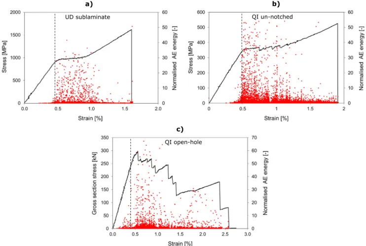
The accumulation of damage was monitored in a few specimens of each configurations with a PAC PCI-2 acoustic emission device at a 5 MHz sampling rate using two WSA type 100–1000 kHz wide- band sensors attached to the specimens with clips and silicone grease as an acoustic coupler. The aim of these measurements was to study the damage initiation in the different specimen con- figurations by detecting LSM ply fragmentation in the 0°sublami- nates as was successfully demonstrated earlier in [45]. Fig. 11 shows typical plots of the acoustic energy normalised to the aver- age event energy for three different T1000/XN-80 configurations.
The vertical dashed lines show the fragmentation initiation esti- mated from the AE signals. Part (a) and (b) reveal very low acoustic activity before the pseudo-yield point for both the UD sublaminate and the un-notched QI configuration, and very strong activity dur- Fig. 9.Full width X-ray CT scans of different type notched specimens after tests interrupted before any stress-drop at the overall strains indicated on the scans. Top view scans show the damage in one of the 0°sublaminates. (For interpretation of the references to colour in this figure legend, the reader is referred to the web version of this article.)
Fig. 10.(a) Post-processed X-ray CT scan showing delamination and splitting of a T1000/XN-80 QI-OH specimen unloaded from 0.58% strain after the first stress-drop and (b) post mortem photographs of QI-OH specimens (edge view). (For interpretation of the references to colour in this figure legend, the reader is referred to the web version of this article.)
ing the plateau in both cases. This confirms that the ply fragmen- tation mechanism is active in multi-directional hybrid laminates in a similar way as in UD hybrids, consistent with all the other results presented.
Fig. 11c indicates that high energy events occurred significantly earlier than the first stress-drop in the QI open-hole specimens, which indicates that local fragmentation took place at the notch before the first delamination. This confirms that the fragmentation mechanism was active locally at the notch and induced load re- distribution, thereby eliminating notch sensitivity.
4. Conclusions
The following conclusions were drawn from the study of thin- ply all-carbon/epoxy hybrid laminates:
Highly non-linear, pseudo-ductile tensile stress-strain response was demonstrated with both quasi-isotropic (QI) laminates due to the fragmentation of the low strain material and stable delamination around the fractures in the 0° direction. There was a significant further increase in stress before the final fail- ure in the case of the un-notched T1000/XN-80 QI-UN hybrid material which can be exploited for warning and as a safety margin in structural applications. The stress-strain response of the MR60/XN-80 QI-UN specimens was also pseudo-ductile
‘‘elastic-perfectly plastic” although the UD sublaminate beha- viour was brittle. The difference was attributed to the role of the off-axis sublaminates in providing extra capacity to carry
load after low strain layer fragmentation and protecting the 0° sublaminates from stress-concentrations at the grips.
Reduced notch sensitivity similar to the ductile net-section behaviour of metals was achieved in both hybrid laminates due to local damage and induced load re-distribution around the notches, for both open holes and sharp notches. Local dam- age accumulation around the notches was confirmed by X-ray CT scans of specimens after interrupted tests.
X-ray CT scans of the quasi-isotropic un-notched specimens indicated very little damage before the pseudo-yield point and only small, local initiation of inter-sublaminate delamination before the first stress-drop (for T1000/XN-80) or before final failure (for MR60/XN-80). These observations can help to estab- lish design and operational limits for the new hybrid laminate configurations.
Acknowledgement
This work was funded under the UK Engineering and Physical Sciences Research Council Programme Grant EP/I02946X/1 on High Performance Ductile Composite Technology in collaboration with Imperial College London. Gergely Czél acknowledges the Hungar- ian Academy of Sciences for funding through the János Bolyai scholarship and the Hungarian National Research, Development and Innovation Office - NKFIH for funding through grants ref. OTKA K 116070 and OTKA PD 121121. The authors acknowledge North TPT for supplying materials for this research. All data required for reproducibility are provided within the paper.
Fig. 11.Graphs showing typical plots of the acoustic event energy normalised to the average AE energy of each test for T1000/XN-80 specimens: (a) UD sublaminate, (b) QI un-notched and (c) QI open-hole specimen. Dashed lines highlight the damage initiation. (For interpretation of the references to colour in this figure legend, the reader is referred to the web version of this article.)
Appendix A. Interlaminar fracture toughness measurements
This section summarises the experimental determination of the mode II fracture toughnessGIICof the interfaces within the sublam- inates of the interlayer hybrid composites used in the paper. The toughness of the different hybrid layer interfaces was important to be determined as the MR60/epoxy prepreg had a different matrix than the T1000 and XN-80/epoxy prepregs. Therefore in the T1000/XN-80 configuration both sides of the interface had the same resin whereas in case of the MR60/XN-80 hybrid the interface was a mix of two different resins. Cut central layer tensile specimens similar to the ones tested in[48]were used, but in the current work the discontinuous ply block was made of a different UD composite material than that used for the continuous plies (seeFig. A1andTable A1). It was not necessary to use end-tabs since there was a sufficient margin between the failure strain of the high strain material (HSM) and the low strain material (LSM), and stable delamination (pull-out of the LSM layer) was expected to start at low strain (i.e. the HSM was designed to be safe against premature fracture at the grips). The ends of the specimens were covered by sandpaper (P80 grit) for protection against the sharp serrated surfaces of the wedge type grips. The nominal sizes of the specimens were 0.77/20/155 mm thickness/width/free length respectively.
The lay-up sequence (seeTable A1) for the T1000/XN-80 mate- rial configuration was a scaled thickness version of the sublami- nate used in the laminates in the paper, whereas the MR60/XN- 80 hybrid was made with an increased HSM proportion to be safe against premature failure. This small modification is not expected to change the fracture toughness. Table A1 shows the lay-up sequences for the two different material configurations. TheGIIC was calculated with Eq.(A1)substituting the strain for delamina- tion initiation into Eq.(1) [28], which was defined as the knee point determined by the intersection of two lines fitted to the initial lin- ear and the plateau part of each individual stress-strain graph of all specimens as shown onFig. A2.
GIIC¼
e
2kneeE2t2ð2E1t1þE2t2Þ8E1t1 ðA1Þ
where
e
kneeis the strain at delamination initiation,E1is the initial modulus of the HSM,E2is the initial modulus of the LSM,t1is the thickness of one HSM layer andt2is the thickness of the LSM layer as shown inFig. A1. Detailed formulation can be found in[49].Tensile tests were executed on a Zwick Z250 type universal electro-mechanical test machine fitted with wedge type mechani- cal grips under displacement control at 4 mm/min crosshead speed. The strains were measured with a Messphysik ME 46 type video extensometer with a 75 mm nominal gauge length. The tests
Fig. A1.Specimen schematic of the cut central layer hybrid specimens (LSM-low strain material, HSM- high strain material).
Fig. A2.Typical stress-strain graphs of the two different tested configurations based on the nominal thickness of the laminates. (For interpretation of the references to colour in this figure legend, the reader is referred to the web version of this article.)
Table A1
Results summary of the fracture toughness tests (8 specimens tested of each configuration).
Lay-up sequence Average measured modulus [GPa] (CV%)/
Predicted modulus
Predicted GIIat 0.5%
strain
Knee point strain
GIICbased on predicted moduli
GIICcorrected for experimental moduli
[GPa] [N/mm] [abs.%] (CV rel.%) [N/mm] [N/mm]
[T10008/XN802]s 190.6 (5.8)/214.9 1.268 0.38 (9.8) 0.732 0.650
[MR6010/XN802]s 181.4 (3.5)/214.2 1.294 0.49 (4.4) 1.246 1.053