Article
Coordination of Lateral Vehicle Control Systems Using Learning-Based Strategies
Balázs Németh
Citation:Németh,B.Coordinationof Lateral Vehicle Control Systems Using Learning-Based Strategies.
Energies 2021, 14, 1291.
https://doi.org/10.3390/en14051291
Academic Editor: Wiseman Yair
Received: 19 January 2021 Accepted: 21 February 2021 Published: 26 February 2021
Publisher’s Note: MDPI stays neu- tral with regard to jurisdictional clai- ms in published maps and institutio- nalaffiliations.
Copyright:© 2021 by the authors. Li- censee MDPI, Basel, Switzerland.
This article is an open access article distributed under the terms and con- ditions of the Creative Commons At- tribution (CC BY) license (https://
creativecommons.org/licenses/by/
4.0/).
Institute for Computer Science and Control (SZTAKI), Eötvös Loránd Research Network (ELKH), 13-17, Kende Utca, H-1111 Budapest, Hungary; balazs.nemeth@sztaki.hu
Abstract:The paper proposes a novel learning-based coordination strategy for lateral control systems of automated vehicles. The motivation of the research is to improve the performance level of the coordinated system compared to the conventional model-based reconfigurable solutions. During vehicle maneuvers, the coordinated control system provides torque vectoring and front-wheel steering angle in order to guarantee the various lateral dynamical performances. The performance specifications are guaranteed on two levels, i.e., primary performances are guaranteed by Linear Parameter Varying (LPV) controllers, while secondary performances (e.g., economy and comfort) are maintained by a reinforcement-learning-based (RL) controller. The coordination of the control systems is carried out by a supervisor. The effectiveness of the proposed coordinated control system is illustrated through high velocity vehicle maneuvers.
Keywords:coordinated control design; autonomous vehicles; learning-based control
1. Introduction and Motivation
The design of intelligent automated road vehicles required the automation of several vehicle, road and transportation systems in the last decade. The automation of the processes through the increased number of sensors and information sources can be made available.
Although the automation of the different systems can improve the performance of the road vehicles, the advantages of the automation through the effective coordination of the subsystems can be achieved. From the aspect of automated vehicles at least three different levels of coordination can be defined, such as on the level of vehicle control systems, on the level of vehicle control and human driving and on the level of vehicle and transportation system. This paper focuses on the coordination on the level of the vehicle control system, but the motivations of all of the previous coordination tasks are briefly introduced below.
The coordination on the level of vehicle control systems means the integration of smart actuators, which have been developed to achieve various automated vehicle functionalities.
For example, the maneuvering of the vehicle through automated steering, torque vectoring, differential braking and variable-geometry suspension can be carried out. Despite the similarities in the functionalities, the operational capability and the cost aspects of each intervention can be different. In the literature, various methods for achieving safe and cost- effective coordination techniques have been developed. The most important challenges are the handling of nonlinearities and uncertainties, the providing of energy-optimal actuator selection strategy and the assessment of the performance issues in automated systems.
The reconfigurable robust parameter-varying methods can provide an effective solution on the design of local controllers for coordinated control systems [1]. Through the scaling of the parameter-dependent weighting functions in the robust control design, the joint intervention of the actuators are feasible and the performance of the control intervention can be guaranteed. Moreover, the reconfiguration can provide a fault-tolerant operation for the vehicle [2,3]. However, a drawback of the reconfiguration-based coordination is that it can be difficult to formulate a provable energy-optimal actuator selection strategy [4]. A further challenge for model-based vehicle control and coordination design is the different
Energies2021,14, 1291. https://doi.org/10.3390/en14051291 https://www.mdpi.com/journal/energies
performance specifications of the vehicle system manufacturers, which can be handled through open source physics models of the vehicle dynamics and driver assistant system command models [5]. A special topic in the field of vehicle control coordination is linked to electric vehicles, where coordination means the handling of independent in-wheel electric driving systems [6]. Through coordination, the cruise control and the lateral control functionalities can be achieved [7].
The challenge of coordination on the level of vehicle control and human driving appears through the cooperation between semi-autonomous vehicle systems and human drivers. Thus, the developed vehicle control solutions must guarantee its cooperation with the human intervention, i.e., during the operation of partially automated systems the intentions and interventions capabilities of the driver must be considered. The limited human capability must be considered especially in the operation transfer between the automated driving system and the human driving [8,9]. Moreover, several control systems actuate together with the driver, e.g., active steering systems can provide additional steering angle to the intervention of the driver [10,11]. The coordination of the human intervention and the operation of the vehicle control systems requires knowledge on the driving style and capability of the driver, which has motivated the research on the modeling of the human driver [12,13]. The modeling of human driving capability can also provide information for the design of autonomous steering systems [14].
Furthermore, the integration of automated vehicles in an intelligent transportation system provides novel performance requirements on the vehicle level. It leads to the chal- lenge of coordination on the level of vehicle and transportation systems. The performances on the level of transportation are typically the minimization of traveling time and energy consumption for the vehicles in a given traffic network, i.e., the avoidance of traffic jams and insufficient stop-and-go scenarios. It requests the coordination of the vehicles’ motion and similarly, the predefined vehicle motion on the vehicle level must be carried out [15].
Thus, the coordination of the vehicle control systems can improve the performances on the local and on the global levels simultaneously [16]. The coordination on the level of vehicle and transportation systems are incorporated into, not only the handling of vehicle actuators, but also the handling of transportation system interventions. For example, the coordination of vehicle cruise control and traffic light interventions can provide energy- efficient motion for the automated vehicles, which has benefits on the performance level of the entire traffic flow [17]. The coordination can be carried out on the level of network, e.g., in [18] a coordination strategy is applied for public transport services. Another hot topic is the coordination of vehicles and transportation systems in intersection scenarios, where the effectiveness of the operation through optimal coordination of interventions can be achieved [19,20].
The classical model-based control design and coordination approaches are able to provide appropriate performance levels in the case of all three levels of coordination. Never- theless, the novel data-driven and learning-based approaches have promising results in the field of vehicle automation. The main benefit of the learning-based approaches is that the performance level of the control might be improved through the high number of training scenarios. For example, in the local control design of a vehicle actuator, the model of the systems must be known. Nevertheless, in practice, the actuators contain nonlinearities and uncertainties, which can lead to robust control design methods. Guaranteeing robustness under the increased uncertainty domain can result in low-performance level. Similarly, if the state space representation of the system contains a high number of states, the design process can be numerically difficult, which can also lead to a solution with a reduced per- formance level. Consequently, the model-based solutions can have conservative property, also in the design of the coordination strategy. In contrast, learning-based approaches can help to improve the performance level through the training of the complex agents, e.g., neural networks in the control and in the coordination process [21]. Nevertheless, the challenge for the learning-based methods is the assessment of their resulted performance, i.e., proving guarantees on the minimum performance level [22,23]. It can be fruitful to find
methods for the coordination of vehicle control systems, with which the advantages of the model-based and the learning-based methods can be preserved, while the drawbacks can be eliminated, i.e., ensuring a minimum performance level and similarly, while the achiev- able performance level is maximized. In [24] an iterative learning-based model predictive control (MPC) method is proposed, in which the terminal cost and set for the model-based control is learned. Another example is found in [25], where the Linear Parameter-Varying (LPV) method for the design of a safe control next to the learning-based controller is used.
Moreover, the learning features can have an impact on the formulation of control-oriented state-space models, see e.g., [26]. In spite of the promising result, a design method for vehicle system coordination using joint learning-based and model-based cannot be found, to the best of the author’s knowledge.
The goal of this paper is to provide a coordination method for vehicle control systems on the vehicle level, which is able to combine the advantages of learning-based and model-based approaches. Thus, the proposed method guarantees minimum performance level on selected control performances, while an increased maximum performance level during the operation of the coordinated control system can be achieved. The coordination method is presented in the context of lateral control design for automated vehicles. The contribution of the paper is a control design method for steering and torque vectoring, with which the energy-optimal coordination of the actuation is achieved, while the minimum level of selected safety performances through the design method are guaranteed. The design is based on the joint application of the robust LPV and the reinforcement learning (RL) methods. The aim of the robust LPV method is to guarantee the minimum level of selected safety performances and the role of the RL method is to maximize the level of all performances.
The paper introduces the design process as follows. In Section2the performance specifications for lateral vehicle control and their incorporation in the control framework are presented. The design of the robust LPV control and the RL-based control are proposed in Section3. The effectiveness of the resulted coordinated control system is illustrated in Section4. Finally, in Section5the results are concluded and some future challenges regarding the proposed method are discussed.
2. Performance Specifications and Control Framework
Control performance specifications have high importance in the coordination of the actuators on the vehicle level. There can be strict performance specifications, which during the entire operation of the vehicle control system must be guaranteed. In the context of automated vehicle control, these are the safety performance specifications, e.g., the limitations on the path or velocity tracking errors. The strict performance specifications can result from the physical limitations of the actuators, such as the maximum torque of an actuator or the limited achievable steering angle. In this paper, the group of the strict performances are called primary performances.
Furthermore, there is another type of performance specification, which it is recom- mended to maintain. However, there can be critical situations during the operation of the control system, when these performance specifications can be violated. Since primary performances have priorities, in these situations the controller focuses on the guaranteeing of them. In case of automated vehicles, these performance specifications are typically the economy and comfort specifications, e.g., the minimization of the energy consumption or the maximization of the traveling comfort. The group of these performances are called secondary performances.
This paper focuses on the coordinated control design of lateral vehicle interventions, i.e., the coordination of steering and torque vectoring interventions. The automated steering intervention without human driver actuation on the front wheels of the vehicle is achieved.
The torque vectoring is considered to be realized by the differential electric driving also on the front wheels. It is also considered that the rear wheels also can be driven and thus, the velocity tracking functionality of the vehicle is achieved through the traction force
compensation by the same forces on the rear wheels. Thus, the performance specifications against the coordinated control system in the context of the actual problem are formed.
The primary performance specifications in the design process of the control system is as follows.
• The goal of the coordinated control system is to guarantee the tracking of a predefined path for the automated vehicle. Due to safety reasons the tracking error must be limited, with which the keeping of the actual lane can be guaranteed. Thus, a primary performance for the control design is formed as
z1=yre f −y, (1)
wherez1represents the definition of the performance,yre f is the requested reference of the path and y is the lateral position of the vehicle. The specification on (1) is formed as
|z1| ≤z1,max, (2)
wherez1,maxrepresents the predefined maximum path tracking error.
• Due to the physical limits of the steering control intervention, the steering angle on the front wheels must be limited. Thus, a further primary performancez2is defined as
z2=δ, (3)
whereδis the steering angle on the front wheel and the specification is formed as
|z2| ≤z2,max, (4)
wherez2,maxrepresents the maximum of the steering intervention.
• The limitation of torque vectoring has at least two reasons. First, the electric-driven wheels have limitations on the torque actuation, which means that the intervention has physical limits. Second, the driving torque has limits due to the avoidance of the wheel skidding, i.e., the limitation of the longitudinal slip. Therefore, the achievable torque value from the torque vectoring must be limited, which leads to the definition of performancez3, such as
z3= Mvect, (5)
whereMvect represents the torque around the vertical axes of the vehicle center of gravity, which resulted in the differential driving on the front wheels. The primary performance specification is formed as
|z3| ≤z3,max, (6)
wherez3,max is the limitation on the torque vectoring. Since it is necessary to avoid the skidding of the wheel, the selection ofz3,max can depend on the operation of the vehicle, e.g.,z3,maxcan be different for a conventional passenger car and for an off-road vehicle. In the proposed methodz3,max is considered to be a constant value during the operation of the vehicle, and thus, its selection can be influenced by the operation circumstances of the vehicle.
The secondary specifications in the design of the coordinated control are related to the economy and comfort requirements.
• Due to energy management aspects on the vehicle level, the minimization of the control interventions are recommended. It is related the the performancesz2andz3, such as
|z2| →min, (7a)
|z3| →min. (7b)
The minimization of|z2|and|z3|are not independent from each other. Since through δand alsoMvectthe lateral motion of the vehicle can be carried out, it is requested to find a balance between their intervention. In spite of the similarities between the actuation ofδandMvect, they can also have different impacts. The intervention of Mvectmodifies the longitudinal slip on the front wheels and it can have an influence on the longitudinal dynamics. Moreover, the intervention throughδcan require less electric power, but the steering of the front wheels can also modify the longitudinal dynamics slightly. The role of the coordination is to find an optimal balance between the intervention ofδandMvect, which can be a difficult task through purely model- based principles.
• The comfort has high importance in the operation of the automated vehicle control systems, because it has relevance from the aspect of the passengers. The lateral control systems can improve the traveling comfort through the minimization of the lateral jerk [27], such as
z4=a˙y, (8)
wherez4represents the definition of the performance on the jerk,ay=y¨is the lateral acceleration of the vehicle. Thus, the performance specification is the minimization of z4such as
|z4| →min. (9)
The primary and secondary performance specifications show that there are some overlapping between some performances. In (4) and in (6) the absolute values ofδandMvect
are limited, while in (7) their absolute values are minimized. The primary performance specifications are formed as hard constraints, while the secondary specifications are soft constraints. However, it is possible to handle all of these constraints in the model-based control design. For example, in case of an MPC design, the cost function contains the secondary specifications and the optimization constraints the primary specifications. In the reconfigurable robust LPV design of this paper the minimization on (7) is incorporated in the control design, and the constraints (4) and (6) are incorporated in the coordination strategy through the actuator selection method [4]. Nevertheless, the coordination in (7) can be difficult in the model-based strategies. Moreover, the extension of the vehicle dynamics with the lateral jerk can also provide difficulties in the control design due to the increase of the state vector. Therefore, maintaining the secondary performances motivates the tuning of the coordinated control through RL.
In the rest of this section a control design framework is proposed, with which primary and secondary performances through different techniques can be considered. Since the primary performances have priorities against further performances, and they must be guaranteed during the entire operation of the system, the primary performances are considered in the robust LPV coordinated control design, because it provides theoretical guarantees on the achieved primary performance level [1]. Thus, (2) is incorporated in the control design and (4) and (6) in the coordination strategy. Although the LPV design also involves the secondary performance specifications (7), it can be effectively incorporated in the RL-based control design. Thus, the role of the RL-based controller is to improve the primary performance (2) and the secondary performances (7) and (9).
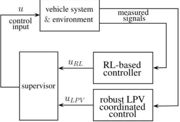
The framework for the coordinated control design is illustrated in Figure1. During the control design process, the robust LPV controllers for the steering and the torque vectoring interventions, together with the actuator selection coordination strategy in the first step are designed. Then, in the second step, the multiple output learning-based agent is trained through several numbers of episodes in an RL process. In the training process, the LPV-based coordinated control and the supervisor are used. The role of the supervisor is to guarantee that the control input vectoru= [δ, Mvect]Tis always inside of a predefined environment ofuLPV = [δLPV, Mvect,LPV]T. Thus, the output of the RL-based controller uRL= [δRL, Mvect,RL]Tis not able to violate the primary performance specifications.
vehicle system
&environment
RL-based controller
measured signals control
input
robust LPV coordinated supervisor
control u
uRL
uLP V
Figure 1.Framework for coordinated control design.
3. Design of the Elements in the Control Framework
The goal of this section is to propose the design of the elements in the control frame- work of Figure1, i.e., the supervisor, the coordinated LPV controller and the RL-based con- troller.
3.1. Formulation of the Supervisory Strategy
Firstly, the formulation of the supervisory strategy is proposed, which can help to understand the concept behind the design of the two control elements. The goal of the supervisor is to provide control inputu= [δ, Mvect]Tbased on the signals of the RL-based and the robust LPV controllers.
The concept of the design is that the robust LPV-based coordinated control is able to guarantee primary performance and some of the secondary performance specifications under all vehicle dynamic scenarios. Thus, u = uLPV can be a suitable input for the automated vehicle. Nevertheless, the level of the secondary performances can be improved withu=uRLunder several vehicle dynamic scenarios. Therefore, it is necessary to find a supervisory strategy, with which the benefits ofuLPVanduRLcan be achieved.
The idea behind the supervisory strategy is thatucan differ fromuLPVin a limited domain∆max = [∆max,δ, ∆max,M]T, and the primary performances are guaranteed in the en- tire range ofuLPV±∆max. Thus, ifuRLis inside of the domain[uLPV−∆max;uLPV+∆max], the selection ofu=uRLis acceptable, because the primary performance specifications are guaranteed, and the secondary performances can be improved.
The supervisoryuselection strategy, which is embedded in the supervisor, is formed as an optimization problem, such as
min∆ δ−δRL2
+Q Mvect−Mvect,RL2
(10a) subject to
∆∈∆max, (10b)
where the role of the scalarQis to unify steering and torque vectoring actuation due to their different units and values.∆max = [∆δ, ∆M]Tis resulted by the relationship
u=uLPV+∆=
δLPV
Mvect,LPV
+
∆δ
∆M
, (11)
and where∆represents the actual bounded difference ofufromuLPV. The optimization problem (10) expresses that it is suggested to track the control input signaluRLthroughu, but the tracking must be limited by∆maxto preserve guarantees on primary performance specifications. Using (11), the cost function in (10a) can be transformed as
δLPV+∆δ−δRL2
+Q Mvect,LPV+∆M−Mvect,RL2
=
=∆T 1 0
0 Q
∆+2
1 0
0 Q
∆(uLPV−uRL) + (uLPV−uRL)T
1 0
0 Q
(uLPV−uRL), (12) which shows that only the first and the second terms depend on the optimization variable∆.
Thus, the third term during the optimization can be omitted, which means that the control input selection strategy in the supervisor is formulated as a constrained optimization problem, such as
min∆ ∆T
1 0
0 Q
∆+2
1 0
0 Q
∆(uLPV−uRL) (13a) subject to
∆∈∆max. (13b)
The result of the optimization is∆, from whichu is computed through (11). The optimization problem is solved online during the operation of the control system.
3.2. Introduction to Robust LPV-Based Design for Coordinated Lateral Vehicle Control
The role of the robust LPV-based coordinated control is to provide control signal uLPV, with which the primary performance specifications during the entire operation of the system is guaranteed. The LPV-based control design is based on the existing results in the field of vehicle control coordination, see [1,4]. Thus, in this paper, the concept of the LPV-based coordinated control design is briefly introduced. Furthermore, the extension of the existing results concerning the proposed design framework in Figure1is presented.
The LPV-based coordinated control design is based on a reconfiguration method, which contains local controllers for each actuators and an actuator selection strategy. Each local controller, e.g., for steering and torque vectoring functionalities are designed based on the dynamic lateral model of the vehicle [28], such as
Jψ¨=C1α1l1−C2α2l2+Mvect, (14a) mv(β˙+ψ˙) =C1α1+C2α2, (14b)
¨
y=m(β˙+ψ˙), (14c)
where J,mare the inertia and mass values of the vehicle,l1,l2are the lateral distances between the center of gravity and the front/rear axles,C1,C2are the cornering stiffness values on the front and the rear axles. The front/rear lateral slip values are formulated as α1=δ−β−ψl˙v1,α2=−β+ψl˙v2, where ˙ψis the yaw-rate,βis the side-slip of the vehicle andvrepresents longitudinal velocity. The dynamic formulation of the lateral vehicle motion can be transformed to a state space representation, such as
˙
x=A(v)x+B(v)u, (15)
where the state vector isx= [ψ,˙ β, ˙y, y]TandA(v),B(v)are velocity-dependent matrices.
In the design of the robust LPV controllers the variation betweenuLPVanduis considered as a robustness issue. The bound of the variation of the control inputs∆maxis built in the control design as an input additive uncertainty, which transforms (15) through (11) as
˙
x= A(v)x+B(v)∆+B(v)uLPV, (16) where∆is a disturbance signal. In the LPV-based design,∆is handled as an unknown uncertainty. However, in practice,∆is computed by the supervisor, but this information is not used in the design. A future challenge of the LPV-based design can be the handling of∆as a known uncertainty, with which the conservativeness of the resulted controller can be reduced. Nevertheless, in the current design process the bound of∆, i.e.,∆maxis incorporated in the weighting function on the signal∆.
In the design of the local controllers forδLPVandMvect,LPVinterventions the primary performance of lateral errorz1and the secondary performance specifications on the mini- mization ofz2,z3, i.e., the control interventions are considered. The primary performance specification onz1(2) is guaranteed through a minimization, such as
|z1| →min. (17)
Although (17) is an objective in the control design, while (2) is a constraint, in the practice of the LPV-based design the controller can be effectively tuned to achieve a suitable approximation. In the weighting strategy of the LPV-based control design, it is possible to incorporate in the specificationz1,maxon|z1|through a weighting function. Although the hard constraint is transformed to a soft constraint, in practice the original performance specification onz1can be guaranteed. The details on the selection strategy of the weighting function are found in [1,4]. Thus, the control design problem contains the minimization- based performance specifications (17) and (7).
The reconfiguration strategy between the control interventions requires the possibility to scale the control interventions individually. It is carried out by parameter-dependent weighting functions on the performancesz2andz3. It means that scheduling variables ρδandρMare defined, whose values can vary between 0 and 1. For example, ifρδ=0 is selected then steering intervention is deactivated, whileρδ =1 represents fully activation and the selection of 0 < ρδ < 1 is related to partial activation. In the reconfiguration strategy each intervention throughρδ,ρMcan be independently activated.
Thus, two independent controllers are designed, one is related toδLPVand another is related toMvect,LPV. In case of a steering controller, two scheduling variables are incorpo- rated in the design, such asvandρδ, and in the case of torque vectoring the scheduling variables arev andρM. In the rest of this paper, the set of the scheduling variables is represented withρ∈$, but it has different meanings for each controller. Similarly, in case of the steering control designMvect,LPV,∆Mare not considered, and in the design of torque vectoring controlδLPV,∆δare omitted. Therefore,wrepresents∆δin the steering control design and it represents∆Mfor torque vectoring. The measured signals of both controllers are the same, such as the lateral error of the vehicleey=yre f−y.
The goal of the LPV-based control design is to guarantee the quadratic stability of the closed-loop system. Simultaneously, the inducedL2normγfrom the disturbancewto z= [z1, z2, z3]Tis guaranteed to be less than 1. The stability and the performance level of the closed-loop system are guaranteed by the design procedure [29,30]. The control design leads to the selection of a parameter-varying controllerK(ρ,ey), whose output vector contains steering and torque vectoring interventions. It results in a minimization problem, such as:
K(ρ,einfy)sup
ρ∈$ sup
kwk26=0, w∈ L2
kzk2
kwk2, (18)
where the results of the two independent minimization tasks are K(ρδ,v,ey) steering controller andK(ρM,v,ey)torque vectoring controller.
The coordination of the resulted LPV controllers are achieved by an actuator selection strategy, which is mathematically represented by the functionF. The outputs ofF are ρδandρM, which are the scheduling variables of each controller. The inputs ofF are the interventionsδ,Mvectand further vehicle dynamic signals, e.g., the longitudinal velocity or slip values of the front wheels. The primary performance specifications (4) and (6) are guaranteed throughF. For example, ifδLPV is close toδmax, thenρδis reduced, which results in less activation for the steering intervention and thus, (4) is guaranteed. The advantage of the incorporation of the longitudinal slip values in the actuator selection strategy is that the skidding of the wheels can be avoided. If the longitudinal slips are monitored, the torque intervention on the wheels can be reduced through the decrease of ρM, which leads to reduced longitudinal slip.
The form of the functionFcan be determined through model-based analysis, econom- ical and empirical considerations. A method for the analysis of the vehicle dynamics to formulate a coordination strategy can be found in [4]. For example, under normal vehicle dynamic conditions the steering intervention can be preferred against torque vectoring due to economy reasons, which is expressed through the selection ofρδandρM. In that study, the fastness of the interventions has also been examined and it has been stated that differential braking and torque vectoring can be advantageous at high velocities. Formally, F through piecewise linear functions can be formed, whose results are the actualρδ,ρM
values. The method for the selection ofFand the details on the mathematical formulation of the empirical considerations can be found in [1].
The results of the LPV-based coordinated control design are two independent steering and torque vectoring controllers and the actuator selection strategyFfor their coordination.
The coordinated control strategy is able to provide guarantees on the primary performance specifications, and some of the secondary performances are maintained. However, during the LPV-based coordinated control design, it can be difficult to formulate and improve some secondary performances, i.e., in this paper,z4is not improved. Moreover, the control design can result in conservativeness through the operation of the vehicle control system, e.g., it can be difficult to manage the advanced reduction of the control interventions.
Moreover, the formulation ofF can contain several simplifications, which can result in reduced performance level on secondary performances. It motivates the extension of the control strategy with the RL-based coordinated design.
3.3. Design of RL-Based Coordinated Control
The goal of the RL-based coordinated control is to provide the improvement of the secondary performances, i.e., the comfort and economy performances. In this paper, it is achieved through a neural network with the outputuRL. The neural network is trained via an RL process through several episodes.
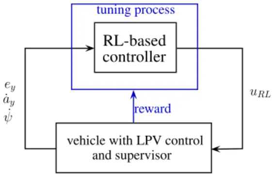
In the training process, the previously designed robust LPV-based coordinated control and the supervisor are incorporated. The structure of the RL process is shown in Figure 2. The environment for the training process, i.e., vehicle with LPV control and supervisor provides guaranteed minimum performance level on primary performances, independently fromuRL. The goal of the RL process is to improve the achievable maximum performance for all performances. The measured signals of the RL-based controller are path tracking error, lateral jerk and yaw-rate. The tuning process of the parameters in the multiple output neural network is based on a reward cost functionr, which contains some primary and secondary performances, such as
r=Q1
∑
n i=1z21(k) +Q2
∑
n i=1z22(k) +Q3
∑
n i=1z23(k) +Q4
∑
n i=1z24(k), (19)
whereQ1,Q2,Q3andQ4scalar negative values are design parameters, which scale the importance of each terms and the balance between them. In (19) the valuenrepresents the
number of samples of a given episode andkis its index. The reason of selecting the terms ofris the following.
• The performance specification on z1is guaranteed by the robust LPV-based coor- dinated control, which leads to a guaranteed minimum performance level on z1. However, it is beneficial to take part in the reward, because the maximization of the further performances(z2,z3,z4)inrcan lead to auRLsignal, which might often violate (2). Thus, for avoiding the violation, the optimization in the supervisor can result inu6=uRL. It means that it can be rarely found∆, with whichu−uRLis close to zero due to the saturation of∆by∆max. Consequently, the benefits of the RL-based controller, i.e., the improved performance level onz2,z3,z4can be often lost. Therefore, the incorporation ofz1inris recommended.
• The minimization of the control interventions are secondary performance require- ments, see (7). The balance between steering and torque vectoring interventions are set byQ2andQ3weights. For finding adequate control interventions, a high number of episodes with various vehicle dynamic scenarios during the training process is performed. Through the training under the various scenarios, the intervention capa- bilities of the actuators can be met, whose experiences are built in the design of the RL-based controller. It provides a high advantage from the aspect of the intervention coordination, compared to the actuator selection strategy in the LPV-based design, whereFis resulted by simplified relations.
• The minimization of the lateral jerk is a performance specification (9), which only in the RL-based controller formulation is incorporated. Thus, the resulted controller is able to improve the comfort criteria, compared to the LPV-based coordinated controller.
The reward Function (19) shows that its maximum value might be zero, if all of the quadratic terms have zero value. Nevertheless, zero is a theoretical maximum, because it is not possible to reduce to zero all performances a the same time. Thus, the maximum reward leads to the best achievable maximum performance level. The selection ofQivalues for achieving the maximum performance level has two aspects. First, it is necessary to selectQi values, with which the different performances can be compared. For example, path tracking error is around±0.03 m, whileMvectis between±5000 Nm . Therefore, it is necessary to select a high|Q1|value forz21and a low|Q3|value forz23. Second, the selection ofQimust express the relative importance of each performance, with which the priorities can be guaranteed.
RL-based controller
vehicle with LPV control and supervisor
uRL
ey
˙ ay
ψ˙ reward
tuning process
Figure 2.Control structure in the learning process.
The goal of the reinforcement learning process is to maximize reward (19) during episodes. In this paper the training process through a deep deterministic policy gradient (DDPG) method is carried out, which is a model-free, online, off-policy RL method, see [31].
A DDPG agent is an actor-critic reinforcement learning agent that computes an optimal policy, which is able to maximize the long-term reward. In the applied method, actor and critical approximators are used. Both approximators use the observationsey, ˙ay, ˙ψ,v, which are represented byS. The purpose of the actor approximatorµ(S)is to find the actionA
withuRL, which maximizes the long-term future reward. The role of the criticQ(S,A)is to find the expected value of the long-term future reward for the task.
The result of the learning process is an RL-based controller, which is able to maximize the performance level ofz1,z2,z3,z4through its control interventionuRL. The achieved neural network can be implemented in the control structure in Figure1directly.
Remark that an advantage of the proposed RL-based design method is that the con- trolled system can be used even under the training process, because the primary perfor- mances are guaranteed in every episodes. Nevertheless, the maximum performance level of the system can be low at the beginning of the training. As a consequence, it provides the capability to improve the performance level of the system during the entire life cycle of the automated vehicle. It means that after an initial learning phase the vehicle system can be op- erated and simultaneously, the signals in the actuation, the reward and the observation can be logged, which can serve for further training. In case of service occasions the RL-based controller can be updated, which can lead to the improvement of the performance level.
However, the elaboration of the entire logging, training and updating process together with its infrastructural and cyber-security concerns is a future challenge, which is out of the scope of this paper.
4. Illustration of the Control Efficiency
In this section, the effectiveness of the proposed control algorithm through simulation examples is illustrated. The examples present vehicle dynamic scenarios, in which the pro- posed coordinated control structure is used. It is compared with further simulations, which are related to the preliminary results of the learning, i.e., the training has been stopped at a given episode. The goal of the illustration is to show that the secondary performances, especiallyz4can be improved through the proposed coordinated control structure, and simultaneously, the primary performance specifications are guaranteed. Thus, accurate path tracking with the consideration of limited coordinated control intervention and with improved traveling comfort can be achieved.
During the design of the control system, two optimization problems must be offline solved. The design of the robust LPV controller requires the offline solution of the opti- mization problem (18), which is carried out through an LPV Toolbox for Matlab, see [32].
The design of the controller requires low computation time, e.g., under 30s. The other optimization process is required by reinforcement learning. It can have high computation time, because it requests the running of a high number of scenarios. Thus, it highly depends on the complexity of the vehicle dynamic model and the traffic environment. In the recent paper the performing of 120 scenarios together with the optimization process between each scenario requests around 1 h with Matlab 2020a Reinforcement Learning Toolbox [33] on Intel i7 CPU.
In the learning process of the RL-based controller the neural networks with the following structures have been trained. The actor network has six neurons in the input layer, three fully connected layers with 48 neurons and Rectified Linear Unit (ReLU) functions in each layers and three neurons with hyperbolic tangent functions in the output layer. The critic network has the same structure, but it has a further input, such as the action itself in the previous step. The sampling time in each episode is selected toT=0.01 s and 120 episodes are carried out. The terms in the reward function are considered with the same design parameters, such asQ1=−1,Q2=−10,Q3=−10−10andQ4=−5000.
The 40slong scenarios for the training are generated as follows. The longitudinal velocity of the vehicle is selected in the form of a sinusoidal signal, whose bias, amplitude and frequency values are selected randomly. Thus, the velocity of the vehicle can vary between 30 km/h . . .130 km/h and its frequency can be between 0.01 . . . 2 Hz, which covers the representation of slight motion and powerful maneuvering scenarios. The reference signalyre f for the vehicle is composed as a complex signal, which contains chirp, step and ramp signal elements. In the scenarios, the amplitude of the step signal and the slope of the ramp has been also selected randomly, for covering a high variety of the signals.
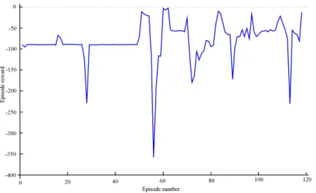
The achieved value of the reward function in each scenario is illustrated in Figure3. It can be seen that the value of the cumulative reward to the end of the training process is significantly increased, i.e., from−100 to−7. The illustration shows the convergence of the function, even if reduced values during the training process are achieved.
Figure 3.Illustration of the cumulative reward values.
The effectiveness of the resulted control algorithm on a comparative example is pre- sented. In the example two scenarios are compared, i.e., the robust LPV-based coordinated control and the proposed learning-based coordination (in the legends of the figures LPV and LPV-RL, respectively). The vehicle moves along a curvy trajectory, especially at the end of the scenarios a hook-motion is performed, see Figure4a. The velocity of the vehicle during the simulation in a high range between 80 . . . 150 km/h is varied, see Figure4b.
The primary performancez1, i.e., the tracking error of the path can be evaluated through Figure4c. It shows that the error has low values in both scenarios, the performance is not degraded through the RL-based controller, which means that the minimum performance level|z1|<0.2 m is guaranteed. Nevertheless, the secondary performancez4specification, i.e., the minimization of the lateral jerk is improved. Figure4d shows that the peak values of the jerk signal are reduced by the proposedLPV−RLcontroller, which is around 15%
reduction, see e.g., the section between 0 . . . 400 m. Thus, the results in Figure4shows that the proposed coordinated control design algorithm has a guaranteed minimum primary performance level on the tracking error, while the secondary performance jerk is improved due to the training.
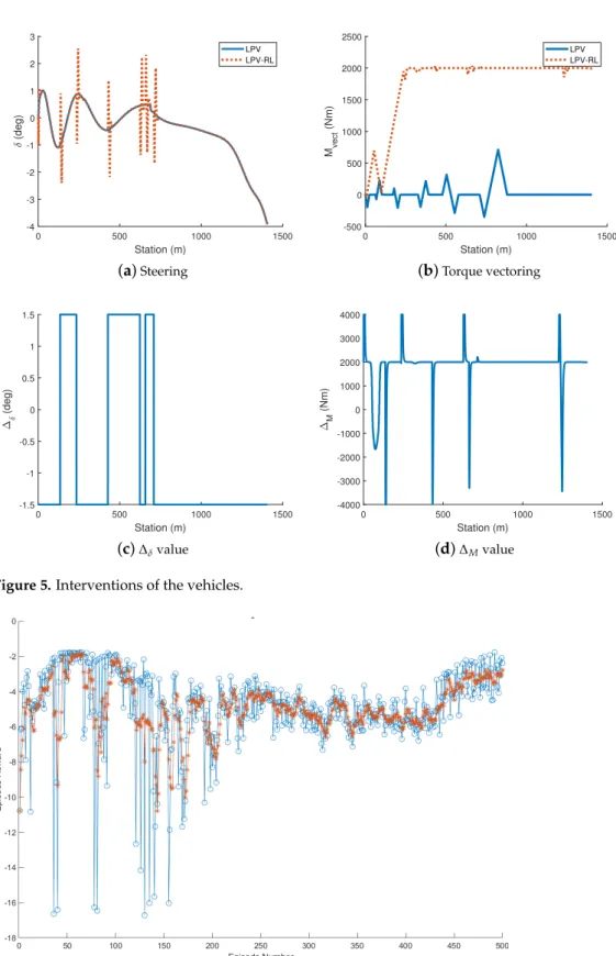
The control interventions are illustrated in Figure5. The steering and torque vectoring interventions for both scenarios are found in Figure5a,b. It can be seen that the signals ofδ are close to each other, but∆δ(Figure5c) can cause abrupt changes in the steering signal.
The torque-vectoring intervention differs in the two scenarios. Due to∆M (Figure5d) the interventionMvectis increased with around 2000 Nm, but in both scenarios the limit z3,max =5000 Nm is not violated, similarly to the primary performance specification on z2. The increased torque vectoring intervention resulted that|z1|is kept belowz1,max, see Figure4a, while the abrupt changes inδandMvecthave role in the reduction of jerk.
0 200 400 600 800 1000 1200 X (m)
0 200 400 600 800
Y (m)
(a)Vehicle trajectory
0 500 1000 1500
Station (m) 80
90 100 110 120 130 140 150
Velocity (km/h)
(b)Velocity
0 500 1000 1500
Station (m) -0.03
-0.02 -0.01 0 0.01 0.02 0.03
ey (m)
LPV LPV-RL
(c)Tracking error
0 500 1000 1500
Station (m) -15
-10 -5 0 5 10 15
LPV LPV-RL
(d)Lateral jerk Figure 4.Results of the simulation scenario.
In the rest of the paper the results of another vehicle dynamic scenario is presented. In this example the the vehicle travels along a simplified road section with constant velocity 50km/h. Moreover, in this example the reward function (19) is extended with a further comfort factor, i.e., lateral accelerationay, such as
r=Q1
∑
n i=1z21(k) +Q2
∑
n i=1z22(k) +Q3
∑
n i=1z23(k) +Q4
∑
n i=1z24(k) +Q5
∑
n i=1z25(k), (20)
wherez5=ayandQ5<0 weight is related to the minimization of the lateral acceleration.
The motivation of consideringz5is that in several comfort objectives lateral jerk and lateral acceleration are simultaneously incorporated in, see e.g., ISO 2631 [34] and UIC ride quality note [35]. Thus, in this example a new training process for achieving RL-based controller has been performed. The illustration of the cumulative reward can be seen in Figure6. It shows that the reward has an increasing tendency with reducing variation, which is the consequence of the improvement of the agent during the training process.
0 500 1000 1500 Station (m)
-4 -3 -2 -1 0 1 2 3
(deg)
LPV LPV-RL
(a)Steering
0 500 1000 1500
Station (m) -500
0 500 1000 1500 2000 2500
Mvect (Nm)
LPV LPV-RL
(b)Torque vectoring
0 500 1000 1500
Station (m) -1.5
-1 -0.5 0 0.5 1 1.5
(deg)
(c)∆δvalue
0 500 1000 1500
Station (m) -4000
-3000 -2000 -1000 0 1000 2000 3000 4000
M (Nm)
(d)∆Mvalue Figure 5.Interventions of the vehicles.
Figure 6. Illustration of the cumulative values for the extended reward (blue: actual, orange:
rolling average).
Some vehicle dynamic signals on the second simulation scenario are found in Figure7.
In this example, the vehicle travels the curvy road section, which is illustrated in Figure7a.
The lateral errors with the LPV-based controller and the proposed learning-based coordi- nated controller are found in Figure7b. It can be seen that in this scenario the reduction of the lateral acceleration (Figure7c) and the lateral jerk (Figure7d) requires increasedey.
Nevertheless, the value ofeyis acceptable due to the performance requirements onz1. The control inputsδandMvectare shown in Figure7e,f.
The results of the simulation through the factors of the international standard ISO 2631 and UIC ride quality note are compared. The computation of the factor in ISO 2631 is based on a frequency weighted root mean square on the lateral acceleration data [34]. The computation of the UIC ride quality note is based on the statistics of the lateral acceleration and lateral jerk signals, i.e., the 50th and 95th percentiles. The comparison of the results show that 15% reduction on the ISO factor and 53% reduction on the UIC factor can be achieved. This improvement resulted in the reduction of the lateral acceleration at the end of the simulation scenario. Although it leads to increasing lateral tracking error, its limitation through the design of the LPV-based controller is achieved.
0 10 20 30 40 50
X (m) 0
20 40 60 80 100
Y (m)
(a)Reference vehicle trajectory
0 20 40 60 80 100 120
Station (m) -0.05
0 0.05 0.1 0.15 0.2
ey (m)
(b)Tracking error
0 20 40 60 80 100 120
Station (m) -10
-5 0 5 10
ay (m/s2)
LPV LPV-RL
(c)Lateral acceleration
0 20 40 60 80 100 120
Station (m) -10
-8 -6 -4 -2 0 2 4
LPV LPV-RL
(d)Lateral jerk
0 20 40 60 80 100 120
Station (m) -4
-3 -2 -1 0 1 2 3 4 5
(deg)
LPV LPV-RL
(e)Steering
0 20 40 60 80 100 120
Station (m) -1000
-800 -600 -400 -200 0 200 400 600 800
Mvect (Nm)
(f)Torque vectoring Figure 7.Simulation results with extended reward.
5. Conclusions
This paper proposed a novel method for the coordination of vehicle control systems.
The effectiveness of the design method through simulation examples is presented. The comparison of the scenarios illustrated that the resulted coordinated control is able to im- prove the secondary performances of the controlled system, and meanwhile, the minimum primary performance level of the system is guaranteed. The resulted vehicle control system is able to operate with increased performance level under high velocity and powerful maneuvering, which is achieved through the various training scenarios.
The provided coordinated control design framework provides several future chal- lenges in the field of automated vehicle control. The proposed design framework contains fixed LPV controllers and coordination strategy, which means that these elements are unchangeable during the training process of the RL-based controller. Nevertheless, it might be fruitful to modify the LPV-based controller and the coordination strategy through a parallel learning process. For example, the parameters of the control-oriented model can be adapted to their real values, and thus, the results of this paper and of [26] can be composed.
Another example of the extension is to provide a training process for the setting of∆max, which can be formed as a variable, see the results of [25]. Moreover, the variety in the fields of applications also provides future challenges. The necessity of learning-based control elements in further coordination levels existed, e.g., in the level of human–vehicle intervention coordination and in the coordination of automated vehicle and transportation system. For example, the advanced transportation control systems contain several data- driven prediction and learning-based route selection algorithms, which have an impact on the actuator intervention on the vehicle level. Moreover, the coupling effect between the different vehicle dynamics, e.g., lateral and longitudinal tire forces, motivates the coordinated design of several vehicle control subsystems. Thus, the provided coordinated control design framework can have advances in various application fields.
Funding:The research was supported by the Ministry of Innovation and Technology NRDI Office within the framework of the Autonomous Systems National Laboratory Program. The research was partially supported by the National Research, Development and Innovation Office (NKFIH) under OTKA Grant Agreement No. K 135512. The work of Balázs Németh was partially supported by the János Bolyai Research Scholarship of the Hungarian Academy of Sciences and the ÚNKP-20-5 New National Excellence Program of the Ministry for Innovation and Technology from the source of the National Research, Development and Innovation Fund.
Conflicts of Interest:The authors declare no conflict of interest.
References
1. Gáspár, P.; Szabó, Z.; Bokor, J.; Németh, B.Robust Control Design for Active Driver Assistance Systems; Springer: Berlin/Heidelberg, Germany, 2017.
2. Gáspár, P.; Németh, B. Set-Based Actuator Reconfguration Analysis for the Integrated Control of Lateral Vehicle Dynamics.
In Proceedings of the 9th IFAC Symposium on Fault Detection, Supervision andSafety for Technical Processes SAFEPROCESS, Paris, France, 2–4 September 2015.
3. Ataei, M.; Khajepour, A.; Jeon, S. A Novel Reconfigurable Integrated Vehicle Stability Control With Omni Actuation Systems.
IEEE Trans. Veh. Technol.2018,67, 2945–2957.
4. Gáspár, P.; Németh, B. Integrated control design for driver assistance systems based on LPV methods. Int. J. Control2016, 89, 2420–2433.
5. Lin, T.; Ji, S.; Dickerson, C.E.; Battersby, D. Coordinated control architecture for motion management in ADAS systems.IEEE/CAA J. Autom. Sin.2018,5, 432–444.
6. Zhai, L.; Hou, R.; Sun, T.; Kavuma, S. Continuous Steering Stability Control Based on an Energy-Saving Torque Distribution Algorithm for a Four in-Wheel-Motor Independent-Drive Electric Vehicle.Energies2018,11, 350.
7. Zhou, H.; Jia, F.; Jing, H.; Liu, Z.; Guvenc, L. Coordinated Longitudinal and Lateral Motion Control for Four Wheel Independent Motor-Drive Electric Vehicle. IEEE Trans. Veh. Technol.2018,67, 3782–3790.
8. Fort, A.; Huth, V.; Brusque, C. Recommendations for research on drivers’ behavioural adaptation and for the design and deployment of ADAS. InDriver Adaptation to Information and Assistance Systems; Stevens, A., Brusque, C., Krems, J., Eds.; The Institution of Engineering and Technology: London, UK, 2013; Chapter 17, pp. 335–349.
9. Diederichs, F.; Knauss, A.; Wilbrink, M.; Lilis, Y.; Chrysochoou, E.; Anund, A.; Bekiaris, E.; Nikolaou, S.; Finer, S.; Zanovello, L.;
et al. Adaptive transitions for automation in cars, trucks, buses and motorcycles. IET Intell. Transp. Syst.2020,14, 889–899.
10. Mars, F.; Chevrel, P. Modelling human control of steering for the design of advanced driver assistance systems. Annu. Rev.
Control2017,44, 292–302.
11. Nguyen, A.; Sentouh, C.; Popieul, J. Driver-Automation Cooperative Approach for Shared Steering Control Under Multiple System Constraints: Design and Experiments. IEEE Trans. Ind. Electron.2017,64, 3819–3830.
12. Nash, C.J.; Cole, D.J. Modelling the influence of sensory dynamics on linear and nonlinear driver steering control. Veh. Syst. Dyn.
2018,56, 689–718.
13. Gáspár, P.; Németh, B.; Bokor, J. Design of integrated vehicle control using driver models. IFAC Proc. Vol.2012,45, 517–522.
14. Németh, B.; Gáspár, P.; Sántha, G. Design and Verification of Autonomous Steering Control Based on Driver Modeling. In Proceedings of the 2018 European Control Conference (ECC), Naples, Italy, 12–15 June 2018; pp. 953–958.
15. Pendleton, S.; Andersen, H.; Du, X.; Shen, X.; Meghjani, M.; Eng, Y.; Rus, D.; Ang, M. Perception, Planning, Control, and Coordination for Autonomous Vehicles. Machines2017,5, 6.
16. Gáspár, P.; Németh, B.Predictive Cruise Control for Road Vehicles Using Road and Traffic Information; Springer: Berlin/Heidelberg, Germany, 2019.
17. Németh, B.; Bede, Z.; Gáspár, P. MPC-Based Coordinated Control Design for Look-Ahead Vehicles and Traffic Flow. In Proceedings of the 2018 26th Mediterranean Conference on Control and Automation (MED), Zadar, Croatia, 19–22 June 2018;
pp. 1–9.
18. Varga, B.; Péni, T.; Kulcsár, B.; Tettamanti, T. Network-level optimal control for public bus operation. In Proceedings of the IFAC World Congress, Berlin, Germany, 12–17 July 2020.
19. Du, Z.; HomChaudhuri, B.; Pisu, P. Coordination strategy for vehicles passing multiple signalized intersections: A connected vehicle penetration rate study. In Proceedings of the 2017 American Control Conference (ACC), Seattle, WA, USA, 24–26 May 2017; pp. 4952–4957.
20. Tajalli, M.; Mehrabipour, M.; Hajbabaie, A. Network-Level Coordinated Speed Optimization and Traffic Light Control for Connected and Automated Vehicles. IEEE Trans. Intell. Transp. Syst.2020, 1–12.
21. López Pulgarín, E.; Irmak, T.; Variath Paul, J.; Meekul, A.; Herrmann, G.; Leonards, U. Comparing Model-Based and Data-Driven Controllers for an Autonomous Vehicle Task. InAnnual Conference Towards Autonomous Robotic Systems, United States; Springer:
Berlin/Heidelberg, Germany, 2018; pp. 170–182.
22. Hertneck, M.; Köhler, J.; Trimpe, S.; Allgöwer, F. Learning an Approximate Model Predictive Controller With Guarantees. IEEE Control Syst. Lett.2018,2, 543–548.
23. Fisac, J.F.; Akametalu, A.K.; Zeilinger, M.N.; Kaynama, S.; Gillula, J.; Tomlin, C.J. A General Safety Framework for Learning-Based Control in Uncertain Robotic Systems. IEEE Trans. Autom. Control2019,64, 2737–2752.
24. Rosolia, U.; Borrelli, F. Learning Model Predictive Control for Iterative Tasks. A Data-Driven Control Framework. IEEE Trans.
Autom. Control2018,63, 1883–1896.
25. Németh, B.; Gáspár, P. Ensuring performance requirements for semiactive suspension with nonconventional control systems via robust linear parameter varying framework. Int. J. Robust Nonlinear Control2020.
26. Fényes, D.; Németh, B.; Gáspár, P. LPV based data-driven modeling and control design for autonomous vehicles. In Proceedings of the 2020 European Control Conference (ECC), Rotterdam, The Netherlands, 29 June–2 July 2020; pp. 1371–1376.
27. Bellem, H.; Schönenberg, T.; Krems, J.; Schrauf, M. Objective metrics of comfort: Developing a driving style for highly automated vehicles. Transp. Res. Part F2016,41, 45–54.
28. Rajamani, R.Vehicle Dynamics and Control; Springer: Berlin/Heidelberg, Germany, 2005.
29. Wu, F.; Yang, X.; Packard, A.; Becker, G. Induced L2norm controller for LPV systems with bounded parameter variation rates. J.
Robust Nonlinear Control1996,6, 983–988.
30. Briat, C. Linear Parameter-Varying and Time-Delay Systems; Advances in Delays and Dynamics; Springer: Berlin/Heidelberg, Germany, 2015.
31. Lillicrap, T.P.; Hunt, J.J.; Pritzel, A.; Heess, N.; Erez, T.; Tassa, Y.; Silver, D.; Wierstra, D. Continuous control with deep reinforcement learning. arXiv 2016, arXiv:1509.02971.
32. Hjartarson, A.; Seiler, P.; Packard, A. LPVTools: A Toolbox for Modeling, Analysis, and Synthesis of Parameter Varying Control Systems. IFAC-PapersOnLine2015,48, 139–145.
33. The MathWorks, Inc. Reinforcement Learning Toolbox User’s Guide; 2020.
34. International Organization for Standardization. ISO 2631-1 International Standard; 1997.
35. Lauriks, G.; Förstberg, J. UIC Comfort Tests: Investigation of Ride Comfort and Comfort Disturbance on Transition and Circular Curves;
Technical Report; Swedish National Road and Transport Research Institute: Linköping, Sweden, 2003.