ANNALS of Faculty Engineering Hunedoara – International Journal of Engineering Tome XVI [2018] | Fascicule 1 [February]
77 | F a s c i c u l e 1
1.József SÁROSI, 2.István BAGI, 2 Dávid VIRÁG, 2 László GOGOLÁK, 2 Igor FURSTNER
3D DESIGN OF A HUMAN-LIKE HAND ACTUATED BY PNEUMATIC MUSCLE ACTUATORS IN SOLID EDGE
1.University of Szeged, Faculty of Engineering, 7 Mars square, 6724, Szeged, HUNGARY
2.Subotica Tech - College of Applied Sciences, 16 Marka Oreškoviċa, 24000, Subotica, SERBIA
Abstract: A lesser known type of pneumatic actuators is pneumatic muscle actuator (PMA) although the first investigations related to PMAs are mentioned by a Russian researcher Garasiev in 1930s. Recently, the most often applied PMA is the Fluidic Muscle manufactured by Festo Company. Generally, PMAs differ from standard cylindrical pneumatic actuators as they have no inner moved parts and there is no sliding on the surfaces. Another difference is that the force develepod by a standard cylindrical pneumatic actuator depends only on the applied pressure and piston surface but the force produced by a PMA depends on the displacement as well. This paper focuses on PMA, especially Fluidic Muscle and a human-like hand actuated by PMAs designed in Solid Edge by academic students is presented.
Keywords: pneumatic muscle actuator, PMA, Fluidic Muscle, human-like hand, Solid Edge
1. INTRODUCTION
PMAs have different names in literature: pneumatic muscle actuator, fluid actuator, fluid-driven actuator, axially actuator, tension actuator, etc. [1]. A PMA consists of a rubber tube and fibers as load carrying structure of PMA.
The load carrying structure of Fluidic Muscles is embedded in its membrane. When the rubber tube is inflated with compressed air, the cross-weave sheath (fibers) experiences lateral expansion, resulting in axial contractive force and the change of the end point position of pneumatic muscle. The force and the motion are linear and unidirectional. The following main advantages of these actuactors can be
mentioned: high strength, good power-weight ratio, low price, little maintenance needed, great compliance, compactness, inherent safety and usage in rough environments. The most significant problems of PMAs are the variable elastic property, nonlinear and time variable behaviour, existence of hysteresis, step-jump pressure and also antagonistic configuration to achieve bidirectional motion [2].
Our research team have been dealing with pneumatic muscle actuators since 2008. Our experimental setups, static force models for PMAs, dynamic model-based static force model are presented in [3-5] and accurate positioning of PMAs is investigated in [6-9]. This paper is devoted to sequel of [10], [11] and [12] where some student projects using PMAs are shown (Figure 1).
2. SELECTING FLUIDIC MUSCLES
Based on required force at rest (0 N) and contracted state (12.5 N) and pressure (4 bar) the diameter of a PMA can be specified (5 mm). To calculate the muscle length (75 mm) the contraction has to be determinated (12%). Accordingly, DMSP-5-75N (with inner diameter of 5 mm and initial length of 75 mm) type Fluidic Muscles are selected for this study. Technical data of this actuator can be summarized as follows [13]:
— nominal length [mm]: 30…1000
— stroke [mm]: 0…200
— lifting force [N]: 0…140
— maximal additional load, freely suspended [kg]: 5
— maximal permissible pretensioning: 1% of nominal length
— maximal permissible contraction: 20% of nominal length
— operating pressure [bar]: 0…6
— ambient temperature [°C]: -5…+60
Figure 1. Student projects related to PMAs [10-12]
ANNALS of Faculty Engineering Hunedoara – International Journal of Engineering Tome XVI [2018] | Fascicule 1 [February]
78 | F a s c i c u l e 1
Force-contraction (relative displacement) function of DMSP-5-75N type Fluidic Muscle can be seen in Figure 2.
The following can be concluded from the given information in Figure 2: the maximal force is 140 N and the greatest contraction is 20% at maximum pressure of 6 bar, in this case the exerted force is 0 N [13].
Figure 2. Characteristics of DMSP-5 Fuidic Muscle [13]
(1 - max. pretensioning, 2 - max. contraction, 3 - max. force) 3. DESIGNING THE HAND
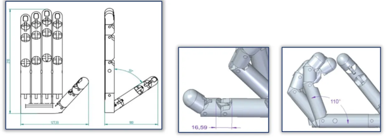
The hand is designed using Solid Edge software. The size of the hand is similar to an average human hand. The size and range of motion is depicted in Figure 3.
Figure 3. The size and range of motion of the hand
Figure 4 shows the whole hand whose every finger is moved by a pneumatic muscle actuator. In this case, only separate movement of fingers is possible.
Figure 4. 3D plan of the hand
ANNALS of Faculty Engineering Hunedoara – International Journal of Engineering Tome XVI [2018] | Fascicule 1 [February]
79 | F a s c i c u l e 1
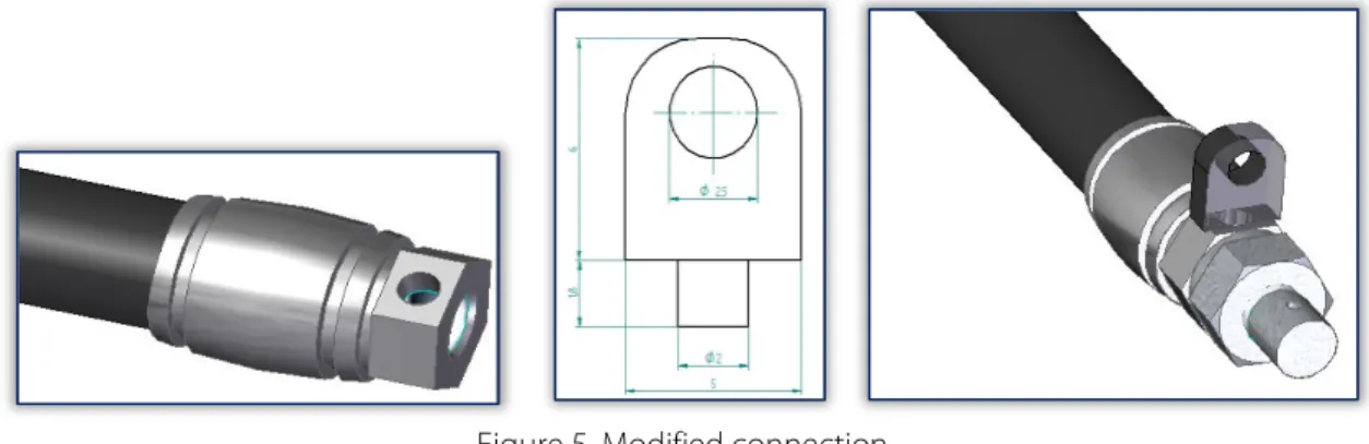
It is necessary to modify the press-fitted connections of PMA for fixing wires. For this reason a simple plug is designed (Figure 5).
Figure 5. Modified connection
A wire is fixed to every pneumatic muscle actuator that moves the finger. For biderictional motion a PMA-rubber system is used: when the PMA is inflated it develops pulling force and if the PMA deflates the rubber pulls back the PMA into initial position. Since every finger is moved separately it is possible to make different gestures with the hand (Figure 6).
Figure 6. Some movements of the hand 3. CONCLUSIONS
The main aim of this work is to prove the following: academic students are capable of designing a human-like hand actuated by pneumatic muscle actuators. This paper presents the DMSP-5 type Fluidic Muscle and with the help of it a hand is planned in Solid Edge environment. To test the hand, 3D printing of it is intended as future work.
References
[1] Daerden F., Lefeber D.: Pneumatic Artificial Muscles: Actuator for Robotics and Automation, European Journal of Mechanical and Environmental Engineering, Vol. 47, 2002, pp. 10-21
[2] Veale A. J., Xie S. Q., Anderson I. A.: Accurate and Versatile Multivariable Arbitrary Piecewise Model Regression of Nonlinear Fluidic Muscle Behavior, IEEE International Conference on Mechatronics (ICM), Churchill, Australia, 13- 15 February, 2017, pp. 254-259
[3] Toman P., Gyeviki J., Endrődy T., Sárosi J., Véha A.: Design and Fabrication of a Test-bed Aimed for Experiment with Pneumatic Artificial Muscle, International Journal of Engineering, Annals of Faculty of Engineering Hunedoara, 2009, Vol. 7, No. 4, pp. 91-94
[4] Sárosi J.: New Approximation Algorithm for the Force of Fluidic Muscles, 7th IEEE International Symposium on Applied Computational Intelligence and Informatics (SACI 2012), Timisoara, Romania, 22-24 May, 2012, pp. 229- [5] 233 Sárosi J., Bíró I., Németh J. Cveticanin L.: Dynamic Modelling of a Pneumatic Muscle Actuator with Two-direction
Motion, Mechanism and Machine Theory, 2015, Vol. 85, pp. 25-34
[6] Sárosi J.: Accurate Positioning of Pneumatic Artificial Muscle at Different Temperatures Using LabVIEW Based Sliding Mode Controller, 9th IEEE International Symposium on Applied Computational Intelligence and Informatics (SACI 2014), Timisoara, Romania, 15-17 May, 2014, pp. 85-89
[7] Sárosi J.: Elimination of the Hysteresis Effect of PAM Actuator: Modelling and Experimental Studies, Technical Gazette, 2015, Vol. 22, No. 6, pp. 1489-1494
[8] Hosovsky A., Pitel J., Zidek K., Tothova M., Sárosi J., Cveticanin L.: Dynamic Characterization and Simulation of Two-link Soft Robot Arm with Pneumatic Muscles, Mechanism and Machine Theory, 2016, Vol. 103, pp. 98-116
ANNALS of Faculty Engineering Hunedoara – International Journal of Engineering Tome XVI [2018] | Fascicule 1 [February]
80 | F a s c i c u l e 1
[9] Csikós S., Balassa Sz., Sárosi J.: Fuzzy Control of an Antagonistic System Driven by Pneumatic Muscle Actuators, 4th International Conference and Workshop Mechatronics in Practice and Education - MECHEDU 2017, Subotica, Serbia, 4-5 May, 2017, pp. 89-92
[10] Sárosi J., Gergely A., Tölgyi F.: Student Project on Pneumatically Driven Muscle-like Actuators, 3rd International Conference and Workshop Mechatronics in Practice and Education - MECHEDU 2015, Subotica, Serbia, 14-15 May, 2015, pp. 153-157
[11] Sárosi J., Csikós S., Szabó Z., Bálint Á., Gergely A., Dobó F.: Pneumatikus mesterséges izom által működtetett rehabilitációs eszközök tervezése és kivitelezése, Jelenkori Társadalmi és Gazdasági Folyamatok, 2015, Vol. 10, No. 2, pp. 131-139
[12] Sárosi J., Gyürky B.: Design and Construction of a Humanoid Arm Driven by Pneumatic Muscle Actuator, Acta Technica Corviniensis, Bulletin of Engineering, 2016, Vol. 9, No. 4, pp. 49-52
[13] Festo: Fluidic muscle DMSP/MAS, 2015, 36 p.
ISSN 1584 - 2665 (printed version); ISSN 2601 - 2332 (online); ISSN-L 1584 - 2665
copyright © University POLITEHNICA Timisoara, Faculty of Engineering Hunedoara, 5, Revolutiei, 331128, Hunedoara, ROMANIA
http://annals.fih.upt.ro
![Figure 1. Student projects related to PMAs [10-12]](https://thumb-eu.123doks.com/thumbv2/9dokorg/1339571.108703/1.892.593.800.600.989/figure-student-projects-related-pmas.webp)