Actuator behaviour modelling in
1
IoT-Fog-Cloud simulation
2
Andras Markus
1, Mate Biro
1, Gabor Kecskemeti
2, and Attila Kertesz
13
1Software Engineering Department, University of Szeged, Szeged, Hungary
4
2Faculty of Engineering and Technology, Liverpool John Moores University, Liverpool,
5
United Kingdom
6
Corresponding author:
7
Andras Markus1
8
Email address: markusa@inf.u-szeged.hu
9
ABSTRACT
10
The inevitable evolution of information technology has led to the creation of IoT-Fog-Cloud systems, which combine the Internet of Things (IoT), Cloud Computing and Fog Computing. IoT systems are composed of possibly up to billions of smart devices, sensors and actuators connected through the Internet, and these components continuously generate large amounts of data. Cloud and fog services assist the data processing and storage needs of IoT devices. The behaviour of these devices can change dynamically (e.g. properties of data generation or device states). We refer to systems allowing behavioural changes in physical position (i.e. geolocation), as the Internet of Mobile Things (IoMT). The investigation and detailed analysis of such complex systems can be fostered by simulation solutions. The currently available, related simulation tools are lacking a generic actuator model including mobility management. In this paper, we present an extension of the DISSECT-CF-Fog simulator to support the analysis of arbitrary actuator events and mobility capabilities of IoT devices in IoT-Fog-Cloud systems. The main contributions of our work are: (i) a generic actuator model and its implementation in DISSECT-CF-Fog, and (ii) the evaluation of its use through logistics and healthcare scenarios. Our results show that we can successfully model IoMT systems and behavioural changes of actuators in IoT-Fog-Cloud systems in general, and analyse their management issues in terms of usage cost and execution time.
11 12 13 14 15 16 17 18 19 20 21 22 23 24 25
1 INTRODUCTION
26
Internet of Things (IoT) is estimated to reach over 75 billion smart devices around the world by 2025
27
(Taylor et al., 2015), which will dramatically increase the network traffic and the amount of data generated
28
by them. IoT systems often rely on Cloud Computing solutions, because of its ubiquitous and theoretically
29
infinite, elastic computing and storage resources. Fog Computing is derived from Cloud Computing to
30
resolve the problems of increased latency, high density of smart devices and the overloaded communication
31
channels, which also known as the bottleneck-effect.
32
Real-time IoT applications (Ranjan et al., 2020) require faster and more reliable data storage and
33
processing than general ones, especially when data privacy is also a concern. The proximity of Fog
34
Computing nodes to end users usually ensures short latency values, however these nodes are resource-
35
constrained as well. Fog Computing can aid cloud nodes by introducing additional layers between the
36
cloud and the IoT devices, where a certain part of the generated data can be processed faster (Mahmud
37
et al., 2018).
38
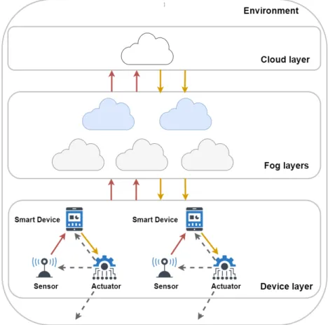
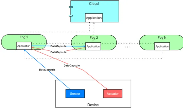
A typical fog topology is shown in Figure 1, where sensors and actuators of IoT devices are located at
39
the lowest layer. Based on their configuration and type, things produce raw sensor data. These are then
40
stored and processed on cloud and fog nodes (this data flow is denoted by red dotted arrows). Sensors are
41
mostly resource-constrained and passive entities with restricted network connection, on the other hand,
42
actuators ensure broad functionality with Internet connection and enhanced resource capacity (Ngai et al.,
43
2006).
44
They aspire to make various types of decisions by assessing the processed data retrieved from the
45
nodes. This data retrieval is marked by solid orange arrows in Figure 1. These actions can affect on the
46
physical environment or refine the configuration of the sensors, such modification can be the increasing or
47
decreasing of the data sampling period or extending the sampling period, this later results in different
48
amounts of generated data. Furthermore, the embedded actuators can manipulate the behaviour of smart
49
devices, for instance, restart or shutdown a device, and motion-related responses can also be expected.
50
These kind of actions are noted by grey dashed arrows in Figure 1.
51
Figure 1.The connections and layers of a typical fog topology
In the surrounding world of IoT devices, location is often fixed, however, the Quality of Service
52
(QoS) of these systems should also be provided at the same level in case of dynamic and moving devices.
53
Systems composed of IoT devices supporting mobility features are also known as the Internet of Mobile
54
Things (IoMT) (Nahrstedt et al., 2020). Mobility can have a negative effect on the QoS to be ensured
55
by fog systems, for instance, they could increase the delay between the device and the actual node it is
56
connected to. Furthermore, using purely cloud services can limit the support for mobility (Pisani et al.,
57
2020).
58
Wireless Sensor Networks (WSN) are considered as predecessors of the Internet of Things. In
59
a WSN, the naming convention of sensor and actuator components follows publisher/subscriber or
60
producer/consumer notions (Sheltami et al., 2016), however IoT sensor and actuator appellations are
61
commonly accepted by the IoT simulation community as well. Publishers (i.e. sensors or producers) share
62
the data which are sensed in the environment, until then subscribers (i.e. actuators or consumers) react to
63
the sensor data (or to an incoming message) with an appropriate action. In certain situations, actuators
64
can have both of these roles, and behave as a publisher, especially when the result of a command executed
65
by an actuator needs to be sent and further processed.
66
Investigating IoT-Fog-Cloud topologies and systems in real word is rarely feasible on the necessary
67
scales, thus different simulation environments are utilised by researchers and system architects for such
68
purpose. It can be observed that only a few of the currently available simulation tools deal with a minimal
69
ability to model actuator and/or mobility events, which strongly restricts their usability. It implies that
70
a comprehensive simulation solution, with an extendable, well-detailed mobility and actuator model, is
71
missing for fog-enhanced IoT systems.
72
To address this open issue, we propose a generic actuator model for IoT-Fog-Cloud simulators and
73
implement it by extending the DISSECT-CF-Fog (Markus et al., 2020) open-source simulator, to be
74
able to model actuator components and mobility behaviour of IoT devices. As the main contributions
75
of our work, our proposal enables: (i) more realistic and dynamic IoT behaviour modelling, which
76
can be configured by using the actuator interface of IoT devices, (ii) the ability of representing and
77
managing IoT device movement (IoMT), and (iii) the analysis of different types of IoT applications having
78
actuator components in IoT-Fog-Cloud environments. Finally, the modelling of such complex systems are
79
demonstrated through a logistics and a healthcare scenario.
80
The rest of the paper is structured as follows: Section 2 introduces and compares the related works,
81
Section 3 presents our proposed actuator model and simulator extension. Section 4 presents our evaluation
82
scenarios, and finally Section 5 concludes our work.
83
2 RELATED WORK
84
According to the definition by (Bonomi et al., 2012), an actuator is a less limited entity than a sensor in
85
terms of its network connectivity and computation power, since it is responsible for controlling or taking
86
actions in an IoT environment. Usually actuators are identified as linear, motors, relays or solenoids to
87
induce motion of a corresponding entity. The work in Motlagh et al. (2020) categorises actuators based
88
on their energy source as following: (i) pneumatic, (ii) hydraulic, (iii) electric and finally (iv) thermal
89
actuator, however this kind of classification might restrict the usability of actuators to the energy sector.
90
The presence of actuators plays a vital role in higher level software tools for IoT as well, for instance
91
in FogFlow (Cheng et al., 2018). It is an execution framework dedicated for service orchestrations over
92
cloud and fog systems. This tool helps infrastructure operators to handle dynamic workloads of real IoT
93
services enabling low latency on distributed resources. According to their definition, actuators perform
94
actions (e.g. turning on/off the light) in an IoT environment, which can be coordinated by an external
95
application.
96
The already existing, realised actuator solutions are well-known and commonly used in Technical
97
Informatics, however the modelling of an actuator entity in simulation environments is not straightforward,
98
and most of the simulation tools simply omit or simplify it, nevertheless actuators are considered as
99
essential components of the IoT world.
100
Concerning IoT and fog simulation, a survey paper by Svorobej et al. (2019) compares seven simulation
101
tools supporting infrastructure and network modelling, mobility, scalability, resource and application
102
management. Unfortunately, in some cases the comparison is restricted to a binary decision, for instance
103
if the simulator has a mobility component or not. Another survey by Markus and Kertesz (2020) examined
104
44 IoT-Fog-Cloud simulators, in order to determine the characteristics of these tools. 11 parameters were
105
used for the comparison, such as type of the simulator, the core simulator, publication date, architecture,
106
sensor, cost, energy and network model, geolocation, VM management and lastly, source code metrics.
107
These survey papers represent the starting point for our further investigations in the direction of geolocation
108
and actuator modelling.
109
FogTorchPI (Brogi et al., 2018) is a widely used simulator, which focuses on application deployment in
110
fog systems, but it limits the possibilities of actuator interactions. Tychalas and Karatza (2018) proposed a
111
simulation approach focusing on the cooperation of smartphones and fog, however the actuator component
112
was not considered for the evaluation.
113
The CloudSim-based iFogSim simulator (Gupta et al., 2016) is one of the leading fog simulators
114
within the research community, which follows the sense-process-actuate model. The actuator is declared
115
as the responsible entity for the system or a mechanism, and the actualisation event is triggered when a
116
task, which known as a Tuple, determining a certain amount of instruction and size in bytes, is received
117
by the actuator. In the current implementation of iFogSim, this action has no significant effect, however
118
custom events also can be defined by overriding the corresponding method, nevertheless no such events
119
are created by default. The actuator component is determined by its connection and network latency. The
120
original version of iFogSim does not support mobility, however the static, geographical location of a node
121
is stored.
122
Another CloudSim extension is the EdgeCloudSim (Sonmez et al., 2018), which aims to ensure
123
mobility support in simulation environments. It associates the position information of a mobile device to a
124
two-dimensional coordinate point, which can be updated dynamically. This simulation solution considers
125
the nomadic mobility model, by its definition, a group of nodes moves randomly from one position to
126
another. This work also takes into account the attractiveness of a position to define the duration of stay at
127
some place. Further mobility models can be created by extending the default class for mobility, but there
128
is no actuator entity implemented in this approach.
129
The FogNetSim++ (Qayyum et al., 2018) can be used to model fog networks supporting heterogeneous
130
devices, resource scheduling and mobility. In this paper six mobility strategies were proposed, and new
131
mobility policies can also be added. This simulator aids the entity mobility models, which handles
132
the nodes independently, and takes into account parameters such as speed, acceleration, direction in a
133
three-dimensional coordinate system. Unfortunately, the source code of the simulator presents examples
134
of the linear and circular mobility behaviour only. This simulation tool used no actuator model.
135
YAFS (Lera et al., 2019) is a simulator to analyse IoT application deployments and mobile IoT
136
scenarios. The actuator in this realisation is defined as an entity, which receives messages with the given
137
number of instructions and bytes, similarly to the solution of iFogSim. The paper also mentioned dynamic
138
user mobility, which takes into account different routes using GPX formats (it is used by application to
139
depict data on the map), but this behaviour was not explained or experimented with.
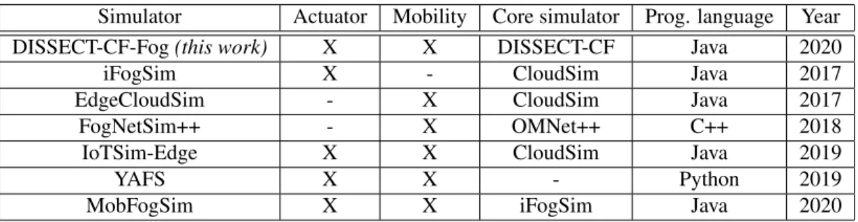
Simulator Actuator Mobility Core simulator Prog. language Year
DISSECT-CF-Fog(this work) X X DISSECT-CF Java 2020
iFogSim X - CloudSim Java 2017
EdgeCloudSim - X CloudSim Java 2017
FogNetSim++ - X OMNet++ C++ 2018
IoTSim-Edge X X CloudSim Java 2019
YAFS X X - Python 2019
MobFogSim X X iFogSim Java 2020
Table 1. Comparison of the related simulation tools
140
Jha et al. (2020) proposed the IoTSim-Edge simulation framework by extending the CloudSim to
141
model towards IoT and Edge systems. This simulator focuses on resource provisioning for IoT applications
142
considering the mobility function and battery-usage of IoT devices, and different communication and
143
messaging protocols as well. The IoTSim-Edge contains no dedicated class for the actuator components,
144
nevertheless the representative class of an IoT device has a method for actuator events, which can be also
145
overridden. There is only one predefined actuator event affecting the battery of an IoT device, however
146
it was not considered during the evaluation phase by the authors. This simulation tool also takes into
147
consideration the mobility of smart devices. The location of a device is represented by a three-dimensional
148
coordinate system. Motion is influenced by a given velocity and range, where the corresponding device
149
can move, and only horizontal movements are considered within the range by the default moving policy.
150
MobFogSim (Puliafito et al., 2020) aims to model user mobility and service migration, and it is one of
151
the latest extension of the iFogSim, where actuators are supported by default. Furthermore, the actuator
152
model was revised and improved to handle migration decisions, because migration is often affected by
153
end user motions. To represent mobility, it uses a two-dimensional coordinate system, the users’ direction
154
and velocity. The authors considered real datasets as mobility patterns, which describe buses and routes
155
of public transportation.
156
The comparison of related simulation based approaches is shown in Table 1. It highlights the existence
157
of actuator and mobility interfaces, the base simulator of the approach and the programming language, in
158
which the actual tool was written. We also denoted the year, when the simulation solution was released or
159
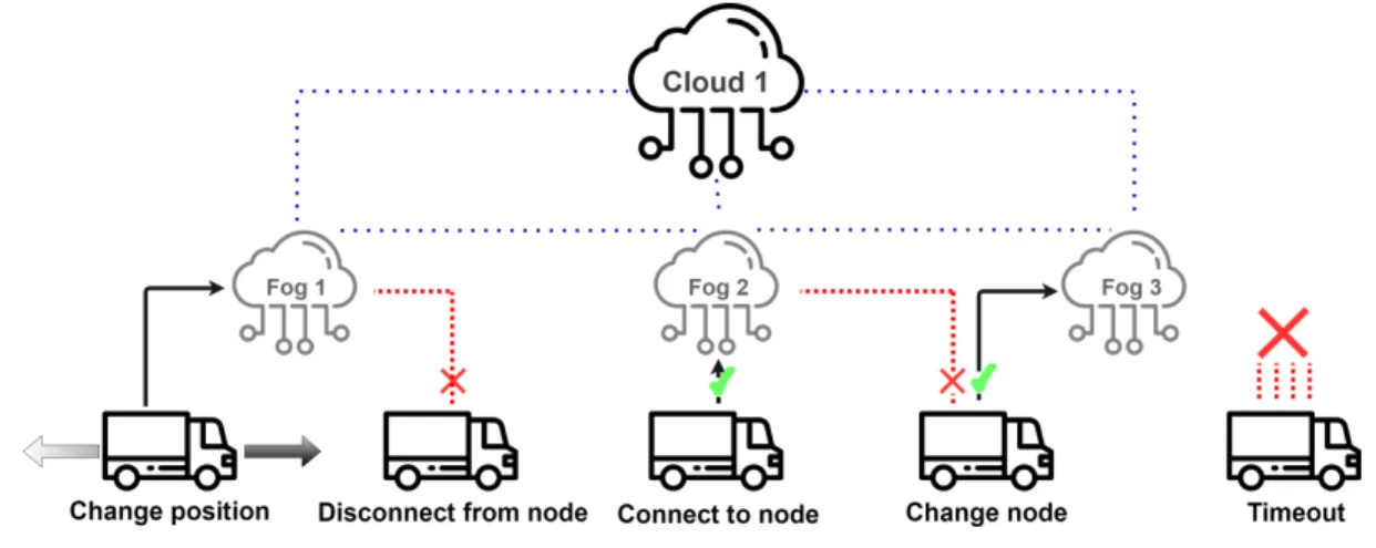
published. It also reveals the leading trends for fog simulation. Based on Markus and Kertesz (2020),
160
more than 70% of the simulators are written in Java programming language and only 20% of them are
161
developed using Python or C++. The rest of them are more complex applications (i.e. Android-based
162
software). This survey also points out that mostly the network type of simulators is written in C++, which
163
focuses on fine-grained network model, however these tools typically do not have predefined models and
164
components for representing cloud and fog nodes, and VM management operations. The event-driven
165
general purpose simulators are usually implemented in Java.
166
The actuator and mobility abilities of these simulators are further detailed in Table 2. The second
167
column shows possible directions for transferring the sensor data (usually in the form of messages), in
168
case the actuator interface is realised in the corresponding simulator. It can be observed that it basically
169
Simulator Communication direction Actuator events Mobility Position DISSECT-CF-Fog
(this work)
- Sensor→Fog / Cloud→Actuator - Sensor→Actuator
- 10 different predefined actions for actuation - Adding new by overriding
- Nomadic - Random Walk
Latitude, Longitude iFogSim - Sensor→Fog→Actuator - Default, but it can be
overridden - Coordinates
EdgeCloudSim - - - Nomadic Coordinates
FogNetSim++ - - - Linear
- Circular Coordinates IoTSim-Edge - Sensor→Fog Device→Actuator - Default, but it can be
overridden - Linear Coordinates
YAFS - Sensor→Service→Actuator - - Real dataset Latitude,
Longitude MobFogSim - Mobile Sensor→Mobile Device
→- Mobile Actuator - Migration - Linear
- Real dataset Coordinates Table 2.Detailed characteristics of the related simulation tools
follows similar logic in all cases. The third column highlights actuator events that can be triggered in a
170
simulator. The fourth column shows the supported mobility options (we only listed the ones offered in
171
their source code) and finally we denoted the position representation manner in the last column.
172
One can observe that there is a significant connection between mobility support and actuator functions,
173
but only half of the investigated simulators applied both of them. Since the actuator has no commonly used
174
software model within the latest simulation tools, developers omit it, or it is left to the users to implement
175
it, which can be time consuming (considering the need for additional validation). In a few cases, both
176
actuator and mobility models are simplified or just rudimentary handled, thus realistic simulations cannot
177
be performed.
178
In this paper, we introduce an actuator interface and mobility functionality for the DISSECT-CF-Fog
179
simulator. We define numerous actuator events and mobility patterns to enhance and refine the actuator
180
model of a simulated IoT system. To the best of our knowledge, no other simulation solution offers such
181
enriched ways to model actuator components.
182
3 THE ACTUATOR AND MOBILITY MODELS OF DISSECT-CF-FOG
183
The heterogeneity of interconnected IoT devices often raises difficulties in simulator solutions, as the
184
creation of a model that comprehensively depicts the behaviour of these diverse components is challenging.
185
In a simulation environment, a concrete type of any device is described by its characteristics. For instance,
186
it does not really matter, if a physical machine utilises an AMD or an Intel processor, because the
187
behaviour of the processor are modelled by the number of CPU cores and the processing power of one
188
core, which should be defined in a realistic way. Following this logic, the actual realisation of an actuator
189
entity – which follows the traditional subscriber model –, can be any type of actuator (e.g. motors or
190
relays), if the effects of it are appropriately and realistically modelled. This means that in our actuator
191
implementation, a command received by an actuator must affect the network load considering bandwidth
192
and latency, moreover based on certain decisions the actuator should indicate changes in the behaviour of
193
the IoT device or sensor (e.g. increasing data sensing frequency or changing the actual position). In case
194
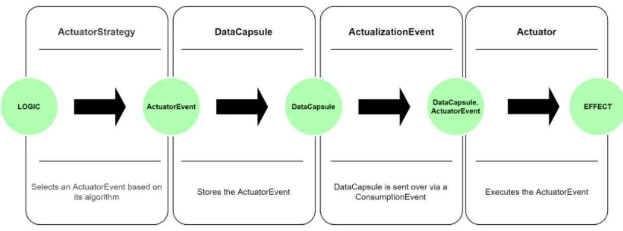
of IoMT, the traditional WSN model cannot be followed, hence moving devices can act as a publisher
195
(monitoring) and subscriber as well (receiving commands related to movements).
196
Our proposed actuator interface of the DISSECT-CF-Fog simulator aims to provide a generic, unified,
197
compact and platform-independent representation of IoT actuator components. DISSECT-CF-Fog is based
198
on DISSECT-CF (Kecskemeti, 2015), which was proposed as a general purpose simulator to investigate
199
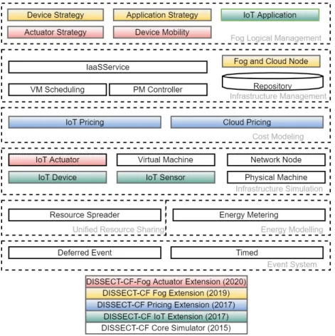
the energy consumption of cloud infrastructures. The evolution phases of DISSECT-CF-Fog can be seen
200
in Figure 2, where each background colour represents a milestone of the development, and it also depicts
201
the layers of the simulation tool.
202
Typical event-driven simulators are lacking predefined models for complex behaviours (e.g. con-
203
sidering both detailed network and computational resource utilisation), nevertheless DISSECT-CF has
204
such abilities. It utilises its own discrete event simulation (DES) engine, which is responsible to manage
205
the time-dependent entities (Event System) and also considers low-level computing resource sharing,
206
for instance balancing network bandwidth (Unified Resource Sharing) or enabling the measurement of
207
different energy usage patterns of resources (Energy Modelling). Through theInfrastructure Simulation
208
andInfrastructure Managementlayers, general IaaS clouds can be modelled with different scheduling
209
policies.
210
The current version of DISSECT-CF-Fog strongly build on the subsystems of the basic simulator,
211
which is proven to be accurate. This system has been leveraged since 2017 to realise different aspects of
212
complex IoT-Fog-Cloud systems. First, we added the typical components of IoT systems (denoted by
213
green in Figure 2) likeIoT Sensor,IoT DeviceandIoT Application, to model various IoT use cases with
214
detailed configuration options. The naming DISSECT-CF-Fog was introduced at the end of 2019, after
215
developing theCost Modellinglayer to apply arbitrary IoT and cloud side cost schemes of any providers
216
(shown by blue coloured boxes in Figure 2). The tree main components of the fog extension, denoted
217
by yellow (Figure 2), are theFog and Cloud Node, which are responsible for the creation of multi-tier
218
fog topology, theDevice Strategy, which chooses the optimal node for a device, and (iii) theApplication
219
Strategy, which enables offloading decisions between the entities of the fog topology. The strategies can
220
take into account various parameters of the system, such as network properties (e.g. latency), cost and
221
utilised CPU and memory.
222
The main contribution of this paper are denoted by red in Figure 2. To satisfy the increasing need for
223
a well-detailed and versatile simulator, we complete the IoT layer by adding theIoT Actuatorcomponent,
224
with its corresponding management elementsActuator StrategyandDevice Mobility, to realise the business
225
logic for such related behaviours. In the former versions of DISSECT-CF-Fog, the position of IoT devices
226
were static and fixed, and also the backward communication channels (from the computational nodes to
227
actuators through the IoT devices) did not exist.
228
Figure 2. The evolution of DISSECT-CF-Fog through its components
3.1 Actuator Model
229
In the layered architecture of IoT, actuators are located in the perception layer, which is often referred to
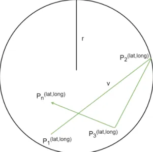
230
as the lowest or physical layer that requires the most detailed level of abstraction in IoT.
231
In this paper, we are focusing mainly on software-based actuator solutions due to their increasing
232
prevalence in the field of IoT. The DISSECT-CF-Fog actuator model is fairly abstract, hence it mainly
233
focuses on the actuators’ core functionality and its effect on the simulation results, but it does not go deep
234
into specific actuator-device attributes.
235
The actuator interface should facilitate a more dynamic device layer and a volatile environment in
236
a simulation. Therefore, it is preferred to be able to implement actuator components in any kind of
237
simulation scenario, if needed. In our model, one actuator is connected to one IoT device for two reasons
238
in particular: (i) it is observing the environment of the smart device and can act based on previously
239
specified conditions, or (ii) it can influence some low-level sensor behaviour, for instance it changes the
240
sampling interval of a sensor, resets or completely stops the smart device.
241
The latter indirectly conveys the conception of a reinterpreted actuator functionality for simulator
242
solutions. The DISSECT-CF-Fog actuator can also behave as a low-level software component for sensor
243
devices, which makes the model compound.
244
The actuator model of DISSECT-CF-Fog can only operate with compact, well-defined events, that
245
specify the exact influence on the environment or the sensor. The set of predefined events during a
246
simulation provides a restriction to the capability of the actuator and limits its scope to certain actions that
247
are created by the user or already exist in the simulator. A brief illustration of sensor-based events are
248
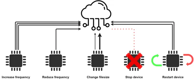
shown in Figure 3.
249
Figure 3. Low-level sensor events
The determination of the exact event, executed by the actuator, happens in a separate, reusable and
250
extendable logic component. This logic component can serve as an actual actuator configuration, but can
251
also be used as a descriptor for environmental changes and their relations to specific actuator events. This
252
characteristic makes the actuator interface thoroughly flexible and adds some more realistic factors to
253
certain simulation scenarios.
254
With the help of the logic component, the actuator interface works in an automatic manner. After a
255
cloud or fog node has processed the data generated by the sensors, it sends a response message back to
256
the actuator, which chooses an action to be executed. This models the typical sensor-service-actuator
257
communication direction.
258
Unexpected actions may occur in real-life environments, which are hard to be defined by algorithms,
259
and the execution of some events may not require cloud or fog processes, e.g. when a sensor fails. To be
260
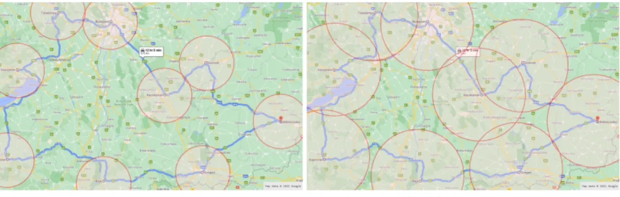
able to handle such issues, the actuator component is capable of executing events apart from its predefined
261
configuration. This feature facilitates the immediate and direct communication between sensors and
262
actuators.
263
For the proper behaviour of the actuator, the data representation in the simulator needs to be more
264
detailed and comprehensive. Consequently, this extension of the DISSECT-CF-Fog simulator introduces
265
a new type of data fragment in the system, to store specific details throughout the life-cycle of the
266
sensor-generated data.
267
Finally, the DISSECT-CF-Fog actuator should be optional for simulation scenarios. In consideration
268
of certain scenarios, where the examined results do not depend on the existence of actuator behaviours,
269
the simulation can be run without the actuator component. This might significantly decrease the actual
270
runtime of the simulation, as there could potentially be some computing heavy side effects, when applying
271
actuator functionalities.
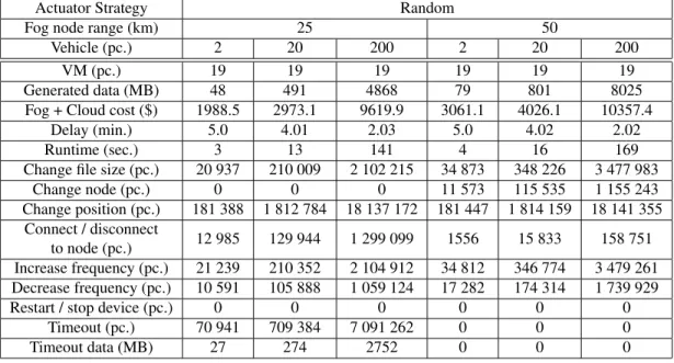
272
3.2 Requirements for modelling the Internet of Mobile Things
273
The proximity of computing nodes is the main principle of Fog Computing and it has numerous benefits,
274
but mobile IoT devices may violate this criterion. These devices can move further away from their
275
processing units, causing higher and unpredictable latency. When a mobile device moves out of range of
276
the currently connected fog node, a new, suitable fog node must be provided. Otherwise, the quality of
277
service would drastically deteriorate and due to the increased latencies, the fog and cloud nodes would
278
hardly be distinguishable in this regard, resulting in losing the benefits of Fog Computing.
279
Another possible problem that comes with mobile devices is service migration. The service migration
280
problem can be considered as when, where and how (W2H) questions. Service migration usually happens
281
between two computing nodes, but if there is no fog node in an acceptable range, the service could be
282
migrated to the smart device itself, causing lower performance and shorter battery time. However, service
283
migration only makes sense when there are stateful services, furthermore it is beyond the topic of this
284
paper, we consider stateless services and decisions of their transfer among the nodes only.
285
The physical location of fog nodes in a mobile environment is a major concern. Placing Fog Computing
286
nodes too far from each other will result in higher latency or connection problems. In this case, IoT
287
devices are unable to forward their data, hence they are never processed. Some devices may store their
288
data temporarily, until they connect to a fog node, but this contradicts real-time data processing promises
289
of fogs.
290
A slightly better approach would be to install fog nodes fairly dense in space to avoid the problem
291
discussed above. However, there might be some unnecessary nodes in the system, causing a surplus in the
292
infrastructure, which results in resource wastage.
293
Considering different mobility models for mobile networks in simulation environments have been
294
researched for a while. The survey by Camp et al. (2002) presents 7 entity and 6 group mobility models
295
in order to replace trace files, which can be considered as the footprints of movements in the real world.
296
Applying mobility models is a reasonable decision, because they mimic the movements of IoT devices in
297
a realistic way. The advent of IoT and the technological revolution of smartphones have brought the need
298
for seamless and real time services, which may require an appropriate simulation tool to develop and test
299
the cooperation of Fog Computing and moving mobile devices.
300
The current extension of the DISSECT-CF-Fog was designed to create a precise geographical position
301
representation of computing nodes (fog, cloud) and mobile devices and simulate the movements of devices
302
based on specified mobility policies. As the continuous movement of these devices could cause connection
303
problems we consider the following events shown in Figure 4.
304
Figure 4.Actuator events related to mobility behaviour
Examining the occurrence of these specific events can help in optimising the physical allocation of
305
fog nodes depending on the mobility features of IoT devices.
306
3.3 Actuator implementation in DISSECT-CF-Fog
307
DISSECT-CF-Fog is a discrete event simulator, which means there are dedicated moments, when system
308
variables can be accessible and modifiable. The extended classes of the timing events, which can be
309
recurring and deferred, ensure to create the dedicated time-dependent entities in the system.
310
As mentioned in Section 3.1, a complex, detailed data representation in the simulator is mandatory
311
in order to provide sufficient information for the actuator component. Data fragments are represented
312
byDataCapsuleobjects in the system of DISSECT-CF-Fog. The sensor-generated data is wrapped in a
313
well-parameterizedDataCapsuleobject, and forwarded to an IoTApplicationlocated in a fog or cloud
314
node to be processed. ADataCapsuleobject uses the following attributes:
315
• source: Holds a reference to the IoT device generating sensor data, so the system keeps track of the
316
data source.
317
• destination: Holds a reference to theApplicationof a fog node where the data has been originally
318
forwarded to.
319
• dataFlowPath: In some cases fog nodes cannot process the current data fragment, therefore they
320
might send it to another one. This parameter keeps track of the visited fog nodes by the data before
321
it has been processed.
322
• bulkStorageObject: Contains one or more sensor-generated data that has been wrapped into one
323
DataCapsule.
324
• evenSize: The size of the response message sent from a fog node to the actuator component (in
325
bytes). This helps to simulate network usage while sending information back to the actuator.
326
• actuationNeeded: Not every message from the IoT device requires an actuator response event. This
327
logical value (true - false) holds true, if the actuator should take action after the data has been
328
processed, otherwise it is false.
329
• fogProcess: A logical value (true - false), that is true, if the data must be processed in a fog node,
330
and should not be sent to the cloud. It is generally set to true, when real-time response is needed
331
from the fog node.
332
• startTime: The exact time in the simulator, when the data was generated.
333
• processTime: The exact time in the simulator, when the data was processed.
334
• endTime: The exact time in the simulator, when the response has been received by the actuator.
335
• maxToleratedDelayandpriorityLevel: These two attributes define the maximum delay tolerated by
336
the smart device and the priority of the data. Both of them could play a major role in task-scheduling
337
algorithms (e.g., priority task scheduling), but they have no significant role in the current extension.
338
• actuatorEvent: This is the specific event type that is sent back to the actuator for execution.
339
To set these values accurately, some sensor-specific and environment-specific properties are required.
340
TheSensorCharacteristicsclass integrates these properties and helps to create more realistic simulations.
341
The following attributes can be set:
342
• sensorNum: The number of applied sensors in a device. It is directly proportional to the size of the
343
generated data.
344
• mttf: The mean time until the sensor fails. This attribute is essential to calculate the sensor’s average
345
life expectancy, which helps in modelling sensor failure events. If the simulation’s time exceeds the
346
mttf value, the sensor has a higher chance to fail. If a sensor fails, the actuator forces it to stop.
347
• minFreqandmaxFreq: These two numbers represent the maximum and minimum sampling rate of
348
the sensor. If a sensor does not have a predefined sampling rate but rather senses changes in the
349
environment, then these are environment-specific attributes and their values could be defined by
350
estimating the minimum and maximum time interval between state changes in the environment.
351
These attributes are necessary to limit the possible frequency value of a sensor when the actuator
352
imposes an event which affects the frequency.
353
• fogDataRatio: An estimation on how often the sensor generates data, that requires a fog process.
354
This value is usually higher in the case of sensors that generate sensitive data or applications that
355
require real-time response.
356
• actuatorRatio: An estimation on how often the sensor generates data, that requires actuator
357
action. This is typically an environment-specific attribute. The more inconsistent and variable the
358
environment is, the higher its chance to trigger the actuator, thus the value of this attribute should
359
be set higher. This attribute has an impact on theDataCapsule’sactuationNeededvalue. If the
360
actuatorRatiois higher, then it is more likely to set theactuationNeededattribute to true.
361
• maxLatency: Its value determines the maximum latency tolerated by the device when communi-
362
cating with a computing node. For instance, in the case of medical devices, this value is generally
363
lower than in the case of agricultural sensors. Mobile devices may move away from fog nodes
364
inducing latency fluctuations and this attribute helps to determine whether a computing node is
365
suitable for the device, or the expected latency exceeds thismaxLatencylimitation, therefore the
366
device should look for a new computing node. This attribute plays a major role in triggering
367
fog-selection actuator events when the IoT device is moving between fog nodes.
368
• delay: The delay of the data generating mechanism of the sensor.
369
Figure 5. Data flow in the DISSECT-CF-Fog
When creating an IoT device in the simulation, itsSensorCharacteristicsfeatures should also be
370
defined. This will enable the simulated device to start generatingDataCapsuleobjects according to
371
its characteristics. This is the start of the life-cycle of aDataCapsuleobject.DataCapsuleobjects are
372
forwarded to a certainApplicationof a fog node, based on the fog selection strategy of the device.
373
The corresponding timed method (called(tick())) of theApplicationis responsible for processing
374
the data on a fog node. If the actual fog node has adequate resources to process the received data, the
375
processing happens, and if theactuationNeededattribute of the processedDataCapsuleobject was true,
376
then it is sent back to the actuator (i.e., the data source) expanded with a specificactuatorEventobject
377
(denoting an action to be performed by the actuator). After the data object stored in theDataCapsuleis
378
received by the actuator, it executes the event. If theactuationNeededattribute was false during the data
379
processing, then the procedure mentioned before is omitted. Otherwise, if the current fog node does not
380
have the capacity to process the data, it sends them over to another node based on the actual strategy of
381
theApplication.
382
The life-cycle of aDataCapsule object ends, when the actuator interface receives a notification
383
indirectly by triggering a consumption event for which the IoT device has been subscribed to.By definition
384
of theDataCapsule, its life-cycle can also end without actualisation events, if theactuationNeededis set
385
to false. A simplified demonstration of theDataCapsule’s path in the system (meaning the data flow) can
386
be seen in Figure 5.
387
The actuator model in DISSECT-CF-Fog is represented as the composition of three entities that highly
388
depend on each other. These entities are theActuator,ActuatorStrategyand theActuatorEvent. The
389
entities are serving input directly or indirectly for each other, as shown in Figure 6.
390
Figure 6.Operation of the actuator model
As mentioned in Section 3.1 the actuator model must only operate with predefined events to limit its
391
scope to certain actions. These events are represented by theActuatorEventcomponent, which is the
392
core element of this model. By itself, theActuatorEventis only an interface and should be implemented
393
in order to specify an exact action. There are some predefined events in the system: five of them are
394
low-level, sensor-related events (as discussed in Section 3.1, the other five are related to the mobile
395
functionality of the devices, but these can be extended to different types of behaviours.
396
Since the actuator has the ability to control the sensing process itself (Pisani et al., 2020), half of the
397
predefined actuator events foster low-level sensor interactions. TheChange filesizeevent can modify
398
the size of the data to be generated by the sensor. Such behaviour reflects use cases, when more or
399
less detailed data are required for the corresponding IoT application, or the data should be encrypted or
400
compressed for some reason. TheIncrease frequencyandDecrease frequencymight be useful when the
401
IoT application requires an increased time interval between the measurements of a sensor. A typical use
402
case of this behaviour is when a smart traffic control system of a smart city monitors the traffic at night,
403
when usually less inhabitants are located outside. The maximum value of the frequency is regulated by
404
the correspondingSensorCharacteristicsobject. TheDecrease frequencyis the opposite of the previously
405
mentioned one, a typical procedure may appear in IoT healthcare, for instance the blood pressure sensor
406
of a patient measures continuously increasing values, thus more frequent perceptions are required. The
407
minimum value of the frequency is regulated by the correspondingSensorCharacteristics. TheStop
408
deviceevent imposes fatal error of a device, typically occurring randomly, and it is strongly related to the
409
mttfof theSensorCharacteristics. Themttf is considered as a threshold, before reaching it, there is only a
410
small chance for failure, after exceeding it, the chance of a failure increases exponentially. Finally, the
411
Restart devicereboots the given device to simulate software errors or updates.
412
Customised events can be added to the simulation by defining theactuate()method of theActu-
413
atorEventclass, that describes the series of actions to occur upon executing the event. The event is
414
selected corresponding to theActuatorStrategy, which is a separate and reusable logic component and
415
indispensable according to Section 3.1. It is also an interface, and should be implemented to define
416
scenario-specific behaviour. Despite its name, theActuatorStrategyis capable of more than just simulating
417
the configuration of an actuator and its event selection mechanism. This logic component can also be
418
used to model the environmental changes and their side effects.
419
DISSECT-CF-Fog is a general fog simulator that is capable of simulating a broad spectrum of scenarios
420
only by defining the key features and functionalities of each element of a fog and cloud infrastructure.
421
TheActuatorStrategymakes it possible to represent an environment around an IoT device, and make
422
the actuator component reactive to its changes. For instance, let us consider a humidity sensor and a
423
possible implementation of the actuator component. We can then mimic an agricultural environment in the
424
ActuatorStrategywith the help of some well-defined conditions to react to changes in humidity values, and
425
select the appropriate customised actuator events (e.g. opening windows, or watering), accordingly. This
426
characteristic enables DISSECT-CF-Fog to simulate environment-specific scenarios, while maintaining
427
its extensive and generic feature.
428
Finally, theActuatorcomponent executes the implemented actions and events. There are two possible
429
event executions offered by this object:
430
1. It can execute an event selected by the strategy. This is the typical usage, and it is performed
431
automatically for devices needing actualisation, every time after the data have been processed by a
432
computing unit, and a notification is sent back to the device.
433
2. Single events can also be fired by the actuator itself. If there is no need for an intermediate
434
computing unit (i.e. data processing and reaction for the result), the actuator can act immediately,
435
wherever it is needed as we mentioned in Section 3.1.
436
There might be a delay between receiving anActuatorEventand actually executing it, especially when
437
the execution of the event is a time consuming procedure. This possible delay can be set by thelatency
438
attribute of theActuator. By default, a device has no inherent actuator component, but it can be explicitly
439
set by thesetActuator()method in order to fulfil the optional presence of the actuator as mentioned in
440
Section 3.1.
441
3.4 Representing IoMT environments in DISSECT-CF-Fog
442
The basis of mobility implementations in the competing tools usually represent the position of users
443
or devices as two or three-dimensional coordinate points, and the distance between any two points
444
is calculated by the Euclidean distance, whereby the results can be slightly inaccurate. To overcome
445
this issue and have a precise model ( as we stated in Section 3.2, we take into account the physical
446
position of the end users, IoT devices and data centres (fog, cloud) by longitude and latitude values. The
447
representative class calledGeoLocationcalculates distance using the Haversine formula. Furthermore,
448
applying geographical location with a coordinate system often results in a restricted map, where the
449
entities are able to move, thus in our case worldwide use cases can be implemented and modelled.
450
Figure 7.Random Walk mobility model
In real life, the motion of an entity can be represented by a continuous function, however in DISSECT-
451
CF-Fog the discrete events reflect the state of the function describing a motion, thus continuous movements
452
are transformed into such events, for instance modifying the direction in discrete moments. Therefore, the
453
actual position only matters and is evaluated before the decisions are made by a computing appliance or a
454
device, for instance when the sensed data is ready to be forwarded.
455
As we stated in Section 3.2, the mobile device movements are based on certain strategies. Currently
456
two mobility strategies are implemented. We decided to implement one entity and one group mobility
457
model according to Camp et al. (2002), but since we provide a mobility interface, the collection of the
458
usable mobility models can be easily extended.
459
The goal of the (i)Nomadicmobility model is that entities move together from one location to another, in our realisation multiple locations (i.e. targets) are available. It is very similar to the public transport of a city, where the route can be described by predefined points (or bus stops), and the dedicated points (Pi) are defined as entities of theGeoLocationclass. An entity reaching the final point of the route will no longer move, but may function afterwards. Between the locations, a constantvspeed is considered, and there is a fixed order of the stops as follows:
P1(lat,long)→v P2(lat,long)→v ...→v Pn(lat,long)
The (ii)Random Walkmobility takes into consideration entities with unexpected and unforeseen
460
movements, for instance the observed entity walks around the city, unpredictably. The aim of this policy
461
is to avoid moving in straight lines with a constant speed during the simulation, because such movements
462
are unrealistic. In this policy, a range of the entity is fixed (r), where it can move with a random speed
463
(v). From time to time, or if the entity reaches the border of the range, the direction and the speed of the
464
movement dynamically change (Pi). That kind of movement is illustrated in Figure 7.
465
TheMobilityDecisionMakerclass is responsible for monitoring the position of the fog nodes and
466
IoT devices, and making decisions knowing these properties. This class has two main methods. The
467
(i)handleDisconnectFromNode()closes the connection with the corresponding node in case the latency
468
exceeds the maximum tolerable limit of the device, or the IoT device is located outside of the range of the
469
node. The (ii) handleConnectToNode()method is used, when a device finds a better fog node instead
470
of the current one, or the IoT device runs without connection to any node, and it finds an appropriate
471
one. These methods are directly using the actuator interface to execute the corresponding mobility-based
472
actuator events.
473
As we mentioned earlier, actuation and mobility are interlinked, thus we introduce five actuator events
474
related to mobility according to Section 3.2. Position changes are done byChange positionevent of the
475
actuator. The connection or disconnection methods of a device are handled by theDisconnect from node
476
andConnect to nodeevents, respectively. When a more suitable node is available for a device than the
477
already connected one, theChange nodeactuator event is called. Finally, in some cases a node may stay
478
without any connection options due to its position, or in cases when only overloaded or badly equipped
479
fog nodes are located in its neighbourhood. TheTimeoutevent is used to measure the unprocessed data
480
due to these conditions, and to empty the device’s local repository, if data forwarding is not possible.
481
4 EVALUATION
482
We evaluated the proposed actuator and mobility extensions of the DISSECT-CF-Fog simulator with two
483
different scenarios, which belong to the main open research challenges in the IoT field (Marjani et al.,
484
2017). The goal of these scenarios is to present the usability and broad applicability of our proposed
485
simulation extension. We also extended one of the scenarios with larger scale experiments, in order
486
to determine the limitations of DISSECT-CF-Fog (e.g. determining the possible maximum number of
487
simulated entities).
488
Our first scenario is IoT-assisted logistics, where more precise location tracking of products and trucks
489
can be realised, than with traditional methods. It can be useful for route planning (e.g. for avoiding traffic
490
jams or reducing fuel consumption), or for better coping with different environmental conditions (e.g. for
491
making weather-specific decisions).
492
Our second scenario is IoT-assisted (or smart) healthcare, where both monitoring and reporting
493
abilities of the smart systems are heavily relied on. Sensors wore by patients continuously monitor the
494
health state of the observed people, and in case of data spikes it can immediately alarm the corresponding
495
nurses or doctors.
496
During the evaluation of our simulator extension we envisaged a distributed computing infrastructure
497
composed of a certain number of fog nodes (hired from local fog providers) to serve the computational
498
needs of our IoT applications. Beside these fog resources, additional cloud resources can be hired from a
499
public cloud provider. For each of the experiments, we used the cloud schema of LPDS Cloud of MTA
500
SZTAKI1to determine realistic CPU processing power and memory usage for the physical machines.
501
Based on this schema we attached 24 CPU cores and 112 GB of memory for a fog node, and set at most
502
48 CPU cores and 196 GB of memory to be hired from a cloud provider to start virtual machines (VMs)
503
for additional data processing.
504
The simulator can also calculate resource usage costs, so we set VM prices according to the Amazon
505
Web Services2(AWS) public cloud pricing scheme. For a cloud VM having 8 CPU cores and 16 GB
506
RAMs we set 0.204$ hourly price (a1.2xlarge), while for a fog VM having 4 CPU cores and 8 GB RAMs
507
we set 0.102$ hourly price (a1.xlarge). This means that the same amount of data is processed twice faster
508
on the stronger, cloud VM, however the cloud provider also charges twice as much money for it. In our
509
experiments, we proportionally scale the processing time of data, for every 50 kBytes, we model one
510
minute of processing time on the Cloud VM.
511
For both scenarios, we used a PC with Intel Core i5-4460 3.2GHz, 8GB RAM and a 64-bit Windows
512
10 operating system to run the simulations. Since our simulations take into account random factors, each
513
experiment was executed ten times, and the average values are presented below.
514
Figure 8.Applied fog ranges in the first scenario
4.1 The Logistics IoT Scenario
515
In the first scenario, we simulated a one year long operation of a smart transport route across cities located
516
in Hungary. This track is exactly 875 kilometers long, and it takes slightly more than 12 hours to drive
517
through it by a car based on the Google Maps, which means the average speed of a vehicle is about 73
518
km/h.
519
We placed fog nodes in 9 different cities maintained by a domestic company, and we used a single
520
cloud node of a cloud provider located in Frankfurt. Each fog node has direct connection with the cloud
521
node, the latency between them is set based on the values provided by the WonderNetwork service3.
522
A fog node forms a cluster with the subsequent and the previous fog node on the route as depicted in
523
Figure 8. This figure also presents the first test case (a), when the range of a fog node is considered as 25
524
kilometers radius (similarly to a LoRa network). For the second test case (b), we doubled the range to
525
50 kilometers radius. The IoT devices (placed in the vehicles to be monitored) were modelled with 4G
526
network options with an average 50 ms of latency.
527
All vehicles were equipped by three sensors (asset tracking sensor, AIDC (automatic identification
528
and data capture) and RFID (radio-frequency identification)) generating 150 bytes4of data per sensor. A
529
daemon service on the computational node checks the local storage for unprocessed data in every five
530
minutes, and allocates them in a VM for processing. Each simulation run deals with increasing number of
531
1LPDS Cloud of MTA SZTAKI website is available at: https://www.sztaki.hu/en/science/departments/lpds. Accessed in October, 2020.
2Amazon Web Service website is available at: https://aws.amazon.com/ec2/pricing/on-demand/. Accessed in October, 2020
3WonderNetwork website is available at: https://wondernetwork.com/pings. Accessed in October, 2020
4Ericsson website is available at: https://www.ericsson.com/en/mobility-report/articles/massive-iot-in-the-city. Accessed in May, 2021
Actuator Strategy Random
Fog node range (km) 25 50
Vehicle (pc.) 2 20 200 2 20 200
VM (pc.) 19 19 19 19 19 19
Generated data (MB) 48 491 4868 79 801 8025
Fog + Cloud cost ($) 1988.5 2973.1 9619.9 3061.1 4026.1 10357.4
Delay (min.) 5.0 4.01 2.03 5.0 4.02 2.02
Runtime (sec.) 3 13 141 4 16 169
Change file size (pc.) 20 937 210 009 2 102 215 34 873 348 226 3 477 983
Change node (pc.) 0 0 0 11 573 115 535 1 155 243
Change position (pc.) 181 388 1 812 784 18 137 172 181 447 1 814 159 18 141 355 Connect / disconnect
to node (pc.) 12 985 129 944 1 299 099 1556 15 833 158 751
Increase frequency (pc.) 21 239 210 352 2 104 912 34 812 346 774 3 479 261 Decrease frequency (pc.) 10 591 105 888 1 059 124 17 282 174 314 1 739 929
Restart / stop device (pc.) 0 0 0 0 0 0
Timeout (pc.) 70 941 709 384 7 091 262 0 0 0
Timeout data (MB) 27 274 2752 0 0 0
Table 3. Results of the Random Actuator strategy and number of events during the first scenario
IoT entities, we initialise 2, 20 and 200 vehicles in every twelve hours, which go around on the route. Half
532
of the created objects are intended to start their movements in the opposite direction (selected randomly).
533
During our experiments, we considered two different actuator strategies: the (i)RandomEventmodels
534
a chaotic system behaviour, where both mobility and randomly appearing actualisation events of a
535
sensor can happen. The failure rate of IoT componentsmttf were set to 90% of a year, and avoiding
536
unrealistically low or high data generation frequencies, we limited them to a range of one to 15 minutes
537
(minFreq,maxFreq). Finally, we enhanced the unpredictability of the system by setting theactuatorRatio
538
to 50%. The (ii)TransportEventactuator policy defines a more realistic strategy to model asset tracking,
539
which aims to follow objects based on a broadcasting technology (e.g. GPS). A typical use case of this,
540
when a warehouse can prepare for receiving supplies according to the actual location of the truck. In our
541
evaluation, if the asset was located closer than five kilometers, it would send position data in every two
542
minutes. In case of five to 10 kilometers, the data frequency is five minutes, and from 10 to 30, the data
543
generation is set to 10 minutes, lastly if it is farther than 30 kilometers, it informs changes in 15 minutes.
544
The results are shown in Table 3 and 4. The comparison are based on the following parameters:
545
(i)VMreflects the number of created VMs during the simulation on the cloud and fog nodes, which
546
process the amount of generated data. As we mentioned earlier, our simulation tool is able to calculate
547
the utilisation cost of the resources based on the predefined pricing schemes (Fog+Cloud cost).Delay
548
reflects the timespan between the time of last produced data and the last VM operation. Runtimeis a
549
metric describing how long the simulation run on the corresponding PC. The rest of the parameters are
550
previously known, it shows the number of the defined actuator and mobility events. NeverthelessTimeout
551
datais highlighting the amount of data lost, which could not been forwarded to any node, because the
552
actual position of a vehicle is to far for all available nodes.
553
Interpreting the results, we can observe that in case of the 25 kilometers range, theRandomEvent
554
drops more than half (around 56,19%) of the unprocessed data losing information, whilst the same average
555
is about 23,4% for theTransportEvent. In case of 50 kilometers range, there is no data dropped, because
556
the nodes roughly cover the route and the size of gaps cannot trigger theTimeoutevent. In contrary, the
557
ranges do not cover each other in case of the 25 kilometers range, which results in zeroChange node
558
event.
559
Based on theFog+Cloud costmetric, one can observe that theTransportEventutilises the cloud and
560
fog resources more, than theRandomEvent, nevertheless the average price of a device (applying two
561
vehicles) is about 1197.7$, in case of 20 assets it decreases to about 206.2$, and lastly operating 200
562
objects reduce the price to about 50.6$, which means that the continuous load of the vehicles utilises the
563
VMs more effectively.
564