R E C E N T D E V E L O P M E N T S I N A R L X - R A Y I N S T R U M E N T A T I O N
E. DA V I D S O N A N D W . RA M S D E N
Applied Research Laboratories Inc., Glendale, Calif., U.S.A. and Applied Research Laboratories (GB) Ltd., Harpenden, England
Since the development of the Production X-ray Quantometer in 1958, an intensive programme of research has been carried out in Applied Research Laboratories' Glendale laboratories, with the following aims:
7. Standardization of basic components and instrumentation.
2. Development of a vacuum version of the Production X-ray Quantometer.
3. Development of a smaller, general-purpose vacuum X-ray direct-reader
—the Vacuum X-ray Quantometer.
4. Development of an electron microprobe unit using the same basic instrumentation—the A R L Electron Microprobe X-ray Analyser.
The programme was successfully completed in the first half of 1960, and the main features of the resulting instruments will be described.
B A S I C I N S T R U M E N T A T I O N
The analytical systems to be described are based on the use of curved crystals, specially developed detectors which provide physical discrimination, and integration of the detector output by high quality capacitors which do not add noise or drift to the system. A t the end of the integration—controlled by an external standardizing system which effectively eliminates the effects of variations of intensity in the primary X-ray beam—the charges on all integrators are read by a single electrometer amplifier and displayed in rapid sequence on a strip-chart recorder.
Components
For a particular analytical requirement, an array of spectrometers is em- ployed; elements of major importance or frequent occurrence are covered by fixed spectrometers, providing the most favourable combination of primary slit width, crystal material and curvature, secondary slit width, and detector, for the wavelength concerned; scanning spectrometers are provided to cover groups of less frequently occurring elements or for general investigations.
The overall wavelength range covered at present is 0.3 to 10 A, and is
0.36-2.0 LiF 28 cm 2.01 Air Kr Multitron 0.5 0.75 1.1 -2.4 LiF 10 cm 2.01 Air Argon Multitron 0.5 0.75 2.0 -3.8 LiF 10 cm 2.01 Vac Neon Multitron 0.5 0.75 3.3 -5.4 NaCl 10 cm 2.82 Vac 2 cm-Be Flow
Geiger
1.0 1.5
4.1 -6.2 Si02 10 cm 3.34 Vac 2 cm-Be Flow Geiger
1.0 1.5
5.3 -8.4 EDdT 10 cm 4.404 Vac 2 cm-Be Flow Geiger
1.5 2.2
5.1 -9.9 A D P 10 cm 5.32 Vac 1 cm-Al Flow Geiger
1.5 2.2
likely to be extended to longer wavelengths by new developments in crystal materials and detectors.
In all, five different crystal materials are available, ground and curved to two different radii, and two different types of detector, each with a range of gas mixtures.
The manner in which these components are combined to cover any parti- cular wavelength is shown in Table I, which lists the various combinations of crystal, radius, detector, and slit widths to cover any particular wave- length region. The growth of large single crystals of E D d T has now resulted in this valuable material becoming available for use where preferred to A D P , S i 02, or NaCl.
The use of curved crystals enables high intensities of fluorescent radiation to be collected and concentrated on a small area of the detector, thus allow- ing detector window area to be kept to a minimum and minimizing vacuum sealing problems in this critical part of the assembly.
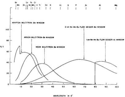
The relative sentitivities of the various detectors used are shown in Fig. 1.
The Multitron is used in the short wavelength region, and various types of flow Geiger for the longer wavelength region. The path length and window material in the flow Geiger provide some degree of physical discrimination against unwanted radiation.
Spectrometer systems
The components detailed in Table I and Fig. 1 may be combined in either fixed or scanning monochromators.
362 Physical methods of chemical analysis · E. DAVIDSON and W . RAMSDEN
cm Ne-He-Bu FLOW GEIGER-Al WINDOW
.0 2 0 3.0 4.0 5 0 6.0 7.0 8 0 9 0 10.0
WAVELENGTH IN A*
Fig. 1.—Relative spectral sensitivity of detectors.
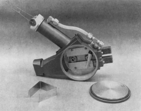
Fig. 2 shows a typical fixed vacuum monochromator, in which the crystal and slits are housed in a vacuum-tight die-casting. The length of the neck carrying the secondary slit and flow Geiger detector, and the angle of the neck to the case, are determined by the element being determined. Optical alignment of the crystal is effected by a double gear and rack system, which adjust for the correct Bragg-angle relationship between the crystal and the slits. The alignment of the vacuum monochromator is carried out from out- side the unit, without letting down the vacuum. Each fixed spectrometer is plugged into an array of primary slit cavities in the wall of the sample chamber. This facilitates replacement of the spectrometer unit following any major change in the analytical programme.
When a fixed wavelength monochromator can operate in air, i.e. for shorter wavelengths, the primary slit is sealed off with a Mylar window, and the optical elements mounted on an open plate which is indexed to the primary chamber.
A completely new design of scanning monochromator has been developed, the principle of which is illustrated in Fig. 3.
A relatively simple linkage, stainless steel cable, and pulley system continu- ously maintain the proper Bragg-angle relationship between the primary slit, the crystal, and secondary slit, and the detector. The motion effectively rolls the focal circle, created by the use of the curved crystal, through the primary slit for all wavelength settings, and permits linear wavelength readings to be taken off a drum dial and counter combination. The crystal
Fig. 3.—Principle of scanning spectrometer.
Fig. 2.—Vacuum monochromator.
364 Physical methods of chemical analysis · E. DAVIDSON and W . RAMSDEN
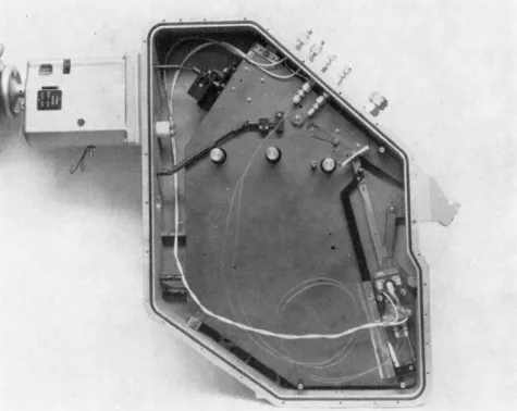
Fig. 4.—Scanning spectrometer housing.
is moved along a linear track by a leadscrew and nut combination, and is fixed to an isosceles triangle link, so that the crystal center line of curvature always passes through a mechanical center pivot. The isosceles triangle link, pivoted underneath the crystal center, has a sliding pivot moving in a linear track, which is oriented at 45° to the crystal travel. The third point of the triangle then becomes the mechanical center of the focal circle and rotates around the primary slit along an arc which is equal to the radius of the focal circle.
Vacuum lubrication problems and the relative simplicity of the linkage concept were the guiding factors in choosing the described design as the mechanism for the scanning monochromators. Another attractive feature of this design is the possibility of a self-adjusting secondary slit, whose width increases with wavelength as a function of the sine of the Bragg angle.
This overcomes one of the objections to a curved crystal geometry where the angular slit width decreases with increasing wavelength when a fixed slit is used.
Fig. 4 shows the described scanning mechanism in its vacuum tight housing with the cover removed. Alignment of the crystal for peak response is performed under vacuum from the exterior, by means of a shaft passing
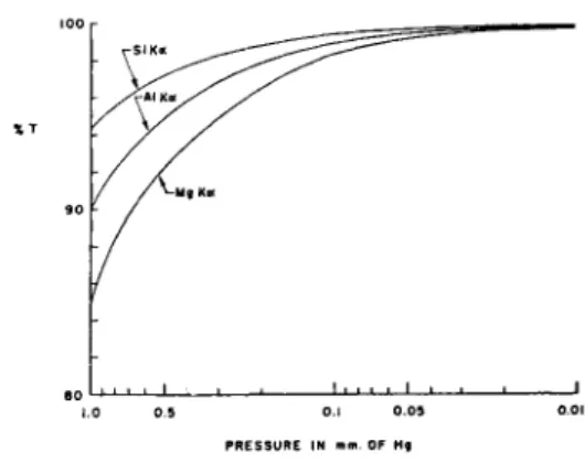
Fig. 5.—Variation of transmission with pressure at various wavelengths in
10 cm spectrometer.
1.0 0.5 0.1 0.05 0.01 PRESSURE IN mm. OF Hg
into the chamber through a vacuum tight bushing. Electrical connections for the detector are carried into the chamber through vacuum tight fittings.
The high voltage for the detector is completely insulated inside the vacuum chamber. Stainless steel capillary tubing is used to supply gas to the flow Geiger counter.
Scanning of the monochromator is performed from the exterior by means of a shaft entering the vacuum chamber in the upper left corner of the photograph. The scanning gearbox and revolution counter are shown attached to the outside of the vacuum case. Linear wavelength readings can be read off the revolution counter. In addition to the manual scanning, a motor drive provides automatic fast or slow scanning speeds of 0.1 A per min and 0.02 A per min.
Vacuum considerations
While the use of helium or hydrogen instead of air in X-ray spectro- meter systems results in some reduction of absorption, particularly above 3 A, a vacuum system is both more efficient and more economical.
In a vacuum X-ray spectrometer, time may be saved by ensuring that only the sample chamber is exposed to the atmosphere between runs.
This is readily accomplished by arranging matters so that the shutter which cuts off the X-ray beam also seals off the sample chamber.
When, after loading a sample, the system is pumping down, it is necessary to know at what stage in the process the analysis can be carried out without introducing any appreciable error due to variations in the intensities of the X-ray beam due to variations in the pressure of the system during a run, or from one run to another.
Fig. 5 shows the magnitude of the absorptions involved for certain im- portant elements in a 10 cm radius spectrometer. It is clear that in the range 0.5 to 0.1 mm, appreciable variations in intensity may occur with
366 Physical methods of chemical analysis · E. DAVIDSON and W . RAMSDEN
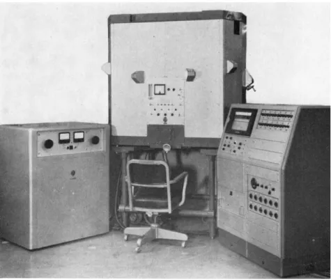
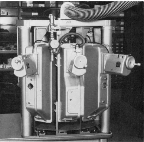
Fig. 6.—Complete vacuum production X-ray quantometer assembly.
differences in pressure. Below 0.1 mm, very little error will result from slight variations.
The analytical recording systems have therefore been designed so that analysis starts automatically when a pressure of 0.1 mm is reached, which is generally 20-30 sec after moving the sample to the analysis position.
T H E V A C U U M P R O D U C T I O N X - R A Y Q U A N T O M E T E R With the development of the Production X-ray Quantometer in 1958, simultaneous analysis of as many as 22 elements became possible. The vacuum version of the instrument has utilized the developments described in the preceding sections while maintaining the analytical coverage.
The basic spectrometer unit is rectangular in shape and accommodates up to 12 element spectrometers, placed radially round the sample and X-ray tube. The unit can be expanded to a dual unit by the addition of a semi- circular annex, resulting in a capacity of 22 element spectrometers. Each radial position can be occupied by two monochromators or one scanning spectrometer. U p to three vacuum scanning spectrometers can be provided.
Fig. 7.—Sample loading system—VPXQ.
The instrument may be mounted in the inverted position, as shown in Fig. 6. In this position liquids or loose powders may be examined without the interposition of a window, which would lead to intensity losses at long wavelengths. Where volatile liquids are being examined, the spectrometer unit may be flushed with helium, as an alternative to the vacuum mode of operation.
The unit can be operated in a manual or automatically programmed sequence for sample loading, evacuation, analysis, and sample removal.
Besides the normal safety interlocks, the vacuum system itself becomes an interlock since the X-ray shutter also acts as a vacuum gate valve, separating the main spectrometer housings from the sample chamber.
The motor-driven gate valve is operated during the pump-down period at a preset pressure, which can be varied by an adjustment of the trigger circuit in the vacuum gauge. A l l spectrometers are evacuated under normal operat- ing conditions, and only the sample chamber is returned to atmospheric pressure when a specimen is changed.
Fig. 7 shows the sample handling facility on the instrument; this uses a track and elevator system for convenience of sample loading. The maximum dimensions of a sample are 4 in. diameter, and 1 f in. in thickness.
368 Physical methods of chemical analysis · E. DAVIDSON and W . RAMSDEN
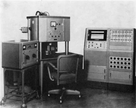
Fig. 8.—Complete vacuum X-ray quantometer assembly.
T H E V A C U U M X - R A Y Q U A N T O M E T E R
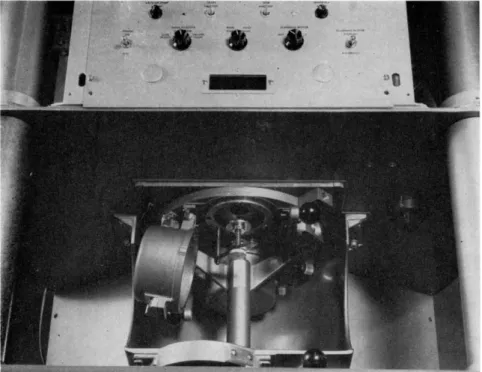
A new quantometer, called the Vacuum X-Ray Quantometer, embodies many of the above features, but deviates in some important aspects. Its capacity for element channels is limited to nine, which enables it to be a desk unit, and therefore, physically much smaller than the P X Q . This channel limitation is compensated for by a lower price and by a closer coupling between the X-ray tube and the specimen surface. Its higher optical speed permits faster analyses at precisions equal to those obtained with the P X Q . Fig. 8 shows the spectrometer in the centre, the recording console at the right, and the X-ray power supply and its control panel on the left. The schematic plan view (Fig. 9) of this instrument outlines its radial arrangement around the centrally located end window X-ray tube and the relative locations of its nine dispersive channels and one non-dispersive channel. The rear three positions can be taken up by scanning monochro- mators. Sample loading and sample analysing positions are diagramatically indicated. Fig. 10, a view of the interior of the instrument, displays the X-ray tube centered on the primary chamber to which the sample handling attachment is secured and which contains the primary slits, the X-ray
Fig. 9.—Spectrometer array—vacuum X-ray quantometer.
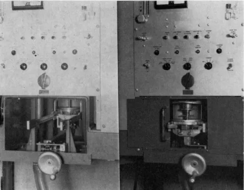
shutter, and the vacuum gate valve. The primary slit cells, selected for proper slit widths, are interchangeable and are accurately located in the primary chamber. The same fixed vacuum monochromator used in the larger instru
ment is shown in place on the primary chamber where it registers in the primary slit cavity. Profile control for the Bragg-angle adjustment of the crystal is accomplished from the outside of the instrument. Air channels for the analysis of the harder X-ray region fit into any of the nine dispersive
Fig. 10.—Interior of vacuum X-ray quantometer.
24-60143045 I & Μ
370 Physical methods of chemical analysis · E. DAVIDSON and W. RAMSDEN
Fig. 11.—Rear view—vacuum X-ray quantometer.
channel positions, and also register in the primary slit cavity. The primary slits for the hard X-ray region monochromators are covered with vacuum- tight Mylar windows.
A full complement of three scanners is shown in Fig. 11, a rear view of the instrument. The control boxes contain the appropriate gearing for a two- speed drive motor arrangement. The various features of these scanners, and their flexibility in accommodating a great variety of crystals and detectors permit their diversified applications for either research or production control.
The sample position relative to the X-ray optical system makes it feasible to use the X I P as a continuous process control instrument, as well as an analytical tool in the laboratory. In the standard instrument, two sample holders (Fig. 12) accommodating solid, liquid, and powder samples permit safe loading of one specimen while the other is being analysed. Each sample is enclosed in an X-ray proof cover housing which is mechanically and electrically interlocked against accidental exposure to X-rays. A sample
Fig. 12.—Sample loading systems—VXQ.
viewing system aids in placing the specimen on the proper portion of the sample selector disk. A variable primary collimator is adjusted by a control knob located to the right of the sample handling attachment. Three standard collimator sizes are used for the analyses of \ in., f in. and 1J in. diameter samples. Smaller specimens may be analysed with the aid of special colli- mator slides. The maximum dimensions of a sample than can be accom- modated in the dual sample selector are 3 in. in diameter and 1 in. in thick- ness. A n interesting feature in the design of this instrument is that when it is equipped with fixed monochromators for elements of atomic number greater than 19, none of the basic components protrudes lower than the surface of the sample. This means that the unit, without the dual sample selector, could be placed over or under a process stream in order to control up to nine elements with atomic numbers greater than 19 on a continuous basis anywhere in the process stream. The unit can also be used as a con- tinuous analyser on a process stream when equipped with up to three scanning monochromators. In this case, however, the scanning mono- chromator housings extend below the surface of the sample, and the distance which can be surveyed in from the edge of the process stream is limited.
Similarly, the distance in from the edge of the process stream, which can be
372 Physical methods of chemical analysis · E. DAVIDSON and W . RAMSDEN
T H E E M X - E L E C T R O N M I C R O P R O B E X - R A Y A N A L Y S E R In 1951, Castaing and Guinier at the University of Paris developed the first practical electron probe microanalyser. Several such instruments have now been placed in operation throughout the world, and many more are under construction.
The Electron Microprobe X-ray Analyser utilizes a finely focused electron beam to excite characteristic X-radiation from a very small volume at the surface of a solid sample. A s in X-ray fluorescence instruments, the wave- length and intensity of the X-ray lines are used to determine the elements which are present in the specimen as well as their relative concentrations.
All elements above atomic number 11 can be analysed.
The basic components of the instrument are (7) an electron beam system or probe, ( 2 ) a movable specimen stage, (3) a means for viewing the surface of the specimen, and (4) an X-ray analyser. Fig. 13 shows schematically the surveyed, is limited in the continuous X-ray analyser when elements of atomic number less than 20 are included in the programme. For elements of atomic number less than 20, the problem of creating a vacuum between the process stream and the X-ray analyser, or in flushing this region with helium or hydrogen, is a serious one and has not yet generally been solved.
Regardless of the detector used, the same recording system is employed for all elements. During the analysis, the detectors are connected to inte- grating capacitors, giving simultaneous charging of all capacitors for all elements. The integration time is controlled by source intensity, as measured by the nondispersive channel. In controlling the integration time, an alter- native to the nondispersive channel is the scattered radiation at some particular wavelength, as provided by one of the dispersive monochro- mators. This technique has provided some excellent results in the analysis of nonmetallics. When the analysis is terminated, either by the external nondispersive channel or the internal scattered radiation, the detectors are disconnected from their integrating capacitors. A vibrating condenser electrometer is rapidly connected in turn to the integrating capacitor as- sociated with each of the elements. Thus, the voltages on the simultaneously charged integrators are read out sequentially at the rate of one every two seconds, the results being traced on a recording strip chart. A digital volt- meter and electric typewriter combination is an alternative readout system to the strip chart recorder. Computers are now being developed to straighten working curves and provide third element corrections in optical emission analysis, which can be applied directly to X-ray fluorescence techniques when this recording system is used.
DIAPHRAGM VIEWING WINDOW FLUORESCENT SCREEN FIELD STOP DIAPHRAGM ILLUMINATOR MONOCULAR TUBE CROSS LINE DISC
EYEPIECE
STIGMATOR ADJUSTMENT REFLECTING OBJECTIVE SPECIMEN
MAGNETIC OBJECTIVE LENS MOTOR DRIVEN GATE VALVE -SPECIMEN SELECTOR
SPECIMEN ELEVATOR SPECIMEN TRAVERSE (X-Y) SPECIMEN ROTATION -SOLENOID VALVE -AUXILIARY VACUUM PUMP
VACUUM PUMP
MICROPROBE CROSSECTION SCHEMATIC Fig. 13.—Schematic—electron microprobe X-ray analyser.
relative positions of these components in the overall design, and Fig. 14 shows the layout of the complete instrument.
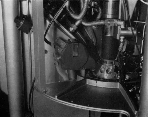
The instrument is operated from a sitting position, with sample handling, sample viewing and primary controls within convenient reach of the operator.
The electron probe forms the central column of the analyser unit, with an X-ray scanning spectrometer on each side, and a third X-ray spectro
meter extending to the rear opposite the operators position. The various power supplies and the vacuum equipment are housed beneath the sampling handling area. The high voltage power supply, on the right of the unit, allows accelerating potentials of 1-50 kV to be used with stepwise control in 500 V steps over the entire range so that voltage settings can be reproduced exactly. Regulation is 0.02 per cent for \ hr, 0.1 per cent for 4 hr.
The recording console is sited to the left of the analyser unit.
Electron beam system
The triode electron gun is a special design which permits centering of the filament with respect to the aperture in the grid while the gun is in operation.
Thus, rapid compensation for one of the principle causes of beam current
374 Physical methods of chemical analysis · E. DAVIDSON and W . RAMSDEN
Fig. 14.—Complete electron microprobe X-ray analyser assembly.
drift, viz., filament warpage, is permitted. Also, the filament can be changed in about 15 min without raising the entire vacuum system to atmospheric pressure by means of a valve which functions automatically when the gun is opened.
The gun filament is regulated by a D.C. supply from a transistorized amplifier and run under self-biased conditions with an externally adjustable self-biasing resistor. The supply avoids magnetic modulation of the beam current. It is possible to monitor the target current continuously or to use the integrated target current as a reference.
In many respects the design of the final lens of the electron optical system can be regarded as predetermining the performance capability of the instru- ment. The quality of this lens limits the minimum focal spot size which can be obtained with adequate current. Further, its size and shape limit the available space for the viewing system, the emergence angle of the X-rays, the smallest Bragg-angles which can be obtained with a given focusing-type spectrometer and in some cases, the maximum specimen size which can be accommodated.
The objective lens designed for the E M X features normal incidence of the electron beam on the specimen with an emergence angle of the X-rays of 52.5 degrees. This high angle gives better space resolution, better signal-to- noise ratio, and requires less critical sample surface preparation. With lower take-off angles shadows may be caused by irregularities in the polished sample surface. The magnetic field at the surface of the sample is only 10 gauss for normal operating conditions.
Sample stage
The sample chamber will accommodate eight specimens on a selector disc; after evacuation of the chamber (3 min) any of the eight specimens can be raised into the analysis position immediately. Maximum sample size is 1 inch diameter, ^ in. thick.
The stage displacement system provides three orthogonal translations and a rotation about an axis; two translations are parallel to the sample surface, and one normal to it; a linear translation of 0.4 in. in two perpendi
cular directions permits coverage of entire sample surface; translations are offset from sample centre to provide complete coverage. The axis of rotation is normal to the sample and the centre of rotation coincides with the centre of the sample.
A shoulder on the specimen holder insures adequate alignment of the specimen surface in the focal plane to allow a limited motion in the hori
zontal plane without vertical readjustments. The controls on the stage are sufficiently precise to allow repositioning of the sample to within 2 μ for repeated setting of the controls.
The horizontal controls of the stage or rotation control can be driven either separately or in any combination with a reversible, synchronous motor at a rate of 8 ///min; other speeds are available.
Viewing system
A Bausch & L o m b vertical illuminator with full and half aperture illu
mination, field aperture diaphragms, polaroid polarizers, etc., is utilized mounted on a door on the front of the instrument to facilitate removal for alignment purposes or for insertion of other viewing means.
Magnification is 280 x with a ten-power eyepiece.
Resolution is 1 μ, measured with a diffraction grating as the object.
Means are provided to adjust the position of the electron beam focal spot so that it coincides with the crosshair position in the microscope eye
piece. In this manner the exact spot being analysed may always be under visual examination.
376 Physical methods of chemical analysis · E. DAVIDSON and W . RAMSDEN
Vacuum system
A l l components of the electron optics, the X-ray spectrometer and the specimen, are operated in high-vacuum. Operating pressure is 2-5 x 10~5 mm Hg.
A mechanical "roughing" pump and a diffusion pump are employed to achieve the specified pressure level. A n auxiliary mechanical pump facili
tates the evacuation of the sample chamber. Appropriate Pirani, ionization, and thermocouple gauges are used to indicate the proper vacuum level.
Pump-down times: Entire system, 1 hr approximately; sample airlock chamber, 3 min; and electron gun airlock chamber, less than 1 min.
Safety interlocks are provided to protect all components against vacuum failure, accidental opening of vacuum chambers; the instruments meets all safety requirements regarding radiation hazards.
Analytical and recording systems
U p to three scanning spectrometers are available on the instrument, so that, using the curved crystal and detector components previously described, the best combination for any analytical programme can be provided.
The use of curved crystals is particularly suitable for the analysis of micro
scopic areas, due to the focusing properties of the curved crystal. Inter
change of crystals and detectors can be carried out within two hours, including diffusion pump-cooling period and evacuation time.
The E M X uses a standard A R L X-ray Recording Console as its readout device. A profiling circuit allows the instantaneous integrated intensity of any one of the outputs of the three spectrometers to be measured and con
tinuously recorded. Any count range can be employed and a time constant of 0.5 sec is available. A single 10 in. recorder is utilized, allowing readings to be made with an accuracy of 0.2 per cent.
A n integrating circuit allows the output of each detector to be stored on a separate integrator over any desired period of time. By means of an electro
meter amplifier, these integrated intensities can be read out sequentially on a pen recorder. Thus, simultaneous readings of three elements can be readily achieved, and automatic point-by-point plotting of all three on a traverse can be obtained.
A n interesting extension of the instantaneous readout system takes place when, during motorized sample traverse, at a rate of, say, 8 μ per min, the readout is switched, at, say, 2\ sec intervals, to each spectrometer in turn.
A record showing the relative distribution of all three constituents at spatial intervals of approximately 1 μ then appears on the recorder.
however, have been to problems in physical metallurgy.
Examples of metallurgical studies, which have been performed with a microanalyser are determination of the penetration of chromium in chro- mizediron, determination of nickel concentration in meteorites, identification of intermediate phases in a titanium-copper alloy, identification of phases in the titanium-silver binary system, determination of concentration fluc
tuations in a gold-copper alloy resulting from slow solidification, and deter
mination of the diffusion profile of nickel in single crystal sapphire. Other primary examples are the analysis of copper-zinc diffusion couples and the analysis of precipitates and inclusions. Extensive studies have been made on semiconductor materials.
Initial studies with the Electron Microprobe X-ray Analyser have demon
strated that extremely high sensitivity and line-to-background ratios may be obtained, even for high elements, in the analysis of microscopic areas.
The stability of the electron optics is such that analyses down to lower limits of concentration of about 0.01 per cent for the elements of atomic numbers from 12 to 92, can be achieved by a few minutes of integration with minimum spot size and on an absolute basis. By the use of relative measure
ments involving the beam current and use of increases in spot size, beam current, and time, these minima may be improved tenfold and thus reach the 0.001 per cent range for many elements.
Further developments, now in hand, will extend the scope of the Micro
probe instrument by providing electron beam scanning facilities. The distribution of any selected element in an area 360 μ square is presented on a cathode ray tube at a scanning rate of 120 lines/sec. Each frame of the cathode ray presentation is composed of 360 lines with each line representing 1 μ when the full 360 μ area is being observed.
C O N C L U S I O N
The developments described have resulted in an extension of the instrumen
tation available to those concerned both with routine analytical control of industrial processes, and with research investigations of microstructures.
The applications of these new instruments are now being investigated by several of the leading research laboratories in the U.S.A. and by A . R . L . Methods laboratories.