CHAPTER THIRTEEN
ELECTROCHEMICAL CELLS
The preceding chapter dealt primarily with the physical chemistry of electrolyte solutions; we now concern ourselves with the overall chemical process that occurs when electricity is passed through a conducting solution. The emphasis will be on the work associated with this overall change, as measured by the reversible cell potential. Since reversible work at constant temperature and pressure corre- sponds to a free energy change, we will thus be able to bring the emf of cells into the general scheme of thermodynamics. The chapter concludes with a discussion of irreversible electrode processes, that is, with the physical chemistry of the approach of ions to, and their reaction at, the surface of an electrode.
13-1 Definitions and Fundamental Relationships
A. Cell Conventions
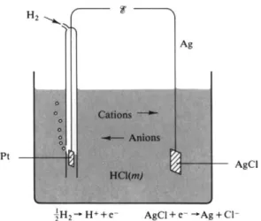
An electrochemical cell has, as essential features, a current-carrying solution and two electrodes at which oxidation and reduction processes occur, respectively, as current flows. Figure 13-1 gives a schematic example of a fairly typical cell for this chapter; we have hydrogen and silver-silver chloride electrodes dipping into an aqueous solution of HCl. The hydrogen electrode, incidentally, typically consists of a platinized platinum metal surface arranged so that hydrogen gas bubbles past as it dips partly into the solution, the object being to provide the most intimate possible gas-solution-metal contact. Platinized platinum is merely platinum metal on which additional, very finely divided platinum has been deposited electrolytically; the result is a high area, catalytically active surface. A silver-silver chloride electrode consists of silver on which a fine-grained, adherent deposit of silver chloride has been placed, again electrolytically. The terminals of the cell might be connected to a motor, so as to provide electrochemical energy, or, in the laboratory, to a potentiometer circuit (see Section 13-2), so that the potential difference could be measured.
499
FIG. 13-1. Schematic diagram of an electrochemical cell. The cell reaction is given by Eg. {13-2).
It is awkward to describe cells in a pictorial manner, and the conventional representation of the cell of Fig. 13-1 is
P t / H2( P atm)/HCl(m)/AgCl/Ag. (13-1)
Equation (13-1) is known as a cell diagram. The rule is that one writes in order each successive phase that makes up the electrical circuit of the cell, using a diagonal bar to separate phases. One should in general specify not only the tem- perature of the cell, but also the composition of each condensed phase and the partial pressure of any gaseous one; we assume the general mechanical pressure to be 1 atm.
A potentiometric measurement on a cell will report a potential difference between the electrode terminals, and the second convention needed is that to specify the sign of this cell potential There is some variation in practice and consequent ambiguity, and the least confusing way of stating the convention used here seems to be the following. We first define the cell reaction as the chemical change that occurs per faraday of electricity passed through the cell in the direction such that oxidation occurs at the left-hand electrode of the cell diagram. This electrode will be called the anode \ it is also the electrode toward which anions migrate in the cell solution as they carry current. The right-hand electrode of the cell diagram is then the one at which reduction occurs, and it is called the cathode;
it is also the electrode toward which cations migrate as they carry current. The cell reaction corresponding to (13-1) is
anode £ H2( 1 atm) = H+(m) + e~
cathode AgCl + e~ = A g + Cl"(m) (13-2)
net £ H2( 1 atm) + AgCl = A g + H+(m) + C\~(m).
Since the potential is a function of concentration as well as of the chemical species involved, statements of cell reactions should include the concentration or partial pressure of each substance.
The sign of <f is now defined to be positive if the cell reaction occurs sponta- neously in the direction written and to be negative if the reverse direction of reaction is the spontaneous one. In this particular example $ would be positive.
13-1 DEFINITIONS AND FUNDAMENTAL RELATIONSHIPS 501
F I G . 13-2. The Daniell cell.
That is, silver chloride is spontaneously reduced by hydrogen gas. Although the mechanical arrangement of the cell is such that the direct chemical reaction is prevented from occurring, the process will take place spontaneously when the electrode terminals are connected.
This last is an important feature of electrochemical cells. The cell reaction has to be spontaneous in one direction or the other, and the cell must always be so designed that the direct chemical reaction is physically prevented from occurring.
In the case of the cell of Eq. (13-1) the reactants H2 and AgCl are isolated at the separate electrodes. Another way in which direct chemical reaction is prevented is illustrated by the Daniell cell shown in Fig. 13-2; this consists of a zinc anode dipping into Z n S 04 solution and a copper cathode dipping into C u S 04 solution.
The two solutions are separated by a porous diaphragm which allows electrical contact but prevents gross mixing. The cell diagram is then
Z n / Z n S 04( w1)///C u S 0 4 ( w2) / C u , (13-3) where the dashed diagonal conventionally is used to indicate two miscible phases
that are physically prevented from mixing. This situation will later be referred to as one of a liquid junction. The cell reaction is
anode J Z n = JZn^Owx) + e~
cathode £ C u2+ ( m2) + e~ = C u (13-4)
net | Z n + J C u2 +( w2) = ^ Ζ η2 +( ^ χ ) + £ C u .
Again, the cell has been written in such a way that the cell reaction occurs spon
taneously—if placed directly into the C u S 04 solution, the zinc electrode would react as shown—and so the measured emf of this cell would be reported as positive.
To return to the matter of sign convention, we note that the usual source of confusion is in the plus and minus markings of electrodes. The cells of Figs. 13-1 and 13-2 are drawn so that in spontaneous action the left-hand electrode is the anode. This means that the anode bears a positive charge relative to the cathode at the solution end and a negative charge relative to the cathode at the exposed terminals. It is the terminals that are marked, hence it is the spontaneously operating
F I G . 13-3. Cell conventions. The cell diagram is anode/solution/cathode.
anode of a cell that bears the negative sign. To repeat, when we write a cell reaction the various signs and directions of flow are taken to be as shown in Fig. 13-3. If this is the spontaneous direction of flow, the £ is reported as a positive number.f
A further feature of electrochemical cells that are used in precise measurements is that they are reversible. That is, the cell reaction must take place readily in either direction. If the cell is short-circuited, the reaction should proceed in its spontaneous direction; and if an external potential is applied which overrides the natural cell potential, then the reaction should just as readily proceed in the opposite direction. The reversible electrochemical cell is thus one which may be held in a state of dynamic balance by application of an external counterpotential just equal to $ . For example, in the case of the Daniell cell £ is about 1.1 V if m1 = m2 = 1. External application of an opposing 1.1 V will just prevent reaction from occurring; a slightly smaller opposing potential will allow the cell reaction to occur as written, and a slightly larger opposing potential will make the reaction go in the opposite direction.
The customary way of determining $ for a cell is, in fact, to find that opposing emf which puts the cell in balance. The procedure thus defines cf as the reversible emf of the cell. If current is allowed to flow through the cell under conditions such that applied potential remains essentially equal to <f, then the work done is a reversible work. From the definition of potential, work in joules is given by qV, where q is the amount of charge carried through potential difference V. The reversible work for an electrochemical cell is then ntFi, where η is the number of faradays passed through the cell.
For the Daniell cell as written in Eq. (13-4), the reversible work is (96,487)(1.1) = 1.06 χ 105 J (mi = m2 = l, and 25°C). H a d the reaction been written for 2
Zn + C u2 +( m2) = Zn2+(mx) + Cu,
the reversible work would be 2.12 χ 105 J, and had the reaction been written in the opposite direction, β would be reported as —1.1 V and the corresponding reversible work would be —1.06 χ 105 J. Thus the sign of € and both the sign and magnitude of the reversible work depend on how the cell reaction is written.
f This is the traditional A m e r i c a n c o n v e n t i o n — a very logical o n e for physical chemists. T h e SI c o n v e n t i o n is discussed in Section 1 3 - C N - l .
13-1 DEFINITIONS AND FUNDAMENTAL RELATIONSHIPS 503
A useful conversion factor is that for η = 1 an emf of 1 V = 23.06 kcal. This unit is sometimes called the electron-volt: 1 eV = 23.06 kcal m o l e- 1.
B. Thermodynamics of Cells
The reversible emf that is measured for a cell gives the reversible work associated with the cell reaction. Since this is reversible work at constant temperature and pressure, it is therefore the free energy change and, by Eq. (6-34), the sign conven
tion is such that we must write
AG = -η&β\ (13-5) that is, a positive cell emf corresponds to a spontaneous cell reaction and hence
to a negative free energy change.
We may now rewrite several important equations of Section 7-4 in terms of emf's. Thus Eqs. (7-23) and (7-24) become
Δ * = "*(ΎΓ),- ( 1 3 "7 )
and, since G = Η — TS by definition, for a constant-temperature process we have
ΔΗ = AG + Τ AS, (13-8)
A H
= - ^ [ * -
T( W i } *
( i 3-
9 )ΔΗ* = -n& [*o -
r(-^)J.
(13-10)Equation (13-9) or (13-10) is known as the Gibbs-Helmholtz equation.
Example. T h e e m f o f t h e cell C d / s o l u t i o n saturated with C d C l2- 2 . 5 H20 / A g C l / A g is 0.6753 V at 2 5 ° C , and d&ldT = - 0 . 0 0 0 6 5 V Κ " Κ If w e write the cell reaction a s C d + 2 A g C l = C d C l2( s a t . soln.) + 2 A g , then AS = ( 2 ) ( 9 6 , 4 8 7 ) ( - 0 . 0 0 0 6 5 ) = - 1 2 5 J o r - 2 9 . 9 cal K "1 m o l e "l, AH = -(2)(96,487)[0.6753 - ( 2 9 8 . 1 ) ( - 0 . 0 0 0 6 5 ) ] = - 1 . 6 7 7 χ 1 05 J or - 4 0 . 0 8 kcal (as c o m pared with —39.5 kcal from thermochemical measurements), and AG = — (2)(96,487)(0.6753) = - 1 . 3 0 3 χ 1 05 J or - 3 1 . 1 4 kcal.
An interesting point is that the q for a reversibly operating cell is given by Τ AS; q would be — (29.9)(298.1) or —8.91 kcal in the example. In terms of Eq. (13-8) the measured q is given by AH when the reaction occurs directly, as in a thermochemical experiment; in the reversible cell the energy AG goes to do useful work, and the observed q is then determined by the entropy change. Thus the statement AH = AG + Τ AS amounts to saying:
. /energy available\ . /energy not available\
(total energy change) = ^ ^ ) + (t Q )
C. The Nernst Equation
A very important relationship is obtained as follows. For a general cell reaction
a A + bB + ··· = m M + n N + ···,
we have from Eq. (12-91) that
AG = AGQ + RTln Qth [Eq. (12-91)],
where, it will be remembered, 2th has the same form as an equilibrium constant but contains the activities of the products and reactants as arbitrarily specified by the stated reaction. If the system is at equilibrium, however, AG = 0, and we then obtain
AG0 = -RTln Kth [Eq. (12-92)], where A^th is the thermodynamic equilibrium constant.
Combination of Eqs. (13-5) and (12-91) gives the Nernst equation:
j ^ l n e t h . ( 1 3.n )
Insertion of the numerical constants for 25°C yields
g = - 0.02569 ln Qth = ** - \0 % Qth . (13-12) Equation (13-11) is the central equation of electrochemistry. By means of it we can determine how the emf of a cell should vary with composition, and we can also determine for a cell reaction, which in turn enables us to obtain activity coefficients for electrolytes.
Example. T h e Nernst equation for the cell reaction o f Eq. (13-2) is
# = _ 0.02569 in q H +*c l~ . (1 3.1 3)
A g and AgCl are in their standard states and hence have unit activity. The hydrogen pressure will be 1 atm, and, for the moment, we neglect activity coefficient effects, so Eq. (13-13) reduces to
# = <f ο _ 0.02569 l n [ ( H+) ( C l - ) ] = *0 - 0.05139 ln m. (13-14) The observed emf of this cell is 0.49844 at 25°C and m = 0.005 and we may use the Nernst equation
to calculate & for some other concentration, say 0.01 m. Since is a constant, it follows from Eq. (13-14) that
<^o.oim = <*Voo5m - 0.05139 ln = 0.46282.
The observed value is 0.46419, a difference we will shortly be attributing to the nonideality of aqueous HC1.
A s a different kind of example, for the reaction of the Daniell cell, Eq. (13-4), we have 1/2
<f = <?o _ 0.02569 ln 2g £ = ο 0.01285 ln .
If Z n2 + and C u2 + are at unit activity (or, very roughly, 1 m), & = 1.10 V at 25°C. This means that is also 1.10 V, since the log term is zero. If an excess of zinc metal is placed in a solution of copper sulfate which is initially at unit activity, the direct spontaneous reaction will occur to
13-2 EXPERIMENTAL PROCEDURES 505 form copper metal and zinc ion. Eventually the solution will consist of roughly 1 m or unit activity Z n2 + and some small equilibrium concentration of Cu2+. W e can use the Nernst equation to calculate this last. Since the final state is at equilibrium, AG and hence & must be zero, and so
«?o = i.io = 0.01285 In ( - ^ - )
\ tfCu2+ / equil
= 0.01285 In ( — — )
V 0 C u2+ / equil
T h e equilibrium ( C ua +) is then e x p ( - l . 10/0.01285), or a b o u t 1 0 "8 7 m(\).
13-2 Experimental Procedures
A. The Potentiometer
The reader is referred to experimental texts for details, but the principle employed in the measurement of emf's of cells should be described at least briefly. An elementary potentiometer arrangement is shown in Fig. 13-4. One sets up a closed circuit involving a working battery, usually a wet cell capable of delivering a reasonable amount of current without changing its voltage. The circuit contains a moderately high resistance, perhaps 1000 ohms, which is either in the form of a slide wire, or which may be tapped at close intervals. This resistance R then has an ohmic drop in potential iR across it. The electrochemical cell is connected as shown, with the electrodes in the same direction as for the working cell. One now moves the point of contact A until the galvanometer G shows no current flow. At this point the potential drop AB is the same as $ for the cell.
The circuit is usually calibrated by means of a standard cell, or one of accurately known emf $T e i. By determining point A' when the standard cell is in balance, one therefore knows the voltage drop A'B. The desired emf is then < ^re f ( ^ A B / ^ A ' B ) -
In actual practice one adjusts subsidiary resistances in the circuit (not shown) in calibrating with the standard cell so that the tapped or slide wire resistance posi
tion A will read directly in volts.
F I G . 1 3 - 4 . A potentiometer circuit.
A' A
^ΛΛΛΛΛΑΑΛΛΛΛΑΛΑΑΛΛΑΛΑΑΑννΛΛΑ^ C
X
Standard cell
6. Standard Cells
The most widely accepted reference cell is the Weston cell, illustrated in Fig. 13-5.
The anode consists of a layer of solid cadmium amalgam containing 12.5% cad- mium, and the cathode consists of a pool of mercury layered with a thick paste of H g2S 04. The solution is saturated with C d S 04 · f H20 , with some excess crystals present on both sides, to maintain saturation. The cell diagram is
Pt/Cd(Hg)/saturated C d S 04 · f H20 / H g / P t
and the corresponding cell reaction is
| H20 + Cd(amalgam) + H g2S 04W = C d S 04 · f U20(s) + 2 H g .
The emf at 25°C is 1.0183 V; the temperature dependence is small, —4.06 X 1 0 - - V K -1.
F I G . 13-5. The Weston cell.
Potentiometric measurements are among the most accurate of physical chemistry.
Cell potentials may be measured to about 10~5 V, the limiting accuracy usually being that of the voltage of the reference cell. If the unknown cell is one of very high resistance, then the sensitivity of the galvanometer may become the limiting factor. In the case of a pH meter, for example, the glass electrode may have 1 05o h m s resistance, and one must use a vacuum-tube null-meter to detect the balance point (early users of pH meters struggled with quadrant electrometers).
The potentiometric method is a null method—when the circuit is balanced the galvanometer shows no current flow, and a slight shift in the position of the contact A to one side or the other causes a galvanometer deflection in one direction or the other. A barely detectable galvanometer deflection need correspond to no more than perhaps 1 0- 1 2A , so the change in condition needed to reverse the current flow is very small and the measured potential is essentially the reversible one. If a relatively large current, say 1 0- 3 A, is drawn through a cell, then the potential drops as various irreversible processes occur, such as polarization, discussed in Section 13-9. The magnitude of the measured potential is therefore at a maximum at zero current.
13-2 EXPERIMENTAL PROCEDURES 507
(a) (b) F I G . 1 3 - 6 . Reference electrodes, (a) Calomel half cell, (b) Complete cell that includes a calomel
half cell.
C. Reference Electrodes
An electrochemical cell consists essentially of the two parts defined by the two electrodes, and one often constructs a cell in which one electrode is that under investigation and the other is a conventional electrode of known properties. This last is called a reference electrode. A very common and easily constructed one is the calomel reference electrode, illustrated in Fig. 13-6(a). Platinum wire dips into a pool of mercury which is layered with a paste of H g2C l2, followed by a solution which is usually 0 . 1 N K C 1 , 1 Ν KC1, or saturated KC1. Electrolytic connection must be made to the rest of the cell, and this is done through a side arm in which the KC1 solution has usually been stiffened with agar-agar or gelatine.
This type of electrolytic connection is known as a salt bridge (see Special Topics section).
A complete cell might then appear as in Fig. 13-6(b). The cell diagram is
P t / H g / H g2C l2( 5) / l JVKC1 or saturated KC1 / H a( n i ) / H , ( l atm)/Pt.
If the HC1 is at unit activity, then
<f2 9 8 = - 0 . 2 8 0 V ( l W K C l ) and <T2 9 8 = - 0 . 2 4 2 V (saturated KC1).
The boundary between the KC1 solution and that of the electrolyte of the second part of the cell is known as a liquid junction. Since ions are carrying the current in solution, passage of electricity means that ions move across the junction, just as in a transference experiment. In terms of this cell some K+ ions must move from the KC1 solution into the HC1 one, and some C I- ions must move from a concentration m in the HC1 to that in the KC1. Some net changes thus occur at the liquid junction, whose free energy requirement contributes to the emf of the cell as a whole. This contribution is known as the junction potential, and fortunately it is small if the bulk of the current is carried by oppositely charged ions of the same mobility. This is essentially the situation in the case of a KC1 salt bridge;
K+ and CI" do have nearly the same mobility. The more detailed treatment of junction potentials is given in the Special Topics sections, and it is sufficient
here to note that for most purposes the junction potential for a saturated KC1 (or a concentrated N H4N 03) salt bridge can be neglected. However, this effect does impair the accuracy of a cell involving a calomel reference electrode.
Other reference electrodes include the hydrogen electrode itself, which is very accurate but somewhat inconvenient to use, and well-known reversible electrodes such as the silver-silver ion or the silver-silver chloride ones. For accurate work a reference electrode should be a direct part of the cell, but it may be more con
venient to connect the electrode being studied to the reference electrode via a salt bridge and to either neglect or try to estimate the value of the junction potential.
13-3 Determination of
<$° Values and Activity Coefficients
Equation (13-11) may be written in the form
where
Q th aMrnau
RT In ρ RT
In ρν,
mn η ...
aAaaA<>
( M )m( N )n - 7 Μμ7 Ν " -
(A)"(B)» - γΑαγΒ» - = QQv •
(13-15)
(13-16)
We now write
RT RT
V = δ + ~ - l n Q = < f0 - In Qy (13-17)
The quantity $ ' is determined for a series of concentrations and plotted against concentration. At infinite dilution the activity coefficients and hence Qv approach unity, and In Qv approaches zero; the extrapolated value of is thus equal to #°.
The procedure may be illustrated for the cell corresponding to reaction (13-2)
0.236
F I G . 13-7. Determination of #0298 for the cell P t / H2( i a / m ) / H C l ( m ) / A g C l / A g .
13-4 ADDITIVITY RULES FOR EMFS. STANDARD OXIDATION POTENTIALS 509
at 25°C. We write Eq. (13-14) in the form
t = _ 0.05139 ln m - 0.05139 ln γ± or
r = e + 0.05139 ln m = ^ ° - 0.05139 ln y± . (13-18) According to the Debye-Huckel limiting law, Eq. (12-89), ln γ± should be propor
tional to y/m, so S' is plotted against \/m as shown in Fig. 13-7. Extrapolation to zero concentration gives #298 = —0.22239 V. Having determined the &° for the cell reaction, one may then insert its value back into Eq. (13-18) and thus obtain γ± for HC1 at each concentration.
This procedure illustrates how a number of very accurate values of β0 and of activity coefficients have been obtained. One may also, of course, estimate Qy either theoretically or from other activity coefficient data and thus calculate # ° from the measured <f.
13-4 Additivity Rules for
Emf s. Standard Oxidation Potentials
Since the δ or <f° for a cell reaction is just the free energy change per equivalent, emf's obey essentially the same additivity rules as do free energies. For example,
(a) Zn + 2H+ = Z n2 + + H2, (b) Cu + 2H+ = C u2 + + H2, (c) = (a) - (b) Zn + Cu2+ = Z n2 + + Cu.
We know that J G ?C ) = J G ?a ) — ^ G °b ), hence
o r ^ ! c ) = ^?a> ~~ ^α» · In general, if two cell reactions are added (subtracted), the resultant emf is the sum (difference) of those for the two reactions.
We make use of this attribute in much the same way as is done in formulating enthalpies and free energies of formation. First, all emf data are expressed as
$ ° relative to the hydrogen electrode as cathode. Second, a cell reaction is expressed as a combination of two half-cells. For example, reaction (a) is broken down as
Zn = Zn2+ + 2 e - ^ n / Z n2 + 2H+ + 2 e - = H2 - # £2/ H + Zn + 2H+ = Z n2- + H2 = < ^n / Z n 2 + - < ^/H+ '
Thus any cell reaction may be written as the difference between two half-cell oxidation reactions and any < f0 as the difference between two standard half-cell oxidation potentials. This combination of equations may therefore be written as
^7c> = ( ^ Ζ η / Ζ η2+ - ^ Η2/ Η + ) - ( ^ C u / C u « + — ^ H2/ H + )
= ^ Z n / Z n2 + ~~ ^ c u / c u2+ *
Some indirect estimates suggest that the absolute standard half-cell potential for H2/ H+ is small, but it is apparent that its actual value is immaterial in com
bining equations, since it cancels out. The third step is, accordingly, to make the convenient, arbitrary assignment that <^H2/H+ = 0 a nd to report the measured # ° values for reactions such as (a) and (b) as the actual values for the half-cells.
Thus = 0.763 and —0.337 for reactions (a) and (b), respectively, and we report that
^ n / z n - = 0.763 and < f °C u / C u 2 + = - 0 . 3 3 7 .
Then <^298 f °r reaction (c) is 0.763 — (—0.337) = 1.10 V; this result is independent of the assumption regarding <^H2/H+-
The convention is that the emf of a cell is given by
^ = ^ ef t- ^ l g h t , (13-1?)
where < f fe f t and ^i g h t are the standard oxidation potentials of the half-cells corre
sponding to the anode and cathode of the full cell, respectively.
The general mass of emf data has been reduced by means of this formalism and a number of standard half-cell potentials are given in Table 13-1. Their use follows the example just given. Each value is actually the <f0 for the cell whose anode is the stated half-cell and whose cathode is the standard hydrogen electrode.
The right-hand column of the table gives the corresponding standard electrode potentials, i^0. This alternative definition is described in Section 13-CN-l.
As one other further example, the reaction
(c) 2 H g + 2AgCl = H g2C l2 + 2 A g
can be written as the difference between
(a) 2 H g + 2C1- = H g2C l2 + 2e~, <sf°9 8 = - 0 . 2 6 7 6 and
(b) A g + CI- = AgCl + e-, <T2°98 = - 0 . 2 2 2 4 .
Then £fQ) = -(0.2676) - (-0.2224) = - 0 . 0 4 5 2 . Note that although we must multiply reaction (b) by 2 before subtracting it from reaction (a) in order to obtain reaction (c), we subtract the emf's directly. This is because an emf corresponds to the free energy change per faraday, so that all emf's are on the same basis.
There is one situation where the additivity procedure must be handled with care, namely in the combining of two half-cell reactions to give a third half-cell reaction. Each emf should be weighted by the number of faradays for which the half-cell reaction is written. As an example, consider the case
(a) F e = Fe2+ + 2e~, J G °a ) = - 2 # V? < a ) ,
(b) Fe2+ = Fe3+ + e~, AG φ) = —&δ%) ,
(c) F e = Fe*+ + 3e~, JG(°C ) = - 3 # t f(°c )
Since AG°ie) = AG°{&) + AG°ih), it follows that ^c ) = (2<f(°a ) + ^b )) / 3 . At 25°C, we get i ?c ) = [(2)(0.440) + (-0.771)]/3 = 0.036. The general equation is
^ = *(a ) * ? a ) + *<ι»*α» 9 ( 1 3.2 0 )
w(c)
13-4 ADDITIVITY RULES FOR EMF'S. STANDARD OXIDATION POTENTIALS
T A B L E 13-1. Standard Oxidation Potentials at 25°Ca
Half-cell reaction ^ 2 9 8 <v/-o b ' 298
Li = Li+ 4 e - 3.045 - 3 . 0 4 5
K = K+ + e - 2.925 - 2 . 9 2 5
Ca = C a2 + 4 2 e - 2.87 - 2 . 8 7
N a = N a+ 4 e~ 2.714 - 2 . 7 1 4
M g = M g2 + + 2 e - 2.37 - 2 . 3 7
Al = A l3 + 4 3 e - 1.66 - 1 . 6 6
Zn = Z n2 + 4 2e~ 0.763 - 0 . 7 6 3
F e = F e2 + 4 2e~ 0.440 - 0 . 4 4 0
Cd = C d2 + 4 2 e - 0.403 - 0 . 4 0 3
Pb 4 S O2" = P b S 04 4 2e~ 0.356 - 0 . 3 5 6
Tl = T1+ 4 e - 0.3363 - 0 . 3 3 6 3
Pb = P b2 + 4 2 e - 0.126 - 0 . 1 2 6
A g 4 I" = A g l 4 e~ 0.156 - 0 . 1 5 6
Fe = F e3 + 4 3e~ 0.036 - 0 . 0 3 6
H2 = 2H+ 4 2 e - 0.0000 0.0000
A g 4 B r - = AgBr 4 e~ - 0 . 0 7 1 3 0.0713
Cu+ = C u2 + 4 e - - 0 . 1 5 3 0.153
A g 4 CI" = AgCl 4 e - - 0 . 2 2 2 3 9 0.22239
Saturated calomel - 0 . 2 4 2 0.242
2 H g 4 2C1- = H g2C l2 4 2e~ - 0 . 2 6 7 6 0.2676
Normal calomel - 0 . 2 8 0 0.280
0.1 TV calomel - 0 . 3 3 5 8 0.3358
Cu = C u2 + 4 2 e - - 0 . 3 3 7 0.337
Cu = Cu+ 4 e" - 0 . 5 2 1 0.521
2 1 - = I2 4 2e~ - 0 . 5 3 5 5 0.5355
F e2 + = F e3 + 4 e~ - 0 . 7 7 1 0.771 2 H g = H g2 + 4 2 e - - 0 . 7 8 9 0.789 A g = A g+ 4 e" - 0 . 7 9 9 1 0.7991 H g2 + = 2 H g2 + 4 2 e - - 0 . 9 2 0 0.920 2 B r - = B r2 4 2e~ - 1 . 0 6 5 2 1.0652 J HaO = i Oz + H+ + e " - 1 . 2 3 1.23
T1+ = T l3 + 4 2e~ - 1 . 2 5 1.25
2C1- = C l2 4 2e~ - 1 . 3 6 1.36
P b S 04 4 2 H20 =
P b Oa + SOS" + 4 H+ + 2 e " - 1 . 6 8 5 1.685 2 F " = F2 4 2 e - - 2 . 8 7 2.87 Basic solutions
S O2" + 2 0 H - = SOJ- + H20 4 2e~ 0.93 - 0 . 9 3 H2 4 2 0 H - = 2 H20 4 2e~ 0.8281 - 0 . 8 2 8 1 N i 4 2 0 H - = N i ( O H )2 + 2e~ 0.72 - 0 . 7 2 3 0 H - = H20 4 H 02" 4 2e~ - 0 . 8 8 0.88
α Largely adapted from G. N . Lewis and M . Randall, "Thermo
dynamics," 2nd ed. (revisedby K. S. Pitzer and L.Brewer). McGraw- Hill, N e w York, 1961.
b See Commentary and N o t e s section.
where η denotes number of faradays. Whenever one has any question about combining cell emf's, he should always do so first in terms of AG's since these are always additive.
13-5 Emf and Chemical Equilibria
A. Thermodynamic Relationships
Combination of Eqs. (13-5) and (12-92), AG0 = -RTIn Kth , gives an impor
tant relationship between the # ° for a cell and the equilibrium constant for the cell reaction:
or, for 25°C
lntfth (13-21)
l o* * * = 005917 Λ ( 1 3"2 2 )
Thus for η = 1, 0.059 V corresponds to one power of ten in K.
6. Direct Applications
A very direct and useful application of # ° values is to the treatment of oxidation- reduction equilibria in solution. The following examples illustrate typical situa
tions.
Example. T o what extent will Z n reduce 0.01 m F e2 + at 2 5 ° C ? T h e reaction is Zn + F e2 + = Z n2 + + F e
and, from Table 13-1, °2 9 S = 0.763 - 0.440 = 0.323. T h e n Kth = exp[(2)(0.323)/(0.02569)] = 8.3 χ 1 01 0, or
8.3 χ 1 01 0 = .
a¥ e2 +
The reaction will g o virtually to completion, or, if activity coefficients are neglected, until ( Z n2 +) is essentially 0.01 w ; the equilibrium (Fe2+) is then 0.01/8.3 χ 1 01 0 = 1.2 χ 10"1 3.
Example. T o what extent should 0.01 m H g |+ disproportionate into H g a n d H g2 + at 2 5 ° C ? W e combine the following half-cell reactions:
(a) j H g2+ = H g2+ + e - , <f?a) = - 0 . 9 2 0 ,
(b) i H g2+ + e - = Hg(/), (f <°b) = 0.789,
(c) H g2+ = H g2+ + Hg(/), <?(0 = - 0 . 1 3 1 . Kth = e x p ( - 0 . 1 3 1 / 0 . 0 2 5 6 9 ) = 6.10* χ 1 0 "8, s o w e have
(Hg2+) (Hg2+)
6.10 x 1 0 "8 =
(Hg2+) 0.01 - (Hg2+)
13-5 EMF AND CHEMICAL EQUILIBRIA 513 f r o m which ( H g2 +) = 6.06 x 10 ~5. T h e calculation s u p p o s e s that s o m e H g ( / ) is formed or is present.
C. Determination of Solubility Products
Several of the half-cell reactions of Table 13-1 are written as the reaction of a metal with an anion to give a slightly soluble salt. The potential for such a half-cell reaction may be combined with the one for the simple oxidation of the metal, to give the solubility product of the salt. If we have
(a) Μ + X - = MX(5) + e~, ,
(b) Μ = M+ + e~, δ%) ,
(c) = (b) - (a) MX(5) = M+ + X - , <T(°C) = (f(°b ) - (f(°a ) , then, neglecting activity coefficients, K3P = exp(^(°c )/0.02569) at 25°C.
An alternative and sometimes very useful approach is the following. We write the Nernst equation for reaction (b):
' α » = - 0.02569 In aM + . (13-23)
The potential at a metal-metal ion electrode must always reflect the chemical potential of that ion; in the presence of X~, MX(i) forms, which decreases aM+ according to the solubility constant, aM+ = Kth/ax-. The standard potential of reaction (a) must therefore be the same as the potential of the metal-metal ion electrode for that value of aM+ which is present when ax- is unity. Thus when ax- is unity «f( b ) in Eq. (13-23) may be replaced by and <ζΜ + by Kth :
= *&> ~ 0.02569 In Kth , Kth = exp ^ ' t t '
which is the same result as before. This alternative treatment, although longer as presented here, becomes very advantageous when one is dealing with more com
plicated situations.
Example. Calculate the solubility product for A g2S 04 if # J9 8 = —0.627 V for the cell A g / A g2S 04/ H2S 04( m ) / H2/ P t .
The <?° is that for the half-cell reaction
2 A g + SOl~ = A g2S 04 + 2e~, * JM = - 0 . 6 2 7 . Subtraction of this from
2 A g = 2Ag+ + 2e~, <f2 9 8 = - 0 . 7 9 9 gives
A g2S 04 = 2 A g+ + S 04~ , * Μ β = - 0 . 1 7 2 .
The solubility product is then e x p [ ( 2 ) ( - 0 . 1 7 2 ) / 0 . 0 2 5 6 9 ] = 1.53 X 1 0 "e. N o t e that η = 2 in this case.
Application of the alternative procedure is as follows. W e write
# = - 0 . 7 9 9 - K 0 . 0 2 5 6 9 ) In a]
13-6 Concentration Cells
The term concentration cell is used to designate a cell whose net reaction involves only changes in composition of species (or of gas pressures) and no net oxidation or reduction. The <f0 for such a cell must be zero since all species in the cell reaction are then to be at unit activity, in which case no change at all accompanies the pas
sage of electricity.
When α8ο | - is unity, & = —0.627 V, and aAg+ = K/aS02- = K, so - 0 . 6 2 7 = - 0 . 7 9 9 - £(0.02569) In K, which gives the same result as before.
D . Determination of Dissociation Constants
The alternative procedure described in the treatment of solubility equilibria may be applied to a homogeneous equilibrium in solution. If a metal ion is com- plexed in solution, then the half-cell potential M/Mz+ gives the activity of that ion, and this often allows the calculation of the equilibrium constant for complexa- tion.
Example. T h e potential for the cell
C u / 0 . 0 2 / C u ( I I ) in 0 . 5 / N H3/ n o r m a l calomel electrode
is 0.26 V at 25°C. [We use formalities since the copper is largely present as the complex C u ( N H3) 5+
and we wish merely to describe the overall makeup of the solution.] W e treat the left-hand electrode as a C u / C u2 + electrode w h o s e emf is determined by aCn2+ in the solution: The emf of the cell is therefore written
' = < * c u / c u2 + - ^ r e f - £(0.02569) ln aCu « +
or
0.26 = - 0 . 3 3 7 - ( - 0 . 2 8 0 ) - ° ° ^5 6 9 in g 0 t t,+ f
( 2 X - 0 . 3 1 7 )
a c u t + = βΧΡ 0.02569 L91 X 10 '
Virtually all of the Cu2+ is in the form of C u ( N H3) J+; therefore ( N H3) = 0.5 - (4)(0.02) = 0.42, and we evaluate the equilibrium constant as
( C u ( N H3)2 +) 0.02 = 3 3? χ 1 0 1 0
(Cu2+)(NH3)* (1.91 X 10-»X0.42)4 M / * 1 U
(neglecting activity coefficients).
A number of equilibrium constants for the dissociation of complex ions have been determined in this way. We see in Section 13-8 that an analogous procedure may be applied to the determination of aH+ in a solution.
A. Electrode Concentration Cells
13-6 CONCENTRATION CELLS 515
A very straightforward type of concentration cell is the following:
ΡΙ/Η2(Λ)/Ηα(™)/Η2(Ρ2)/Ρί,
for which the cell reaction is
anode Η2(Λ) = 2H+(m) + 2e~, cathode 2H+(m) + 2e~ = Η2( Ρ2) ,
net reaction Η2(Λ) = H2( P2) ,
with
o im*Q
p _ 0.02569, P2 '298 - 2
In the case of a metal electrode the metal may be present as an amalgam:
Cd(xl, in H g ) / C d S 04( m ) / C d ( *2, in H g ) ,
with
0.02569, a.
— in ~x*
2 9 8 " 2 α '
Β. Simple Electrolyte Concentration Cells
In a simple electrolyte concentration cell liquid junctions are avoided by setting up two opposing cells which differ only in their electrolyte concentration. The following is an example:
A g / A g C l / H C l ( m1) / H2( l a t m ) / P t — P t / H2( l atm)/HCl(m2)/AgCl/Ag, first anode A g + Cl-imO = AgCl + e~, first cathode H+( m i ) + e~ = £ H2( 1 atm), second anode | H2( 1 atm) = H+( m2) + e", second cathode AgCl + e~ = A g + Cl"(m2), net reaction Η+ί/τίχ) + C\-(m^ = H+(m2) + Cl"(m2).
Note that it is important to write each ionic species separately if the electrolyte is in fact treated as fully dissociated. The emf for this cell is
<f2 9 8 = - 0 . 0 2 5 6 9 ln g H +» * »g c i" »m* ,
#298 = - 0 . 0 5 1 3 9 ln ^ - 0.05139 ln .
mx y± f W l
Cells of this type may be used to obtain the ratio of activity coefficients of an electrolyte at two different concentrations.
13-7 Oxidation-Reduction Reactions
W e consider here the situation in which both the oxidized and reduced forms of the half-cell couple are solution species. Examples are the couples F e2 +/ F e3 + and C u+/ C u2 +. Both partners of the redox couple are in solution, and since they can be exposed only to one of the electrodes (or else the cell would be short-circuited), it is mandatory that the second electrode be connected by means of a salt bridge. Thus we have
Pt/Cu+fwj), Cu2 +(m2)/standard calomel electrode.
The potential of such a cell is given by the general form
* = - - to S a S , (13-24)
where the anode reaction is
M(red) = M(oxid) + nor
and tfoxid and aTeu refer to the activities of the oxidized and the reduced forms of the species of the redox couple, respectively. A s mentioned in Section 13-2C, the presence of a liquid junction introduces some unavoidable inaccuracy in the measured emf. (See also the Special Topics section.)
Cells of this type have been used in the determination of the redox emf not only for metal ion couples but also for a variety of inorganic coordination compounds and for many organic systems.
A n example of the second type is the Fe(CN)J-/Fe(CN)J- couple, for which «?°9 8 = - 0 . 3 6 V, and an example of the latter is the couple
[ H O - CeH4- O H ] = [ 0 = C6H4= 0 ] + 2H+ + 2e~, - - 0 . 6 9 9 4 . (13-25) It will be seen in the next section that the quinone-hydroquinone couple is useful in /?H deter- minations.
Returning to inorganic examples, we note that most elements exist in several oxidation states and that the potentials between these states are generally determined by cells of the type repre- sented by Eq. (13-24). Table 13-2 summarizes a few of these emf relationships. The number between oxidation states is the standard oxidation potential at 25°C. W e assume acid solutions and use H+ and HaO as needed in writing the balanced half-cell reactions.
A cell corresponding to Eq. (13-24) may also be used to follow a redox titration. Let us say that ion M1 is initially present in reduced form and that an oxidizing agent, ion M2, is added progressively. The reaction
Mj(red) + M2(oxid) = M^oxid) + M2(red)
occurs. W e assume that the reaction is rapid so that at each stage of the titration the system is in equilibrium. Since there can be only one potential at the platinum anode, this means that aM (o xi d ) /
^ M j i r e d ) is always equal to flM2(oxid)/^M2 ( r e d ) -
The situation is most easily delineated by means of a concrete example. Consider the titration of Cu+ with Fe3+:
Cu+ + F e3 + = C u2 + + F e2 +. (13-26)
Electrolyte concentration cells having a liquid junction are discussed in the Special Topics section.
13-7 OXIDATION-REDUCTION REACTIONS 517 T A B L E 1 3 - 2 . Selected Standard Oxidation Potentials for the Elements
in Their Various Valence States'1
Cr ±2- Cr2+ Cr3+ C r202"
M n - H . M n2+ Mn3+ Μ η 02 M n O2" Μ η ΟΓ Fe — F e 2+ ~o m Fe3+
C o C o2+ C o3+ < z l ± C o O r
C u - ^ C u ^ - ^ ^ - C u2-
CI" Cl2 - ± i L HCIO - = ^ 5 - H C 1 02 C 1 03- C l O r
B r- J ± 5 L Br2 - = * i L H B r O B r 03"
I - 12 H I O i o3- J=^L H5I O6
α Adapted from W . M . Latimer, "The Oxidation States o f the Elements and Their Potentials in A q u e o u s S o l u t i o n , " 2nd ed.
Prentice-Hall, Englewood Cliffs, N e w Jersey, 1952.
The cell would be
P t / C u+( p l u s C u2 +, F e3 +, F e2 + as the titration proceeds)/calomel reference electrode.
The cell potential is £c e n = <^pt — <^ref» where ^P t is the half-cell potential at the platinum electrode. T h e statement is that at all stages o f the titration
<^Pt = < ^ F e 2 + / F e 3 + = < ^ C u + / C u 2 + , ( 1 3 - 2 7 )
= * 8. + / o « « + - 0 . 0 2 5 6 9 l n = - 0 . 0 2 5 6 9 l n , ( 1 3 - 2 8 )
where, for simplicity, activity coefficients are neglected. Equation ( 1 3 - 2 8 ) rearranges to
< ? 8 u, c u «+ - < a » + /Fe»+ = 0 . 0 2 5 6 9 l n
^VjffiV/ = °·
618· (
13"
29>
Equation ( 1 3 - 2 9 ) defines the equilibrium constant for reaction ( 1 3 - 2 6 ) and m a y be solved for each stage of the titration. O n e then inserts the equilibrium ratio of ( C u2 +) / ( C u+) or that o f ( F e3 +) / (Fe*+) in Eq. ( 1 3 - 2 8 ) to give < fP t and thence < ?c e U.
A t t h e e n d - p o i n t , F et ot = C ut ot, a n d since ( F ea +) = ( C u2 +) b y t h e stoichiometry o f E q . ( 1 3 - 2 6 ) , it f o l l o w s that ( F e8 +) = ( C u+) . E q u a t i o n ( 1 3 - 2 9 ) t h e n reduces t o
^ 8 u, c u » + - < ^ e « + , F e » + = 0 . 0 5 1 3 9 l n [ [ | ^ ]
Insertion of this relationship into the right-hand side o f Eq. ( 1 3 - 2 8 ) t o eliminate the log term leads t o
^ P t . e n d p o i n t = i( ^ F e2 +/ F e3+ + ^ C u + / C u2 +) - ( 1 3 - 3 0 ) E q u a t i o n ( 1 3 - 3 0 ) gives t h e value o f £P t a n d h e n c e o f <^Ceii at t h e endpoint. T h e plot o f this par
ticular titration is s h o w n i n Fig. 1 3 - 8 , where F i s t h e degree o f progress o f the titration.
- 0 . 2
°o - 0 . 4
- 0 . 6
- 0 . 8
0 0.2 0.4 0.6 0.8 1.0 1.2 F
F I G . 13-8. Potentiometric titration curve for Cu+ + F e8 + = C u2 + + F e2 +.
13-8 Determination of pH
The term pH was coined by S. Sorensen in 1909 to mean — log(H+), and we have come to use the symbol p{X) as an operator meaning —log X, where X may be a concentration, an activity, or an equilibrium constant; pK& means —log ΚΛ , for example. A potential measurement always reflects the activity of the species present, and only at infinite dilution can activity be equated with concentration.
Potentiometric methods for pH determination therefore measure some type of hydrogen ion activity, although it turns out that the exact nature of what is measured depends on the cell that is used. The modern procedure is to define pH as essentially
pH = - l o g aH + (13-31)
but with the exact meaning of aH+ determined by the cell used.
Consider first a cell such as (13-1):
P t / H2( l atm)/HCl(m)/AgCl/Ag.
The corresponding Nernst equation is
g = <fo - 0.05139 In a± t U C 1. (13-32) The procedure described in Section 13-3 allows the determination of and so
the cell measurements provide values for the mean activity of HC1 in any solution, which might be thought to correspond to aH+ . Suppose that now we replace the electrolyte by [ Η Α φ ^ ) + KC\(m2)]. The remains the same, as does Eq. (13-32).
However, the calculated mean activity for HC1 will now depend on both m1 and m2. Thus such a cell is not suited for pH determination.
Next, consider the cell
P t / H2( l atm)/solution / c a l o m e l electrode.
0