A P P L I C A T I O N S OF ULTRASONIC S TO A B L A T I O N STUDIE S
L . C. Lynnwort h Avc o Corporation
R e s e a r ch and Advanced Developmen t Division Wilmington , M a s s a c h u s e t ts
Abstract
Ultrasonic m e a s u r e m e n t of ablation rate during r e - e n t ry is p o s s i b l e, with a c c u r a c i es dependent on the m a t e r i al and t r a j e c t o r y. Studies of the variables that tend to frustrate u l›
trasonic ablation-rate m e a s u r e m e n t s r e v e al certain aspects of the ablation mechanism that ma y remain undetected, if no t for their influence on ultrasonic r e s p o n s e. Ultrasonic observations permit one to draw conclusions concerning char depth, and departures from s t e a d y - s t a te ablation.
Investigation of properties on which the ablation m e c h a › nism depends often overlooks the need for proper identifica› tion of test s p e c i m e n s, including identification of d e f e c t s. Ultrasonic evaluation of test specimens is nondestructive, and therefore economically alleviates this p r o b l e m.
Introduction
Ablative-type h e a t - s h i e ld m a t e r i a ls provide superior t h e r m a l protection of r e - e n t ry s y s t e m s, compared to nonab- lating m a t e r i a l s, when r e - e n t ry t r a j e c t o r i es induce high heat r a t e s. As ma y be expected, the numerou s requirements i m›
posed on heat shields are such that m a t e r i a ls fabricated from a single type of ingredient often lack desirable p r o p e r t i e s. Fortunately, h o w e v e r, by combining the advantages of two or m o re ingredients, a useful composite is frequently o b›
tained (JU 2).
T o improve the t h e r m al protection of r e - e n t ry s y s t e m s, the designer needs to optimize h e a t - s h i e ld composition and
145
SIXTH SYMPOSIUM ON BALLISTIC MISSILE AND AEROSPACE TECHNOLOGY
d i m e n s i o n s. His task is difficult because the r e - e n t ry e n v i›
ronmen t is hard to s i m u l a t e, and the r e s p o n se of new m a t e›
rials to the permutations of t h e r m o d y n a m i c - a e r o d y n a m i c e n›
vironment s defies description by easily m e a s u r ed p a r a m e t e r s.
Fo r ablative-type m a t e r i a l s, the mechanism of ablation, including the rate of ablation, continues to be of urgent i n t e r e s t. A numbe r of p a r a m e t e r s, each partially descriptive of the a b›
lation p r o c e s s, are interrelated through ablation r a t e. The search for these relationships has stimulated study of m o re than a dozen ablation-rate s e n s o r s.
Th e work reported here is an outgrowth of one such study, concerned with the feasibility of measuring ablation rate of a heat shield during r e - e n t ry by using ultrasonic t e c h›
niques .
Ultrasonic ablation gages based on p u l s e - e c ho or r e s o›
nanc e techniques are simple in principle. Thickness m e a s u r e›
men t by the p u l s e - e c ho technique depends on the elapsed t i me betwee n the sending and receiving of an ultrasonic p u l s e. Thickness m e a s u r e m e n t by ultrasonic resonance depends on the frequencies at which an exact numbe r of half wavelengths fit into the thickness of the m a t e r i al under t e s t.
Actua l m e a s u r e m e n t during r e - e n t ry tends to be f r u s› trated by hostile departures from ideal conditions. One should not expect ultrasonic ablation-rate values to p o s s e ss a c c u r a c i es muc h better than – 15 percent. The a c c u r a cy in a particular c a s e, of c o u r s e, depends on the particular heat
shield and r e - e n t ry t r a j e c t o r y.
O n the other hand, events that complicate an ablating m a t e r i a l ’s acoustic r e s p o n s e, such as endothermic reactions occurring in d i s c r e te reaction z o n e s, can be identified by properly interpreting their influence on the propagation of ultrasound. In this way, a deteriorated ultrasonic signal p r o›
vides a unique insight into certain details of the ablation m e c h a › n i s m . T h u s, a distinct feature of ultrasonic observations is that dynamic response to the conditions within a m a t e r i al can b e monitored, without disrupting those conditions, during the conduc t of the t e s t.
In this paper, the potential of ultrasonic observations is indicated by mean s of test results on an ablative-type h e a t- shield m a t e r i a l. H o w e v e r , the experimental procedures that are described are not confined to the study of ablative-type m a t e r i a l s. Rather, it is intended that the reader will direct
146
ultrasonic concepts, such as the reflection of sound from an elastic interface located within a s p e c i m e n, toward the s o l u› tion of his own p r o b l e m s. In this way, for e x a m p l e, the m o › tion of phase boundaries ma y be nondisruptively monitored.
A l so described is an elementary but often neglected a s›
pect of ablation studies. Unless m a t e r i al is nondestructively identified, the experimenter r i s ks extracting voluminous, but possibly w o r t h l e s s, data.
D i s c u s s i on
F r o m the analytic point of v i e w, an ablating composite is hardly m o re difficult to treat than, s a y, " p u r e" s i l i c a, p r o›
vided that o n e ’s conscience is not troubled by the additional assumption s which numbe r i n c r e a s es exponentially as the n u m › b e r of ingredients i n c r e a s e s. T h is suggests that h i g h - p e r› formanc e c o m p o s i t es of c o m p l ex structure augmen t the need for accurately m e a s u r ed m a t e r i a ls p r o p e r t i e s, and emphasize the corresponding need for e m p i r i c al verification of theoretical ablation b e h a v i o r.
Ablation r a t e, which ma y be defined as the velocity at whic h the g a s - l i q u id or g a s - s o l id interface r e c e d e s, is a u s e›
ful p a r a m e t er by which a m a t e r i al m a y be partly c h a r a c t e r i z e d. Definition of Heat-Shield Thickness
M e a s u r e m e n t of ablation rate s(t) during r e - e n t ry r e›
quires differentiation of h e a t - s h i e ld thickness s(t) with r e s p e ct to range t i me t . Any uncertainties in instantaneous values of s (t) will be aggravated by this differentiation p r o c e s s. T h e r e›
f o r e, the two surfaces whose separation is s(t) mus t be defined c a r e f u l l y, and their separation mus t be monitored frequently.
Th e back surface of the heat shield at any gage location ma y have a complex contour. H o w e v e r , this contour remains fixed relative to the metallic backup s t r u c t u r e. Let us then
simply define the back surface of the heat shielf to be the plane tangent to the back of the heat shield, at the center of the gage location.
Before defining the second boundary, it mus t be a p p r e c i› ated that when we ask how far an ablating surface is from the back s u r f a c e, the question is a disturbingly c l o se analog t o:
wha t is the altitude of a chain of c l o s e ly spaced, erupting v o l› c a n o e s? The appropriateness of this analogy has been
147
SIXTH SYMPOSIUM ON BALLISTIC MISSILE AND AEROSPACE TECHNOLOGY
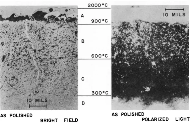
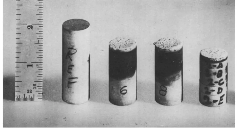
demonstrated repeatedly with m o v i es taken at from 200 to 4 00 f r a m e s per second, and by m i c r o s t r u c t u re studies (3) of c r o ss sections ( F i g. 1).
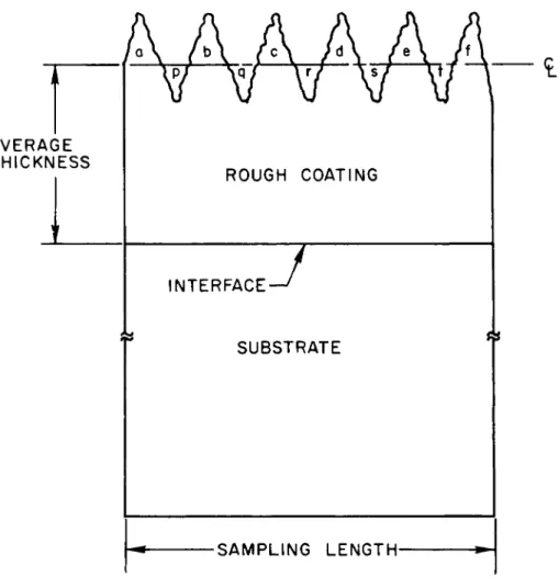
A second analogy ma y be taken from industries concerned with surface finish ( 4 - 8 ). Surface finish ma y be m e a s u r ed as f o l l o w s. A stylus drawn a c r o ss a rough surface coating will follow a path as shown ( F i g. 2). The average thickness ma y b e defined as tne distance between the interface and the c e n t e r- l i n e, positioned such that the sum of a r e as a, b, c, d, e, and f equals the sum of a r e as p, q, r, s, and t. Extending this idea to the c a se of the ablating heat s h i e l d, the second bounda›
ry that defines the h e a t - s h i e ld thickness in a s m a ll region ma y b e taken as a plane p a r a l l el to the back surface of the heat
shield, positioned such that the volume of peaks protruding abov e this plane equals the volume of valleys falling below.
Othe r definitions, equally a r b i t r a r y, are p o s s i b l e, of c o u r s e.
Before discussing the ultrasonic p u l s e - e c ho technique in detail, it is to be pointed out that this technique is not the only wa y of measuring ablation r a t e. Rather, the feasibility of m o r e than a dozen ablation-rate s e n s o rs has been s t u d i e d .* F u r t h e r m o r e , measuremen t of ablation rate is not an end in itself, but is preferably viewed as one of man y m e a s u r e m e n t s on which h e a t - s h i e ld design depends, and by which predicted t h e r m a l protection of r e - e n t ry s y s t e ms can be compared with flight data.
Principle of Ultrasonic Pulse Echo Technique
Thickness m e a s u r e m e n t by the p u l s e - e c h o, or e c h o- ranging, technique depends on the m e a s u r e m e n t of elapsed time between t r a n s m i s s i on and reception of a pulse of u l t r a›
sound . This ultrasonic pulse is generated and received by an electromechanical t r a n s d u c e r. At the m e g a c y c le frequencies required for accurate thickness m e a s u r e m e n t by the p u l s e - e c ho
#Som e of the methods for measuring ablation rate include s i l› houette movies (for laboratory use o n l y ), cineradiography with imag e intensification (for laboratory use only), X - r ay b a c k- s c a t t e r, plug containing discrete s o u r c es of gamm a r a y s, plug uniformly coated with radioactive m a t e r i a l, f i b e r o p t i c s, f o r› eign m a t e r i al plug ( s p e c t r o s c o p i c ), insulated w i r e s, magnetic w i r e s, t h e r m o c o u p l e s, p r e s s u r e - f i l l ed c a p i l l a r i e s, ultrasonic r e s o n a n c e, and the ultrasonic p u l s e - e c ho technique.
148
H SYMPOSIUM ON BALLISTIC MISSILE AND AEROSPACE TECHNOLOGY
Fig. 1. Cross Section of Type 1 Specimen after Ablation.
BRIGHT FIELD AS POLISHED
POLARIZED LIGHT AS POLISHED
149
SIXTH SYMPOSIUM ON BALLISTIC MISSILE AND AEROSPACE TECHNOLOGY
A V E R A G E T H I C K N E S S
R O U G H C O A T I N G
I N T E R F A C E
S U B S T R A T E
•SAMPLING L E N G T H -
Fig. 2. Accuracy and Interpretation of Ablation-Rate Measurements Depend Partly on Surface Finish.
150
technique, a p i e z o e l e c t r ic c r y s t al is the most suitable t r a n s› duce r element available. Using a single t r a n s d u c e r, a c c e ss to one side only is required ( 9 - 1 1 ). C o m m e r c i a l ultrasonic thickness gages sample thickness at rates from sixty to s e v e r al thousand t i m es per second.
M a t e r i al of Uniform V e l o c i t y. F or a uniform rod man y wavelengths in d i a m e t e r, the longitudinal velocity at which acoustic energy propagates depends on the m a t e r i a l ’s elastic properties and density:
vi
¯ 1 - ( 1 + ) ( 1 - 2) (1) wher e ¯ is Young’s modulus, is density, and ˇ is P o i s s o n ’sr a t i o. For a thin rod a fraction of a wavelength in d i a m e t e r, E q . (1) simplifies to = \/E/P
Fo r man y h e a t - s h i e ld m a t e r i a l s, such as reinforced plastics and r e s i n - c e r a m ic c o m p o s i t e s, is about 0. 1 Ø . / at room t e m p e r a t u r e. T h e r e f o re the wavelength at 1 m c is 0. 1 in. That is to say, sound waves at 1 m c travel through a h e a t - s h i e ld " r o d" man y wavelengths in diameter at a velocity determined by E q. (1).
If the h e a t - s h i e ld thickness is s , then the round trip t i me for a pulse is
r = 2 s/v (2)
In E q. ( 2 ), velocity dispersion is n e g l e c t e d. V e l o c i t i es of propagation for a wave train of finite length is given in Stratton ( 1 2 ). Use of E q. (2) is further limited by the u n s y m m e t r i c al deterioration of pulse shape, due to the greater attenuation of high-frequency Fourier component s of the p u l s e, compared to the l e s s er attenuation of low-frequency components. Pulse deterioration is d i s c u s s ed in ( 1 3 ).
M a t e r i al of Nonuniform Velocity -- Variation of Velocity With T e m p e r a t u r e. In view of E q. ( 1 ), if a material is heated from one s i d e, three causes of velocity variation through the thickness can be anticipated i m m e d i a t e l y:
1 5 1
SIXTH SYMPOSIUM ON BALLISTIC MISSILE AND AEROSPACE TECHNOLOGY
a. Variation of Young’s modulu s at elevated t e m p e r a›
t u r e s,
b . Variation of density at elevated t e m p e r a t u r e s, and c. Variation of P o i s s o n ’s ratio at elevated t e m p e r a›
t u r e s.
T h e s e variations take into account c h e m i c al change brought abou t by heating the s p e c i m e n, if such changes o c c u r.
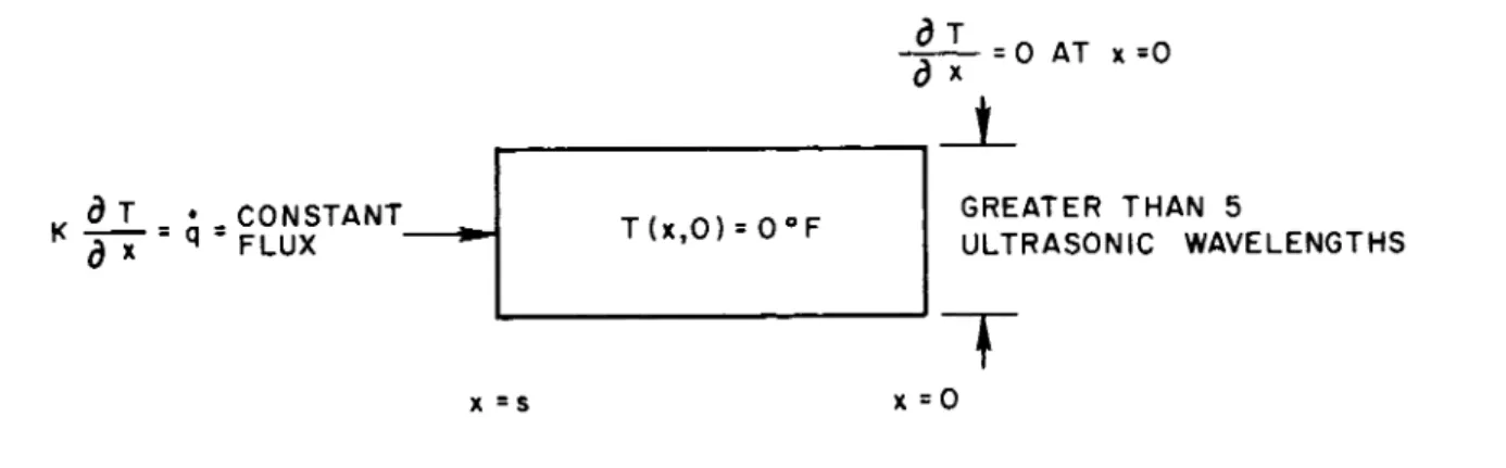
A slab bounded only by two p a r a l l el p l a n e s, at = 0 and = s is presented (Fig. 3 ). A constant t h e r m al flux q is a p›
plied to one s u r f a c e, and there is no radial heat t r a n s f e r. Fo r this o n e - d i m e n s i o n al heat-conduction m o d e l,
ν = v ( x ) (3)
an d the round trip time is
provided that the echo a r i s es from the f a r, hot end ( x = s ). T o evaluate v ( x ) , one can first compute the temperature d i s t r i› bution in a finite slab subject to a constant flux by using the
solutions to the heat-conduction equation dT d2T
dt DX2 (5) given in Car slaw and Jaeger ( 1 4 ). T e m p e r a t u re distributions hav e a l so been evaluated for transient fluxes ( 1 4, 15).
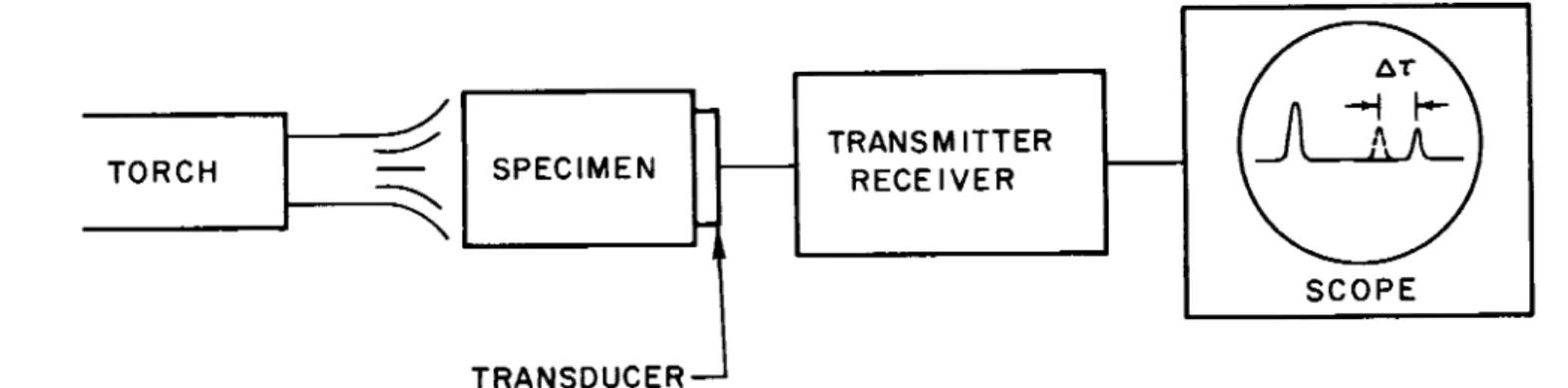
Next , one can m e a s u re v(T) by using a notched specimen ( F i g. 4) ( 1 6 ). Knowin g T( x ) and v(T) , one can obtain v ( x ) for use in E q. ( 4 ).
B e c a u s e elastic constants are frequency-dependent as wel l as temperature-dependent (the two dependencies are r e›
lated), the need for a setup s i m i l ar to that shown ( F i g. 4) should not be overlooked. One mus t avoid the temptation of computin g v(T) by substituting r e s u l ts of static t e s ts into
1 52
H SYMPOSIUM ON BALLISTIC MISSILE AND AEROSPACE TECHNOLOGY
< ˇ
(/>
O-J
II
Η*
155
GREATER THAN 5
ULTRASONIC WAVELENGTHS
Fig. 3. Material of Nonuniform Velocity.
SIXTH SYMPOSIUM ON BALLISTIC MISSILE AND AEROSPACE TECHNOLOGY
- * - N - * - \
\ Ν
Ø
œ ˆ ~ /
U L T R A S O N I C T R A N S D U C E R- Z O N E O F U N I F O R M T E M P E R A T U R E Τ
1 5 4
F i g. 4. For This Notched Specimen, v(T) = 2˝ / ( ˆ 2-ˆ ) .
= vE/ p • For e x a m p l e, one ablative-type r e s i n - c e r a m ic composite has a static Young’s modulu s of ¯ = 0. 64 10^ p si
= 4 . 42 10 d y n e s / cm ^, and a density of - 1. 3 g / c c, at room t e m p e r a t u r e. Use of = \JE/P yields a " z e ro f r e q u e n c y"
velocity of 0. 073 in. / s e c, which is about 35 percent below this c o m p o s i t e ’s room t e m p e r a t u r e, 1 m c velocity of 0. 114 in. / s e c.
Th e temperature coefficient of velocity depends on the m a t e r i al and environment. The effect of the temperature d i s› tribution on round trip t i me can be evaluated to the extent that the m a t e r i a l ’s properties a re know n functions of t e m p e r a t u r e.
E x p e r i m e n t a l l y, the temperature effect can be easily demonstrated ( F i g s. 4 and 5 ). The specimen is heated, and the shift in echo position is o b s e r v e d. F or most s o l i d s, v e l o› city d e c r e a s es as temperature i n c r e a s e s. One notable e x c e p›
tion is quartz, where velocity i n c r e a s es linearly with i n c r e a s› ing temperature up to about 1000 C, according to the equation
= a T + b (6) wher e a = 1. 58 1 0 ’5 in. / ^ s ec C, and b = 0. 229 – 0. 0 02 in. /
ptsec. The values for a and b have been m e a s u r ed by support›
ing a quartz rod on thin w i r e s, and observing the frequencies at which the rod can be resonated. Using these values in E q.
(6) yields v e l o c i t i es about 4 percent below values given in the literature ( 1 7 - 1 9 ), for a slightly different grade of quartz. This d i s c r e p a n c y, while s m a l l, i l l u s t r a t es the need for c o m › plete s p e c i m en identification, a point which w i ll be expounded later in this p a p e r.
Since the ultrasonic r e s p o n se of ablating m a t e r i a ls is of p r i m a r y interest h e r e, let us compute the change in round trip t i me attributable to the t e m p e r a t u re distribution in an ablating quartz heat shield where thickness d e c r e a s es at the constant rate s ( 2 0 ). In E q s. (7) to ( 1 3 ), we will take s , the rate at whic h thickness d e c r e a s e s, as a positive n u m b e r . The s t e a d y-
state t e m p e r a t u re distribution T( y) has been shown to be (21)
T( y) = Tw e -8? /* (7)
wher e Tw is the amoun t by which the temperature of the a b l a t› ing surface exceeds the c o o l, infinitely distant backsurface
155
SIXTH SYMPOSIUM ON BALLISTIC MISSILE AND AEROSPACE TECHNOLOGY
156
Fig. 5. Echo Position Show s Change in Round Trip Time ˜ as Specimen is Heated.
LU ˇ 3 ˇ
ω ζ <
(Τ I—TRANSMITTE R RECEIVER SPECIMEN
TORCH
SCOPE
t e m p e r a t u r e, y is a coordinate m e a s u r ed into and n o r m a l to the ablating surface (origin at ablating s u r f a c e ), and A is the t h e r m a l diffusivity. It is to be noted that when a m a t e r i al de›
c o m p o s e s during ablation, p o s s i b ly giving r i se to subsurface endotherms , e x o t h e r m s, or t h e r m al a r r e s t s, E q. (7) ma y provide a rather c o a r se approximation to the actual t e m p e r a›
ture distribution, even if " e f f e c t i v e" t h e r m al diffusivity is u s e d .
F r o m E q s. (6) and ( 7 ),
= a e w - s y /Æ +
(8)
If s(t) is the thickness of the m a t e r i al at t i me t , the round trip t i me is
r(0
/ (t) s(t)
dy
-SY/A + b (9)
2s(t) 2 a ,
+ In b HI
b + a Twe -i [ (st) ] /a
b + a (10)
wher e s is a s s u m ed to be approximately constant during i n t e› gration. If E q. (7) is approximately c o r r e c t, then ~8^Ø^ / « 1 , an d E q. (10) simplifies to
2s(t) 2A / a \ r(t) = - In (l + T )
b BK \ b / w ( ID
If d e s i r e d, E q. (11) ma y be factored into the form
r(t)
2e(t)
SIS(t)] V b / w (12)
157
SIXTH SYMPOSIUM ON BALLISTIC MISSILE AND AEROSPACE TECHNOLOGY
Assumin g E q. (6) holds out to the receding s u r f a c e, and taking Tw = 2 0 0 0 C, s = 1 in. , Æ = 1. 2 54 1 0 "3 in.2/s e»c s" u b
stitution in E q. ( 1 1) gives the round trip t i me in s e c:
1.87 x l 0 ~3 . r ( t) = 8.73 - : (1 3>
wher e s is m e a s u r ed in i n . / s e c. Thus for ablation rates greater than a few hundredths of an inch per second, the effect of the s t e a d y - s t a te temperature distribution in quartz is to d e c r e a se the round trip t i me by l e ss than 0. 1 s e c.
Fro m these calculations, E q s. (7) to ( 1 3 ), one ma y g e n›
e r a l i ze that the temperature distribution, in quartz or other m a t e r i a ls having a temperature coefficient of velocity of the order of 1 0 i n . / s ec C, has but a s m a ll effect on round trip t i m e, and therefore need not be considered as having an i m p o r›
tant influence on ultrasonic r e s p o n s e. H o w e v e r , the numbe r of assumptions inherent in this calculation invalidates this conclusion. One of the assumptions is that the echo a r i s es from the g a s - l i q u id interface at the ablating end. On the c o n›
t r a r y, ultrasonic studies of s o me r e s i n - c e r a m ic c o m p o s i t es hav e shown the observed echo to a r i se from an elastic i n t e r› face as muc h as an eighth of an inch away from the ablating s u r f a c e. To explain this elastic i n t e r f a c e, the variation of velocity with t e m p e r a t u re mus t be c o n s i d e r e d, as will now be seen. (Transition t e m p e r a t u r es at which ultrasonic velocity an d expansion coefficient change abruptly are d i s c u s s ed briefly elsewhere ( 2 2 ). )
Impedance . Impedanc e ma y be considered the ratio of cause to effect. In a c o u s t i c s, three impedance ratios are of i n t e r e s t. The first of these is the c o m p l ex ratio of the sound p r e s s u re to the particle velocity at a given point in a wave field, and is called the specific acoustic impedance. If an u n›
bounde d plane wave propagates in one direction, the specific acoustic impedance is simply the d e n s i t y - v e l o c i ty product pv, the characteristic impedance.
A second impedance ratio, the mechanical i m p e d a n c e, is force divided by particle v e l o c i t y. The third r a t i o, acoustic impedance , is sound p r e s s u re divided by volume v e l o c i t y.
T h e s e three definitions of impedance ratio will not be further d i s c u s s ed h e r e, as they have been adequately treated in man y texts ( 1 0, 1 1, 2 3 ).
158
Reflection from an E l a s t ic Interface. Whe n an acoustic wav e propagating in a medium of c h a r a c t e r i s t ic impedance ZQ
encounters a medium of c h a r a c t e r i s t ic impedance , the i n t e r› face between the two media being perpendicular to the direction of propagation, the degree of impedance m i s m a t ch determines the relative amount s of energy that are reflected and t r a n s m i t› t e d. The complex reflection coefficient, which is the ratio of reflected to incident p r e s s u r e, is (24)
Z
1-Z
0<Z
X/2 .
0)-l
R
.|
R|
e.*.,
R|fc_._ - _____
{ 1 4 )If there is no sound absorption, ZQ , Zj , and R a re pure r e al n u m b e r s . If there is absorption, ZQ , Z j, and R a re c o m p l e x, an d f u r t h e r m o r e, weak echoes ma y not be detected.
F r o m the foregoing, it should be clear that echoes can a r i se not only from the end of an ablating s p e c i m e n, but also from any interface between regions of different i m p e d a n c e s.
Fo r certain ablating r e s i n - c e r a m ic c o m p o s i t e s, the existence of s e v e r al regions of different impedances is quite plausible ( F i g s, i and 6 ). By sectioning ablated speciments (Fig. 6 ), distinct reaction zones have been indicated. According to one m o d e l for this r e s i n - c e r a m ic composite (3), zone A is a thin layer of molten s i l i c a. Zones B, C, and D a re thin reaction z o n e s. Zone ¯ is undecompose d m a t e r i a l. (The notation 2 - A, 2 - B, . . . , 2E of F i g. 6 b e a rs no relation to the zone notation A to ¯ of F i g. 1. ) The amoun t of sound s p e c u l a r ly reflected from a particular e l a s t ic interface located s o m e›
wher e between different reaction zones depends on the s e v e r i ty of impedance gradient encountered by the sound, and on the smoothnes s of the interface.
Although the liquid-gas interface at the ablating end r e›
flects over 99 percent of incident acoustic e n e r g y, the reflected energy ma y be l a r g e ly n o n s p e c u l a r, and rapidly attenuated. T h e r e f o r e, compared to its r e s p o n se to the end echo, a t r a n s› duce r ma y respond m o re vigorously to a pulse reflected from s o m e elastic interface having a reflection coefficient of only
10 p e r c e n t, provided that the elastic interface echo is s p e c u l a r› ly r e f l e c t e d, and f u r t h e r m o r e, not o v e r ly attenuated during its return trip to the t r a n s d u c e r.
Thu s a recently recognized p r o b l e m, where solution r e›
veals interesting aspects of the ablation m e c h a n i s m , is the
1 5 9
SIXTH SYMPOSIUM ON BALLISTIC MISSILE AND AEROSPACE TECHNOLOGY
160
Fig. 6. Whe n Ablated Surface is Not Norma l to Specimen’s Axis, Silhouette Provides False Indication of Specime n Length.
location of sound-reflecting interfaces and identification of their correspondence to c h e m i c al boundaries, such as the boundar y of an endotherm or c h a r, to thermodynami c bound›
a r i e s, such as a plane at which specific heat is discontinuous ( 2 2 ), or to physical b o u n d a r i e s, such as a l i q u i d - s o l id or liquid-gas interface. Obviously, these " c h e m i c a l ," " t h e r m o›
dynamic , " or " p h y s i c a l" boundaries are interrelated. One of the purposes here is to demonstrate that the relationships can b e identified by their effects on ultrasonic w a v e s.
According to ( 3 ), the c h e m i c al reaction z o n e s, in which temperature gradients are confined, are separated from one another by i s o t h e r m al i n t e r f a c e s. The surface temperature (liquid-gas interface) of ablating silica is estimated as 2 0 0 0 C.
Proceeding into the ablating r e s i n - c e r a m ic c o m p o s i t e, the A -B interface is a 9 0 0 C i s o t h e r m, the B -C interface is 6 0 0 C, the C -D interface is 3 0 0 C, and the D -E interface is 100 C.
T h e s e t e m p e r a t u r es are shown above ( F i g. 1).
Le t us now review recent ultrasonic t e s ts on an ablating h e a t - s h i e ld m a t e r i a l.
Experiment s Using P u l s e - E c ho Techniques
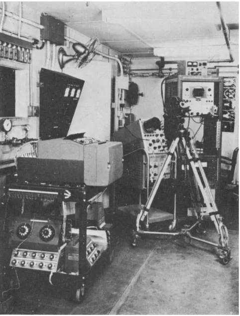
Initial Experiments -- T e st Setup. The test setup in whic h cylindrical specimens have been ablated in splash t e s ts using a 250 kw p l a s ma arc facility is shown ( F i g. 7 ). S p e c i›
me n m a t e r i al will be designated Type 1, which is a r e s i n- c e r a m i c c o m p o s i t e.
This composite m a t e r i al is generally fabricated as a large ring. The ring, after v i s u al inspection and m e a s u r e›
men t of bulk density, is radiographed to determine soundness an d uniformity of density. A radiographically acceptable structure is further subjected to an ultrasonic inspection p r o›
c e d u r e, to determine uniformity of ultrasonic velocity and a t›
tenuation. If the m a t e r i a l ’s r e s p o n se to the foregoing nonde›
structive t e s ts shows it to be representative of Type 1 m a t e›
r i a l, then test s a m p l es ma y be machined from the ring ( 2 5, 2 6 ). Fo r the t e s ts to be described b e l o w, s p e c i m e ns are c o r- ings of from 3 /4 to 7 /8 in. d i a m e t e r, and from l - l /4 to 2 in.
long. T h e se lengths are sufficient to t h e r m a l ly insulate the transducer for 30 seconds from the onrushing, heated air with temperature reaching 1 2 , 0 0 0 F as stagnation enthalpies range from 3400 to 1 0 , 0 00 B t u / l b. Heat flux is about 1000 B t u / f t2s e c.
161
SIXTH SYMPOSIUM ON BALLISTIC MISSILE AND AEROSPACE TECHNOLOGY
A
L I G HT S O U R CE R E F E R E N CE R OD- S I L I C O NE G R E A SE C O U P L A NT
R E C O R DS S P E C I M EN L E N G TH
S P E C I M EN
π
A RC C A M E RA
E C HO I MC U L T R A S O N IC
T R A N S D U C ER M A IN B A NG A X I A L LY
S Y M M ET C O N N E C T OR
I F I ER ^ I
S Y M M E T R IC n2 kv
3R
I
1_ˇ S EC
D C P U L S ER ( I M M E R S C O PE )
R E C E I V ER
71
R E C O R DS U L T R A S O N IC R O U ND T R IP T I MF
O S C I L L O S C O PE ( T E K T R O N I X)
U L T R A S O N IC C A L I B R A T I ON T I ME IN A RC
fO S EC
’ 3 0 S EC
0 I 2
S P E C I M EN L E N G T H, in.
F i g. 7. Experimental Setup for T e s ts in A rc F a c i l i t y.
1 6 2
Th e profile of the ablating specimen is recorded at 1 sec intervals by mean s of the arc c a m e r a. Using a film r e a d e r, the projected silhouette is read to – 0 . 0 0 15 in. H o w › e v e r, this a c c u r a cy has been misleading when the ablating surface is inclined at an angle to the silhouette c a m e r a ’s line of sight ( F i g. 6 ), when the ablating surface is cupped or when the index of refraction has varied near the s p e c i m e n. (See
section on silhouette i m p r o v e m e n t s. )
A 1 m c ultrasonic transducer is driven by a d -c p u l s e r. About 4 00 t i m es per second, a pulse of ultrasound is transmitted down the s p e c i m en until, near the end of the s p e c i›
m e n , a s e v e re impedance m i s m a t ch is encountered. The r e›
flected energy (after detection) appears as the echo on the o s c i l l o s c o p e, and the round trip t i m e, m e a s u r ed from the leading edge of the main bang to the leading edge of the e c h o, provides a m e a s u re of s p e c i m en length.
On e ma y view the two c a m e r as as providing coordinates for the plot labeled " u l t r a s o n ic c a l i b r a t i o n" ( F i g. 7 ).
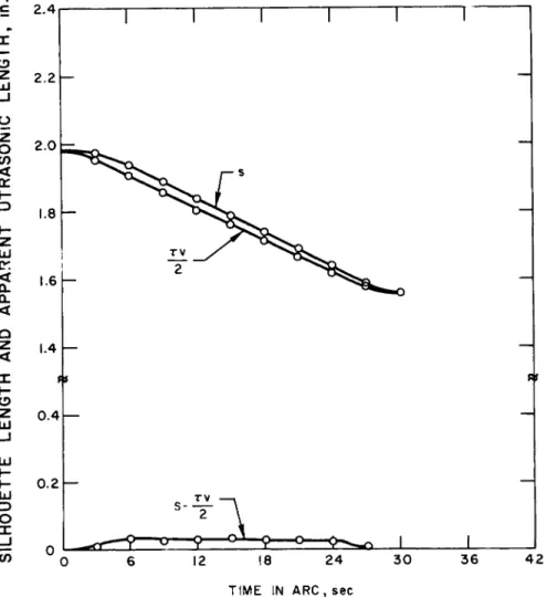
Initial Experiments - - Type 1 T e st R e s u l t s. Initial and ablated appearance of specimens is shown above (Fig. 6 ). A plot of silhouette length and apparent ultrasonic length v e r s us t i me is given below ( F i g. 8 ). The apparent ultrasonic length is taken as one half of the product of r o o m - t e m p e r a t u re v e l o c› ity t i m es m e a s u r ed round trip t i m e. The difference between the optical and ultrasonic length corresponds to the thickness betwee n the ablating end of the specimen and the elastic i n t e r› face from which the o b s e r v ed echo a r i s e s.
This experimentally determined difference in lengths illustrates serendipity. At the t i me of the ablation t e s t, it ha d been know n (from earlier t e s ts using the setup in F i g. 5) that velocity d e c r e a s es as temperature i n c r e a s e s. T h e r e f o r e, it was anticipated that during ablation t e s ts the pulse round trip time would exceed twice the ratio of specimen length to r o o m - t e m p e r a t u r e v e l o c i t y. Surprisingly, the end echo is
" l o s t, " and instead a new echo a r i s es having a round trip t i me of l e ss than twice the ratio of specimen length to r o o m - t e m›
perature v e l o c i t y. That i s, it a r i s es from an elastic interface somewher e beneath the s u r f a c e, demonstrating a sudden d i s› continuity in elastic p r o p e r t i e s. Chronologically, this o b s e r v a›
tion coincided with the postulation of a c h e m i c a l ly discontinuous mode l for s i l i c a - p h e n o l ic ablation ( 3 ), and followed c l o s e ly the discovery of t h e r m al a r r e s ts during the ablation of s i l i c a - p h e› n o l i c, or r e s i n - c e r a m i c, c o m p o s i t e s.
1 6 5
SIXTH SYMPOSIUM ON BALLISTIC MISSILE AND AEROSPACE TECHNOLOGY
2.4
2 . 2H
2.0
Fig. 8. Silhouette Length and Apparent Ultrasonic Length V e r s u s T i me for Type 1 M a t e r i al Subjected to a Stagnation Enthalpy of 1 0 , 0 00 B t u / l b.
164
SILHOUETTE LENGTH AND APPARENT UTRASONlC LENGTH, in.
T I M E IN ARC , sec
Th e bottom curve ( F i g. 8) b e c o m e s flat within a few s e c o n d s, indicative of a rapid approach to an elastically
s t e a d y - s t a te condition (at least to a f i r st approximation). The proximity of the elastic interface to the ablating surface d e›
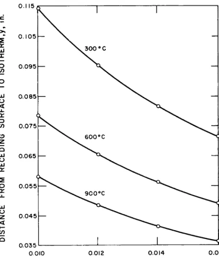
pend s on plasma p a r a m e t e r s, the separation being from about 0 . 0 25 to 0 . 0 30 in. when stagnation enthalpy is 10, 0 0 0 B t u / lb , and abou t 0. 12 in. when the enthalpy is 3400 B t u / l b. It is seen ( F i g. 9) that these enthalpies correspond to Type 1 ablation rates of 0 . 0 15 and 0 . 0 13 i n . / s ec > r e s p e c t i v e l y. That i s, the n e a r n e ss of the p u l s e - r e f l e c t i ng interface to the ablating end is i n v e r s e ly proportional to ablation r a t e.
A n i n v e r se relation probably corresponds to one or m o re relationships previously demonstrated for certain m a t e r i a l s, such as the distribution of temperature or density during a b›
lation. For e x a m p l e, let us consider the temperature d i s t r i› bution. Whe n the actual t e m p e r a t u re profile is adequately a p›
proximated by E q. ( 7 ), one can solve for y :
y(T) = ( l / s ) a l n ( Tw/ T) (15)
In E q. (15) it is stated that the distance from the ablating surface of, s a y, the 9 0 0 C i s o t h e r m, is i n v e r s e ly proportional to ablation r a t e. This idea is presented graphically ( F i g. 10), using values of a and Tw appropriate for ablating quartz.
Ultrasound, by affording a dynamic mean s of monitoring an elastic interface or corresponding isotherm or c h e m i c al boundar y during ablation, demonstrates one of its major a d›
vantages over static t e s ts p e r f o r m ed after ablation. T h u s, p o s t - t e st sectioning and subsequent study under high m a g n i f i› cation (3) ma y fail to show fully the relation between endotherm thicknesses and ablation r a t e.
Slightly Sophisticated E x p e r i m e n ts -- T e st Setup. In contrast to the relatively s i m p le initial e x p e r i m e n t s, a second s e r i es of experiments have been conducted to locate the elastic interface m o re p r e c i s e l y, and simultaneously to m e a s u re the temperature of this elastic i n t e r f a c e.
Th e experimental setup is shown below (Fig 11), and is nearly the s a me as presented e a r l i er ( F i g. 7 ). The modified
specimen is now notched, using ultrasonic equipmen t described in ( 2 7 ), in a plane perpendicular to its axis to provide an echo of know n origin during ablation. (In an alternate s p e c i m en design, a flat bottom plugged hole provides the echo of know n
1 6 5
SIXTH SYMPOSIUM ON BALLISTIC MISSILE AND AEROSPACE TECHNOLOGY
0 . 0 2 8
0 . 0 2 6 h -
0.012
STAGNATION ENTHALPY / 3 3 . 8 6
4 0 0
Fig. 9• M e a s u r ed Dependenc e of Ablation Rate on Stagnation Enthalpy for Three R e s i n - C e r a m ic C o m p o s i t e s.
166
ABLATION RATE, in. per sec
O.I 15
O . I 0 5 h-
0 . 0 9 5 r
0 . 0 8 5 h-
0 . 0 75
0 . 0 65 h -
0 . 0 5 5
0 . 0 45
0 . 0 35
0.010 0.012 0 . 0 14
A B L A T I ON R A T E, s , in per sec
0.016
Fig. 10. Location of I s o t h e r ms V e r s us Ablation Rate Whe n Temperatur e Distribution in Ablating Quartz is Given by Eq. (7).
167
DISTANCE FROM RECEDING SURFACE TO ISOTHERM,y, in.
SIXTH SYMPOSIUM ON BALLISTIC MISSILE AND AEROSPACE TECHNOLOGY
Fig. 11. Ultrasonic and Thermodynami c Equipmen t Used in Conjunction with P l a s ma A rc (Splash Test) F a c i l i t i e s.
168
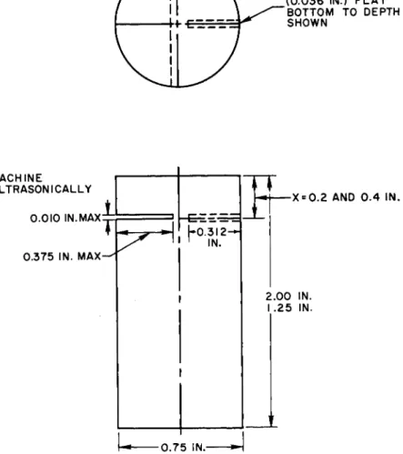
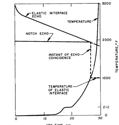
o r i g i n .) A radial hole has been drilled to accommodat e a platinum-platinum (90 percent) and rhodium (10 percent) t h e r- mocouple . The junction location should lie in the plane of that side of the notch from which the echo a r i s e s. (This condition can be verified radiographically, but a preferable installation u s es fluoroscopy while the thermocouple is being positioned. ) Notch and thermocouple positions are illustrated ( F i g. 12). Anticipated test r e s u l t s, o v e r s i m p l i f i ed to an extent dictated b y the scope of this presentation, a re illustrated ( F i g. 13). Extending these ideas ( F i g. 13), it ma y also be realized that plots of the t i me derivative of t e m p e r a t u r e, dT/dt , v e r s us t i m e, t , if properly coordinated with accurate r e c o r ds of specime n length s(t) , can be used to yield the distance between endotherm s and the ablating end. M o r e o v e r, the width of t h e r›
m a l a r r e s ts on this dT/dt v e r s us t plot can be interpreted as endotherm thickness divided by ablation rate s. To clarify the ablation mechanism details which have recently been extracted from t e m p e r a t u r e - t i me h i s t o r i e s, consider the following.
Th e t e m p e r a t u r e - t i me history recorded by a single t h e r› mocoupl e would coincide with the t e m p e r a t u re profile obtained if the ablation experiment w e re stopped at s o me instant after equilibrium (steady state) is a c h i e v e d, and the thermocouple wer e move d from the cool to hot end at a velocity equal to the ablation r a t e.
Whe n temperature is given by E q. ( 7 ), a plot of dT/dt v e r s us t ( m e a s u r ed at a fixed thermocouple location) should b e equivalent in shape to the result of differentiating E q. (7) with r e s p e ct to y :
i2_ = _ _ _ e- * y /« ( 1 6)
dy Æ
Tha t i s, plots of either dT/dt v e r s us t or dT/dy v e r s us y are exponential p r o f i l e s, when E q. (7) h o l d s. H o w e v e r , for the r e s i n - c e r a m ic composite Type 1, m e a s u r ed temperature p r o›
files are not smooth exponentials, but instead repeatedly show t h e r m a l a r r e s ts indicative of endothermic reactions occurring in thin reaction z o n e s. If the thermocouple were i d e a l, then in the dT/dt v e r s us t plot, endothermic t h e r m al a r r e s ts would b e manifested by t i me intervals At of z e ro temperature change.
In p r a c t i c e, t h e r m al a r r e s t s, or at least t h e r m al " r e t a r d s"
are presently identified by the marke d reduction in rate of temperature i n c r e a s e, the duration of this marke d reduction being At.
I 69
SIXTH SYMPOSIUM ON BALLISTIC MISSILE AND AEROSPACE TECHNOLOGY
M A C H I NE
U L T R A S O N IC A L LY ˇ.ˇ ˇ IN.MAX
0.375 IN. M AX
k0.3l2-H
1 IN. 1
- X = 0.2 A ND 0 .4 I N.
2.00 IN.
I .25 IN.
I
0.75 IN.-
Fig. 12. Notched P l a s ma A rc Specimen P e r m i ts Simultaneous Recording of Thermodynami c and Ultrasonic Data.
170
USE NO. 64 D R I LL _ ( 0 . 0 36 IN.) F L AT
B O T T OM TO D E P TH S H O WN
10 2 0 3 0 ARC T I M E , sec
Fig. 13. Simultaneous Recording of Ultrasonic and Thermodynami c Data Provides M e a s u r e m e n t of E l a s t ic Interface T e m p e r a t u r e.
1 7 1
TEMPERATURE,0 F
ECHO POSITION ON OSCILLOSCOPE
SIXTH SYMPOSIUM ON BALLISTIC MISSILE AND AEROSPACE TECHNOLOGY
Returning now to test setup d e t a i l s, an exploded view showin g a 1 m c ultrasonic t r a n s d u c e r, c o l l a r, and an i n s t r u› mented , notched specimen is given ( F i g. 14). Note that a concentric cylindrical shell insulates the thermocouple leads to prevent radial heating effects during the run. The d a r k e r, uninstrumented sample has a notch and hole 0. 2 in. from one end , while the lighter sample has a notch and hole 0 .4 in. b a c k.
In the a s s e m b ly photograph ( F i g. 15), the set s c r e ws permi t alinement and ensure tight acoustic coupling between transducer and s p e c i m e n.
Slightly Sophisticated Experiments -- O s c i l l o s c o pe Echo P a t t e r n s. Echo patterns, before (a) and during (b) ablation t e s t s, are shown ( F i g. 16). Referring to this f i g u r e, the need for a notched and instrumented specimen can be appreciated. A s ablation b e g i n s, surface t u r m o il quickly disrupts the end echo . An echo from the elastic interface a r i s e s, and eventual› ly overtakes the notch echo of know n origin. At the instant of echo coincidence, the elastic interface coincides with that s u r›
face of the notch c l o s e st to the t r a n s d u c e r. Knowledg e of specime n length v e r s us t i m e, from the profile r e c o r d, p e r m i ts easy calculation of the thickness between the elastic interface an d the ablating s u r f a c e.
Th e echo patterns ( F i g. 16) are somewha t i d e a l i z e d. F o r s m a l l - d i a m e t er specimens of highly-attenuating a b l a t i v e- type m a t e r i a l s, there is often not enough observable ultrasonic energy available to be divided between the notch and ablating end . In this c a s e, one can test pairs of s p e c i m e n s. One specime n should be notched, and the other unnotched. G r a p h › i c al superposition of test results gives the instant of echo coincidence.
G e n e r a l l y, the interpretation of o s c i l l o s c o pe patterns is accompanie d by a mode l for the m a t e r i al under t e s t. The patterns presented ( F i g. 16) correspond to a l o w - l o ss m o d e l.
Th e difference in ultrasonic r e s p o n se for l o w- and h i g h - l o ss model s is illustrated ( F i g. 17). F or the l o w - l o ss c a s e, both elastic interface and end echoes are detectable. For the h i g h- l o ss c a s e, the end echo (echo A ’) is o b s e r v a b l e, but the elastic interface echo (echo B1) is beneath the noise l e v e l.
Typ e 1 m a t e r i al has at least four subsurface elastic inter› faces (see F i g. 1). B e c a u se of the high attenuation, pulse f r e› quencies greater than 1 m c are ruled out. The pulse duration of 1 m c pulses is s e v e r al m i c r o s e c o n d s. Consequently, the
172
Fig. 14. Exploded View of T r a n s d u c e r, C o l l a r, an d Specimens.
1 7 5
SIXTH SYMPOSIUM ON BALLISTIC MISSILE AND AEROSPACE TECHNOLOGY
1 7 *
Fig. 15. Transducer A c o u s t i c a l ly Coupled to Instrumented Specimen.
(a) (b)
Fig. 16. Echo Patterns B e f o re (a) and During (b) Ablation T e s t s.
1 7 5
E L A S T IC I N T E R F A CE
U L T R A S O N IC R O U ND T R IP T I M E , / i s ec U L T R A S O N IC R O U ND
T R IP T I M E . ^ s ec S P E C I M EN
T R A N S D U C ER P L A S MA
E ND F C H D MAIN
BANG N O T C H ECHON^ MAIN
’ B A NG N O T CH E C H O>
SIXTH SYMPOSIUM ON BALLISTIC MISSILE AND AEROSPACE TECHNOLOGY
s
in
A = e- 0 . 2 8 7S B = 0 2 5 e -a 2 8 7S A.= e- 0.575S B ’ = 0 . 2 5 e "a 5 7 5S
0 1.0 0 . 25 1.0 0 . 25
1.9 0. 145 0 . 0 84
2.0 0 . 75 0.317
3.8 0 . 0 84 0 . 0 28
4.0 0.317 0.1
f
V = O.I in.//xsec- 2 .0
EN D
-ELASTI C INTERFAC E
* I - UJ Ο
=>
£
NOIS E LEVE L = 0 . 05Β Β
19 20 38 40 PULS E TRANSI T T I M E , , s e c - *-
3
NOIS E LEVE L - 0 . 05 ,Α' CL5 0 .
< I
0
Β*
Π J |
Β ' Α'I I
19 20
I I
38 40 PULS E TRANSI T TIME , μ sec •
Fig. 17. High Attenuation Buries Echo from E l a s t ic Interface Beneath N o i se L e v e l.
1 7 6
individual echoes from each elastic interface lose their i d e n›
tity. The resultant echo is a composite where the leading edge corresponds to the interface n e a r e st the t r a n s d u c e r, that is able to provide an echo above the noise l e v e l. The resultant echo has a shape that depends on the contributions from each i n t e r f a c e. T h u s, e x c e s s i ve attenuation ma y prevent all i n t e r› faces from being r e s o l v ed during a given t e s t.
Despite the difficulty of resolving i n t e r f a c e s, studies on Typ e 1 m a t e r i al have shown that the motion of the leading edge is often abrupt. This ultrasonic r e s p o n se can be explained by a molten silica layer ( F i g. 1) being blown away periodically whe n the vapor p r e s s u re (due to the p l a s t i c ’s decomposition products) beneath the viscous silica layer exceeds a threshold surface tension. Observations of the shape of the echo also suppor t this " c y c l ic blowing" aspect of ablation. H e n c e, both position and shape of the ultrasonic echo r e v e al an otherwise unobserved (to date) detail of the ablation m e c h a n i s m .
Th e motion picture c a m e ra ( F i g. 11) viewed the area seen ( F i g. 18). Ultrasonic pulse round trip t i me is m e a s u r ed along the o s c i l l o s c o pe t i me b a s e, while arc t i me is indicated by the stopwatch.
Slightly Sophisticated E x p e r i m e n ts -- Char Depth. I n t e r› pretation of the position and shape of an echo has been d i s c u s s ed above . Now we will conclude the d i s c u s s i on of ultrasonic r e›
sponse during ablation t e s ts by considering the change in a m p l i›
tude of an e c h o, due to the ablation m e c h a n i s m .
It has been shown (3) that the D -E interface is a s s o c i a t ed with a 100 C i s o t h e r m. This t e m p e r a t u re corresponds to the evolution of s t e a m. Now it is w e ll know n in the ultrasonic art that r e a r - s u r f a ce echoes can be dampe d by touching the r e›
flecting surface with a moistened finger. T r a n s f e r r i ng this experience to an ablative-type m a t e r i a l, we expect that steam will couple sound out of an i n t e r f a c e, thereby reducing the amoun t of sound reflected from that i n t e r f a c e.
E x p e r i m e n t a l l y, this expectation h^s been confirmed with specimen s of Type 1 m a t e r i a l. A 3 /8 in. diameter flat-bottomed hole is drilled a x i a l l y, to a depth of 0 .4 in. Next, a t i g h t-
fitting plug of Type 1 m a t e r i al is i n s e r t e d, filling the cavity. A n echo from the hole bottom is easily seen on an o s c i l l o s c o p e.
Durin g ablation t e s t s, the echo is found to drop suddenly in amplitude. At the time of the sudden drop, the distance from the hole bottom to the ablating surface is i n v e r s e ly proportional to ablation rate. F u r t h e r m o r e, temperature m e a s u r e m e n t s have shown that the drop in amplitude
1 7 7
SIXTH SYMPOSIUM ON BALLISTIC MISSILE AND AEROSPACE TECHNOLOGY
178
Fig. 18. Oscilloscope Measures r and Stopwatch Measures t.
o c c u rs at the momen t that the 100 C isotherm reaches the bottom of the h o l e. If the char depth is defined as the depth beneath the ablating surface at which the D -E interface r e›
s i d e s, then we conclude that ultrasound, in conjunction with other m e a s u r e m e n t s , proves that the char depth in Type 1 m a t e r i al is i n v e r s e ly proportional to ablation r a t e, for the range of ablation rates that have been studied.
A s limiting c a s e s, the char depth (if definable) mus t be z e ro when the ablation rate is infinite, and is limited only by specime n length, when the ablation rate is z e r o.
Futur e Experiments -- Ultrasonic I m p r o v e m e n t s . S p e c›
ime n and transducer d i a m e t e rs will be i n c r e a s e d, thereby promoting :
a. C l o s er simulation of r e - e n t ry vehicle g e o m e t r y.
(In a r e - e n t ry v e h i c l e, the beam will be relatively unbounde d in planes p a r a l l el to the h e a t - s h i e ld surfaces at the gage l o c a› tion. )
b . Focusing of ultrasound. (As the ratio of transducer (crystal) diameter to wavelength i n c r e a s e s, beam dispersion is r e d u c e d .)
c. M o r e energetic b e a m . (The ultrasonic energy t r a n s› f e r r ed from transducer to h e a t - s h i e ld m a t e r i al i n c r e a s es in proportion to the a r ea of the t r a n s d u c e r. )
Futur e E x p e r i m e n ts -- T h e r m o d y n a m i c I m p r o v e m e n t s . H e r e , efforts will be directed to improving the a c c u r a cy of measurin g the elastic interface temperature that would have existed at the instant of echo coincidence, if the thermocouple wer e absent. In this connection, the feasibility of installing subsurface v a p o r - d e p o s i t ed thermocouples will be r e v i e w e d.
In addition, the achievement of steady state-ablation will b e facilitated by feeding specimens into the p l a s m a, such that the ablating surface is nearly stationary in s p a c e.
Futur e Experiments -- Silhouette I m p r o v e m e n t s . C i n e›
radiography, in conjunction with i m a ge intensification, p r o m › i s es to i m p r o ve the a c c u r a cy of length m e a s u r e m e n t s s i g n i f i› cantly. F l a sh radiography ( 2 8, 29) also offers m e r it in this r e s p e c t. Both of these radiographic techniques r e c o rd interior dynamic s during ablation, permitting p o s t - t e st scrutiny.
Radiograph y r e c or ds cupping and angular ablation, and e l i m i› nates e r r o rs due to variations in index of refraction for light r a y s.
Incidentally, cineradiography and flash radiography are no t limited to monitoring the dynamics of splash t e s t s. Som e
1 7 9
SIXTH SYMPOSIUM ON BALLISTIC MISSILE AND AEROSPACE TECHNOLOGY
of the m o re obvious of the numerou s applications of radiography during turbulent-tube and shroud t e s ts include measuring inside diameter v e r s us t i m e, and observing char behavior: cracking, spalling, and eruption of v o l c a n o e s.
A n inexpensive mean s for recording X - r ay profiles is illustrated (Fig. 19). This rotary film transport will be i n›
corporated in future t e s t s.
Ultrasonic Resonance Techniques
Ultrasonic thickness gaging can be accomplished by mean s other than the p u l s e - e c ho technique. Ultrasonic resonance techniques are well established ( 1 1, 3 0, 3 1 ). The instrumenta›
tion usually c o n s i s ts of a tunable continuous wave system that indicates the loading of the transducer by the s a m p l e.
If velocity is independent of frequency in the m a t e r i al of unknow n t h i c k n e s s, then the thickness s is given by
wher e is v e l o c i t y, and ˜ is the frequency difference between tw o s u c c e s s i ve resonant h a r m o n i c s.
H o w e v e r , m o st ablative-type h e a t - s h i e ld m a t e r i a ls c o n›
tain plastics that exhibit velocity d i s p e r s i o n, and attenuation that i n c r e a s es exponentially as frequency is i n c r e a s e d. F or this c l a ss of m a t e r i a l s, thickness is m o re easily m e a s u r ed using the fundamental r e s o n a n c e:
(18)
wher e fj is the lowest resonant frequency and Aj is v/fj . Fo r illustrative p u r p o s e s, consider a h e a t - s h i e ld m a t e›
r i al 2 in. thick, that is expected to ablate down to 1 in. during r e - e n t r y. A s s u m e the sound velocity in the m a t e r i al is a constant, 0. 1 . / , for ultrasonic frequencies up to 1 m c . A t the onset of ablation, using E q. ( 1 7 ),
0.1 x 1 06 i n . / s ec < n qx f, (2 in.) = = 0.025 x 1 0b cps = 25 kc 11V )
1 2 χ 2 in.
180
(17)
After 1 in. has ablated,
0.1 χ 10 6 in./ sec
fid in.) =1 : = 50 kc (20)
2 χ 1 in. x
A t these low f r e q u e n c i e s, attenuation is muc h l e ss than at 1 m c . M o r e o v e r, wavelengths from 2 to 4 in. will hardly b e sensitive to surface r o u g h n e s s.
Reinforced p l a s t i cs and r e s i n - c e r a m ic composites a t›
tenuate ultrasound rapidly at room t e m p e r a t u r e, and m o re
rapidly during ablation. H e n c e, the resonant frequency will no t be s h a r p. If (2 in. ) is accurate to – 10 p e r c e n t, the u n›
certainty in thickness is – 0 .2 in. N o t e, however, that a c c u›
racy i m p r o v es as ablation p r o c e e d s. For i n s t a n c e, if (1 i n .) is accurate to – 10 percent, the uncertainity in thickness is reduced to – 0. 1 in. This simplified e r r or analysis does not consider the difference between resonant thickness and h e a t- shield t h i c k n e s s.
A note of caution should be injected h e r e. For the m a › jority of h e a t - s h i e ld m a t e r i a l s, it ma y be overly optimistic to expect resonant frequency resolution to within 10 percent.
Th e l a r g e r, heavier transducer n e c e s s a ry to resonate betwee n 25 and 50 kc constitutes another drawback to thickness
gaging of thick, highly attenuating heat shields by mean s of ultrasonic r e s o n a n c e.
It should be clear that deciding between an ultrasonic resonance system or an ultrasonic p u l s e - e c ho system depends on man y f a c t o r s, only two of which are acoustic r e s p o n se and h e a t - s h i e ld t h i c k n e s s.
Ultrasonic Identification of Ablation M a t e r i al
Muc h r e s e a r ch currently being directed at explaining the ablation mechanism involves costly determination of a multitude of m a t e r i a ls p r o p e r t i e s. Great expenditure of time and mone y is required to maintain t e st facilities and control test p a r a m › e t e r s.
Unfortunately, one of the t e st p a r a m e t e rs inadequately controlled is the identification of the s p e c i m en being t e s t e d.
In their haste for test data, investigators rush blocks of ne w m a t e r i a ls to the machine shop, trusting that their m a t e r i a ls
181
SIXTH SYMPOSIUM ON BALLISTIC MISSILE AND AEROSPACE TECHNOLOGY
F i g. 19. Inexpensive Mean s for Recording X - R ay P r o f i l e s.
182
are homogeneous , i s o t r o p i c, or at least uniform. T e st s p e c i› m e n s , a s s u m ed representative of the block or a region, are machine d from a r e as selected at random . An arbitrary n u m › be r is often attached to test specimens at this s t a g e, to d i s› tinguish a particular specimen completely from its neighbors. Group s of specimens are t e s t e d; that i s, subjected to various environments, and data are a v e r a g e d, smoothed, and a d v e r›
t i s e d. E r r or a n a l y s i s, being too t i m e - c o n s u m i n g, is forgotten. A m o re rational approach ma y start with the assumption that a m a t e r i al is a collection of defects. This is a true a s›
sumption , whereas the m o re c o m m o n assumption, that a m a › t e r i al is p e r f e c t, is f a l s e. Acceptable m a t e r i al ma y now be defined as m a t e r i al that contains a fortuitous or organized collection of d e f e c t s. Rejectable m a t e r i al contains an unfor›
tunate collection of d e f e c t s.
Whe n a new m a t e r i al is in its infancy, one cannot afford to be satisfied with c o l o r, s m e l l, or bulk density m e a s u r e m e n t s as c r i t e r ia of variability. Within a batch, and from batch to batch, m a t e r i a ls should be subjected to nondestructive s c r e e n›
ing tests selected from appropriate portions of the e l e c t r o m a g› netic and mechanical s p e c t r a. Correlation of nondestructive test results with destructive analyses will a c c e l e r a t e, not r e›
t a r d, m a t e r i al i m p r o v e m e n t , and will ensure a m o re reliable quality control p r o g r a m .
Ultrasonic r e s p o n se of m a t e r i a ls has been correlated at various t i m es with r e s i n - g l a ss r a t i o, p o r o s i t y, degree of cure of p l a s t i c s, c r a c k s, voids or i n c l u s i o n s, bond strength, tensile strength, and other defects or attributes ( 2 6 ). Ultrasound is bu t one of man y proven nondestructive techniques ( 1 0, 11). Whe n properly combined with other t e s t s, ultrasonic t e s ts provide v e r s a t i l i ty with which m a t e r i a ls p r o b l e ms can be rationally approached and m o re gracefully surmounted.
Conclusions
Whe n used in conjunction with other m e a s u r e m e n t s , u l›
trasonic r e s p o n se during ablation t e s ts can be interpreted to r e v e al elusive details of the ablation mechanism that ma y o t h e r› wise remain undetected. Char depth, rupture of the ablating
surface by expanding g a s e s, and the degree to which steady state is achieved have been o b s e r v ed u l t r a s o n i c a l l y.
Accurate determination of ablation rate is of interest both a c a d e m i c a l ly and for design p u r p o s e s. Although the
18J