DOI: 10.1556/606.2018.13.3.10 Vol. 13, No. 3, pp. 95–106 (2018) www.akademiai.com
NUMERICAL EXAMINATION OF NONLINEAR OSCILLATORS
Flóra HAJDU
Department of Mechatronics and Machine Design, Faculty of Mechanical Engineering, Informatics and Electrical Engineering, Széchenyi István University
Egyetem tér 1. H-9026 Győr, Hungary, e-mail: hajdfl@sze.hu Received 21 December 2017; accepted 22 April 2018
Abstract: The numerical examination of nonlinear oscillators is presented in this paper. First some methods of nonlinear system modeling are described then the numerical creation of phase- plane, bifurcation diagrams and Poincaré sections are expounded in detail. The next part of the paper is the numerical examination of nonlinear oscillators, like the Duffing-Holmes oscillator and a mechatronic semi-active suspension system. The paper concludes with further development tasks.
Keywords: Nonlinear oscillator, Numerical simulation, System modeling
1. Introduction
Due to the development of computer science, numerical methods can be used to examine complex nonlinear systems quickly and accurately. It has also become possible to study phenomena that could not be investigated earlier [1]-[4].
Nonlinear vibrations occur in countless areas, like vehicle dynamics [5], transportation [6], machine tools [7] or electrical devices [8]. With simple nonlinear oscillators, like the Van der Pol oscillators complex systems and phenomena [9]-[13]
have already been modeled. In this paper nonlinear oscillators are examined with numerical methods. First the examination methods of nonlinear systems are summarized then the numerical methods are described in detail. The next part of the paper is the numerical examination of a simple nonlinear oscillator, the Duffing-Holmes oscillator and a mechatronic semi-active suspension system. The paper concludes with further development tasks.
To study nonlinear systems there are numerical, graphical (Cobweb plot [14]) and analytical methods (determination of the eigenvalues of the Jacobian determinant after linearization [15], perturbation methods [16]). With perturbation methods the approximate analytical solution of the Van der Pol oscillator and the Duffing-Holmes oscillator has already been determined [17]. As numerical simulations are very common nowadays in engineering numerical examination methods have been chosen for our research. Maple was used as it is a powerful tool for both symbolic [18], [19], and numerical [20], [21] calculations.
To study nonlinear dynamical systems one of the most effective method is the numerical creation of phase-plane diagrams, which shows 2 state variables and their trajectories in a diagram. Previously simple nonlinear systems like a tunnel diode circuit have been investigated with detailed phase-plane diagrams. With detailed phase-plane diagrams it was observed how the change in a system parameter affects the boundary line of sets of attraction [22]. This information can be useful to design a switching circuit. A trajectory in a phase-plane can be easily calculated. After solving the system of equations with a numerical solver the diagram of two system variables can be displayed. The numerical creation of phase-plane diagram of simple nonlinear systems has been speedup with a SIMD model based parallel algorithm [23].
For complex nonlinear systems the phase-space diagram can be difficult to study, especially in case of chaotic nonlinear oscillators. To simplify the examination Poincaré sections (Fig. 1 left) can be created. Poincaré section is the cross-section of a trajectory with a plane in the state-space [24]. Therefore Poincaré section is suitable to study systems with at least 3 state variables, but with a simple modification Poincaré section of systems with 2 variables can be created. The system of equations can be expanded with an additional variable, which is the angular velocity. Then the Poincaré section can be created in a way that the trajectory intersects a plane in a torus, which happens at every time period (Fig. 1 right) [20]. In numerical simulations this means that the result is calculated at every period time.
Fig. 1. Creation of the Poincaré section (Chua’s circuit) (left) and expanding the 2 dimensional system to 3 dimensions (right) [19]
The bifurcation diagram shows the change in the topology of the system as the bifurcation parameter is varied [25]. It is especially useful for studying nonlinear oscillators as it shows when the system’s behavior is chaotic [26].
The bifurcation diagram of a tunnel diode circuit was previously created [27]. From the bifurcation diagram the number of equilibrium points could be determined as a
bifurcation parameter (e.g. resistance) was changed. As it is a simple nonlinear system Maple’s implicitplot command was sufficient. However to construct the bifurcation diagram of nonlinear oscillators is more difficult. A fast and efficient iterative program described in [20] can be used (Fig. 2). The bifurcation diagram can be created with another iterative method based on Poincaré sections [20].
Fig. 2. Flow chart of creating the bifurcation diagram
The equivalent of the bifurcation diagram in the frequency domain is the frequency spectrum map, which represent the change of the frequency components, when a parameter is varied [28].
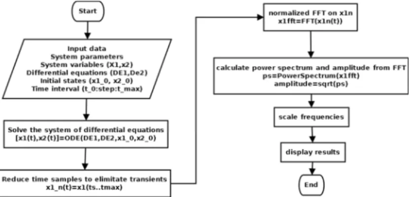
3D frequency response maps can be created if 2D frequency response diagrams are calculated at different parameter values. To create the frequency response diagram at a certain system parameter the time diagram is taken. At the time diagram normalized Fast Fourier Transform (FFT) was used [29]. From the transformed data the spectrum can be calculated. To get the amplitude values the spectrum data is square rooted. The values were scaled according to the sampling frequency [30], which was the time step of the numerical solution in this study. In this study the sampling frequency was 100 Hz and there were 213 samples. The flow chart to create the frequency diagram can be seen in Fig. 3.
Fig. 3. Flow chart of creating the frequency diagram
An effective method to study the systems stability is to determine its Lyapunov functions and exponents [31]. If a system has a Laypunov exponent t>0 there will be a chaotic attractor. The greater the value of the Laypunov exponent the more complex the attractor is [24]. It can be used for example to determine the stability of a cutting process, which is essential for manufacturing [32]. Lyapunov exponents can also be used to study the stability of human standing balance ability [33], which is useful information for example to design a walking aid device.
2. Numerical examination of nonlinear oscillators
In this section nonlinear oscillators are examined with the previously presented methods. First a simple Duffing-Holmes oscillator found in the literature, and then a semi-active suspension system of a car is studied.
2.1. Duffing-Holmes oscillator
The Duffing-Holmes oscillator is a well-known simple nonlinear system. The equation of the system is:
) cos(
) ( ) ( ) ( )
( 3
2 2
t t
x t x t dt x t d x dt
d +δ +β +α =γ ω . (1)
From the differential equation it can be seen that there are several system parameters. The initial parameters are chosen to get a chaotic behavior. The aim of this study was to test the presented numerical methods with a known example and to examine some possibilities to avoid chaotic behavior. The initial parameters therefore were α=1, β= -1, γ=0.3, ω=1 and δ=0.15. The initial states were x(0)=1 and dx(0)=0.
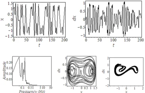
Chaotic behavior can be observed in Fig 4:
• in the time diagrams the waveform is different in every period time and the period time varies;
• in the frequency response diagram there are several components and continuous parts;
• in the phase-plane diagram the trajectory (limit cycle) is not steady;
• there is a chaotic attractor at the Poincaré section. This attractor can be further examined with defining its fractal dimensions [24].
Chaotic oscillation can be harmful [34], it is advisable to avoid it. Therefore some numerial experiments are carried out to examine some possibilities to avoid chaotic behavior.
To examine the behavior of the system with γ=0.3 the bifurcation diagrams with varying ω and δ are created, which can be seen in Fig. 5.
From Fig. 5 left it can be stated, that when δ is very small (<0.01) or 0.17<δ<0.4 there is chaotic oscillation and when 0.01<δ<0.17 or 0.4<δ then there is harmonic or subharmonic oscillation. In Fig. 5 right it can be seen that changing ω results in
harmonic oscillation or stable limit cycle in most cases, chaos only occurs, when 0.5<ω<1.5.
Fig. 4. Time diagrams (up), frequency diagram (below left), phase plane diagram (below middle) and Poincaré section (below right) of the Duffing-Holmes oscillator in case of chaotic behavior
(α=1, β= -1, γ=0.3, ω=1 and δ=0.15)
Fig. 5. Bifurcation diagrams of the Duffing-Holmes oscillator
In linear case it is easy to define the harmful resonance frequency [35]. Resonance does not occur if the forcing frequency is different from the resonance frequency.
Similarly in nonlinear case the chaotic oscillation can be avioded if the forcing frequency can be changed as it can be seen in the bifurcation diagram (Fig. 5 right).
Numerical tests were carried out with ω=3. The time diagrams, the phase-plane diagram and the Poincaré section are shown in Fig. 6.
Fig. 6. Time diagrams (up), phase plane diagram (below left) and Poincaré section (below right) of the Duffing-Holmes oscillator in case of ω=3 (α=1, β= -1, γ=0.3, and δ=0.15)
It can be seen that in the phase-plane diagram there is a circle and in the Poincaré section there is only a single point. These are the signs of a harmonic oscillation.
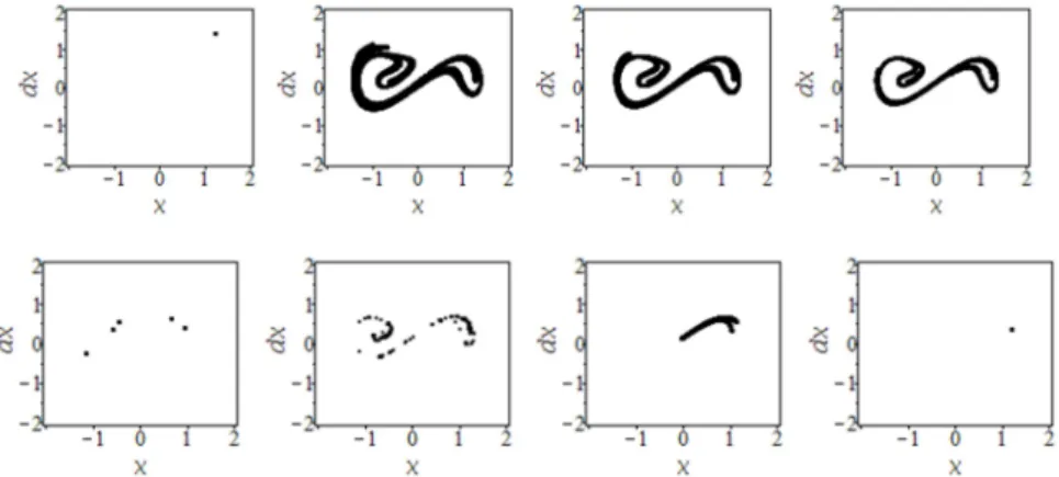
As the frequency of the external force can not be modified in an easy way it is useful to change an other system parameter (e.g. damping δ). In Fig. 7 the change in the Poincaré section can be seen as parameter δ is modified from 0.1 to 0.45. It was examined how change in parameter affects the chaotic attractor.
Fig. 7. Change in the Poincaré section as parameter δ is varied (δ=0.1···0.45)
It can be seen that first there is harmonic oscillation, and then there is a chaotic attractor, which shape will be smaller as parameter δ is increased. When δ=0.3 a subharmonic oscillation occurs, then there will be chaos again. When δ=0.5 harmonic oscillation or a stable limit cycle occurs. With this test it was examined that with changing a system parameter the chaotic region can be avoided or another chaotic attractor can be achieved, which is easier to control. Possibilities of controlling chaos will be further research task.
2.2. Numerical examination of a Duffing type mechatronic semi-active suspension system
Duffing-Holmes oscillator is a forced oscillator with a nonlinear spring, whose restoring force is Fs =−β −x αx3, [36]. Several simple mechatronic devices have already been developed to examine the phenomena described by the Duffing-Holmes equation. Most of them are elastic mass vibrating in the magnetic field, like elastic beam [37], mass on a wire [38] or magnetic mass on a spring [39]. The Duffing-Holmes equation has already been used in real mechatronic systems, such as designing an electromagnetic generator [40] or modeling a semi-active suspension system [41].
In this study a semi-active suspension system with magneto-rheological damper of a vehicle is examined (quarter car model). It is assumed, that the spring has a nonlinear restoring force mentioned before and the damping is assumed to be constant.
The differential equation can be written:
) cos(
) ( 1000 ) ( ) ( )
( 3
2 2
t A t mx t c
mx t c dt x
d m t k x dt
d + − + = ω (2)
where m is the mass of the vehicle; k is the damping coefficient; c is the spring stiffness;
A is the amplitude of the road profile and ω is the angular velocity of the external force, which depends on the velocity of the vehicle and the wavelength of the road [42].
Parameters k=35000 and m and c were varied. The road profile is assumed to be sinusoidal with A=0.2 and ω=2π.
It was examined how the change in mass and damping constant affects the behavior of the vehicle. The initial value are c=1000 and m=375 (based on [43]). The bifurcation diagrams can be seen in Fig. 8.
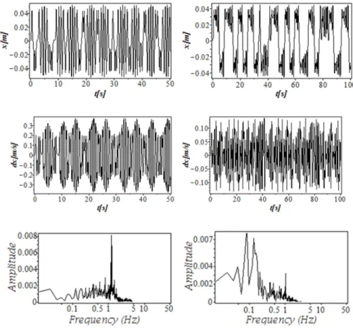
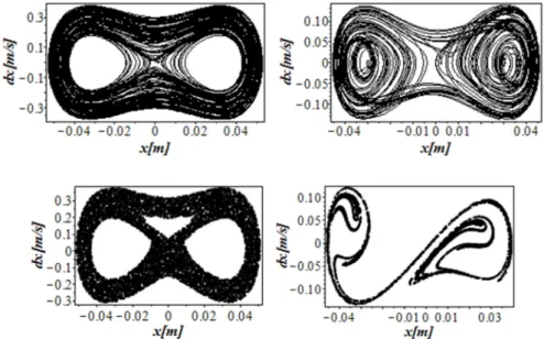
It can be seen that there is a chaotic behavior if the damping coefficient c≈0, which means a failure in the damper. If m>1000 there is also a chaotic behavior, which can be caused by increased load on the axle. The results for the chaotic behavior can be seen in Fig. 9 and Fig. 10 (c=0 left and m=1050 right).
Chaos can be observed in both cases. On the Poincaré sections there are 2 different chaotic attractors. In the first case (c=0) there is a main frequency component and several smaller amplitude frequency components. In the second case (m=1050) there are 2 main frequency components and several smaller amplitude frequency components.
There are continuous parts in the frequency diagrams, which is also a sign of chaotic behavior.
Fig. 8. Bifurcation diagrams of a semi-active suspension system
Fig. 9. Time diagrams and frequency diagrams of a semi-active suspension system left (c=0, right m=1050 )
With this test it was showed that the described methods can be used effectively to study chaotic behavior in case of nonlinear mechatronic systems too. It was also observed, that chaos can occur in real systems. In this case there was chaos in extreme
conditions (e.g. failure in the damper). Next task of the research is to study other cases, when chaotic behavior can occur (e.g. effects of road profile).
Fig. 10. Phase plane diagrams and Poincaré sections of a semi-active suspension system left (c=0, right m=1050 )
3. Conclusion and further development
In this paper nonliear oscillators, like the Duffing-Holmes oscillator and a semi- active suspension system were examined with numerical methods. Phase-plane diagrams, time diagrams, frequency response diagrams and Poincaré sections were created. It was observed when chaotic oscillation can occur. Some tests were carried out to examine how to avoid chaotic behavior. This study will be continued with examining the possibilities of controling chaos. Besides there are several research tasks.
The creation of numerical diagrams can be very time consuming, so one of the most important task is parallelization. With parallelization it will be possible to create diagrams with large calculation time, like 2 parametric bifurcation diagrams and frequency spectrum maps fast. Other tasks are to expand the presented methods to systems with more variables, like the Chua’s circuit or Lorentz attractor and to examine the sensitivity to initial conditions. A measure equipment will also be developed in the future to examine nonlinear vibratios in real mechatronic systems. Main goal is to examine more difficult nonlinear especially mechatronic systems with the presented methods.
Acknowledgements
This study was supported by the ÚNKP-17-3 New National Excellence Program of the Ministry of Human Capacities
References
[1] Fülep D., Zsoldos I., Lászó I. Self-organised formation of nanotubes from graphene ribbons: A molecular dynamics study, Materials Research Express, Vol. 3, No. 10, 2016, paper 5044.
[2] Zhang K., Wu Y. S., Bodvarsson G.S. Parallel computing simulation of fluid flow in the unsaturated zone of Yucca Mountain, Nevada, Journal of Contaminant Hydrology, Vol. 62–63, 2003, pp. 381–399.
[3] Krejci T., Kruis J., Koudelka T. Sejnoha M. Processor farming in two-level analysis of historical bridge, Proceedings of the Fifth International Conference on Parallel, Distributed, Grid and Cloud Computing for Engineering, Pécs, Hungary, 30-31 May 2017, Civil-Comp Press, Stirlingshire, UK, 2017, Paper 12.
[4] Strofylas G. A., Porfyri K. N., Nikolos I. K., Delis A. I., Papageorgiou M. Calibrating a traffic flow model with parallel differential evolution, Proceedings of the Fifth International Conference on Parallel, Distributed, Grid and Cloud Computing for Engineering, Pécs, Hungary, 30-31 May 2017, Civil-Comp Press, Stirlingshire, UK, Paper 26.
[5] Takács D., Stépán G. Contact patch memory of tyres leading to lateral vibrations of four- wheeled vehicles, Philosophical Transactions of the Royal Society A, Mathematical Physical and Engineering Sciences, Vol. 371, No. 1993, 2013, Paper 20120427, p. 12.
[6] Pidl R. Consideration on road transport vibration simulation techniques for packaging testing purposes, Acta Technica Jaurinensis, Vol 10. No. 2, 2017, pp. 137–147.
[7] Stépán G. Delay-differential equation models for machine tool chatter, Dynamics and Chaos in Manufacturing Processes, Vol. 471152935, 1998, pp. 165-192.
[8] Schiffer A, Ivanyi A. Vibration of transformer sheets using non-linear characteristics, Journal of Physics, Conference Series, Vol. 268:, 2011, paper 012027.
[9] Peluffo-Ordonez D. H., Rodríguez-Sotelo J. L., Revelo-Fuelagán E. J., Ospina-Aguirre C., Olivard-Tost G. Generalized Bonhoeffer-van der Pol oscillator for modeling cardiac pulse:
Preliminary results, 2015 IEEE 2nd Colombian Conference on Automatic Control, Manizales, Colombia, 14-16 October 2015, DOI: 10.1109/CCAC.2015.7345211
[10] Facchinetti M. L., Langre E., Biolley F. Vortex shedding modeling using diffusive van der Pol oscillators, Comptes Rendus Mécanique, Vol. 330, No 7, 2002, pp. 451–456.
[11] Dumitrescu I., Bachir S., Cordeau D., Paillot J. M., Iordache M. Modeling and characterization of oscillator circuits by Van Der Pol model using parameter estimation, Journal of Circuits, Systems, and Computers, Vol. 21. No. 5. 2012, paper 1250043.
[12] Chian A. C. L. Complex systems approach to economic dynamics, Springer-Verlag, Berlin Heidelberg, 2007.
[13] Wang L. Reliable design of tunnel diode and resonant tunnelling diode based microwave sources, PhD Thesis, University of Glasgow, 2012.
[14] Garay B. Nonlinear dynamical systems (in Hungarian), Pázmány Péter Catholic University, 2013, http://www.tankonyvtar.hu/en/tartalom/tamop412A/2011-0052_20_nemlinearis_
dinamikus_rendszerek/index.html (last visited 12 November 2017).
[15] Khalil H. K. Nonlinear systems, Prentice Hall, 1999.
[16] Bayat M., Pakar I. On the approximate analytical solution to non-linear oscillation systems, Shock and Vibration, Vol. 20, No. 1, 2013, pp. 43–52.
[17] Abdelhafez H. M. Solution of excited non-linear oscillators under damping effects using the modified differential transform method, Mathematics, Vol. 4, No. 1. 2016, p. 12.
[18] Maróti Gy. Investigating parameterized model of n-gonal wheel’s motion, Pollack Periodica, Vol. 6, No. 2, 2011, pp. 25‒36.
[19] Maróti Gy. Finding closed-form solutions of beam vibration, Pollack Periodica, Vol. 6, No. 1, 2011, pp. 141‒154.
[20] Lynch S. Dynamical systems with applications using maple, Birkhäuser Boston, 2010.
[21] Perjési-Hámori I. Two dimensional mathematical model of heat-transmission using MAPLE, IFAC-PapersOnLine, Vol. 48, No. 1, 2015 pp. 689–690.
[22] Hajdu F. Numerical examination of a nonlinear circuit element (in Hungarian), Proceedings of the 5th Interdisciplinary Doctoral Conference Conference, Pécs, Hungary, 27-29 May 2016, pp. 142–154.
[23] Hajdu F., Molnárka Gy. Parallelization of numerical examination of nonlinear systems using Maple, Proceedings of the Fifth International Conference on Parallel, Distributed, Grid and Cloud Computing for Engineering, Pécs, Hungary, 30-31 May 2017, Civil-Comp Press, Stirlingshire, UK, Paper 30.
[24] Aguierre L. A. A tutorial introduction to nonlinear dynamics and chaos, Part 1, Tools and benchmarks, SBA Controle & Automacao, Vol. 7, No. 1, 1996, pp. 29–49.
[25] Kuznetsov Y. A. Elements of applied bifurcation theory, Springer, 1998.
[26] Garay B. M., Indig B. Chaos in Vallis’ asymmetric Lorenz model for El Niño, Chaos, Solitons & Fractals, Vol. 75, 2015, pp. 253‒262.
[27] Hajdu F., Molnárka Gy. Numerical examination of a system model with a nonlinear component, Proceedings of the 8th International Scientific and Expert Conference, Trnava, Slovakia, 19-21 October 2016, pp. 12‒16.
[28] Billings S. A., Boaghe O. M. The response spectrum map, a frequency domain equivalent to the bifurcation diagram, International Journal of Bifurcation and Chaos, Vol. 11, No. 7, 2001, pp. 1961–1975.
[29] Kuczmann M. Fourier transform and controlling of flux in scalar hysteresis measurement, Physica B: Condensed Matter, Vol. 403 No.2-3, 2008 pp. 410‒413.
[30] Maple soft: new features in Maple 17, Signal processing, https://www.maplesoft.com/
products/maple/new_features/maple17/signal_processing.aspx, (last visited 1 October 2017).
[31] Sári Z. Investigation of multi-valued, hysteresis-type nonlinearities in numerical field problems, PhD Thesis, Budapest University of Technology and Economics, 2012.
[32] Sykora H. T., Wedig W. V., Bachrathy D., Stépán G. Approximation of top Lyapunov exponent of stochastic delayed turning model using Fokker-Planck approach, Proceedings of the 9th European Nonlinear Dynamics Conference, Budapest, Hungary, 25-30 June 2017, Paper 429
[33] Liu K., Wang H., Xiao J., Taha Z. Analysis of human standing balance by largest Lyapunov exponent, Computational Intelligence and Neuroscience, 2015, Paper 158478.
[34] Ivancevic V. G., Ivancevic T. High-dimensional chaotic and attractor systems, Springer Netherlands, 2007.
[35] Égert J., Jezsó K. Mechanics-vibrations (in Hungarian), Széchenyi István University, Győr, Hungary, 2006.
[36] Takashi K. Duffing oscillator, Scholarpedia, http://www.scholarpedia.org/article/
Duffing_oscillator (last visited: 26.03.2018).
[37] Tam J. I., Holmes P. Revisiting a magneto-elastic strange attractor, Journal of Sound and Vibration, Vol. 333, No. 6, 2014, pp. 1767‒1780.
[38] Mojrzisch S., Wallaschek J., Bremer J. An experimental method for the phase controlled frequency response measurement of nonlinear vibration systems, Proceedings in Applied Mathematics and Mechanics, Vol. 12, No. 1, 2012, pp. 253‒254.
[39] Donoso G., Ladera C. L. Nonlinear dynamics of a magnetically driven Duffing-type spring–magnet oscillator in the static magnetic field of a coil, European Journal of Physics, Vol. 33, No. 6, 2012, pp. 1473‒1486.
[40] Cottone F., Basset P., Vocca H., Gammaitoni L. Electromagnetic buckled beam oscillator for enhanced vibration energy harvesting, IEEE International Conference on Green Computing and Communications, Besancon, France, 20-23 November 2012, doi:
10.1109/GreenCom.2012.151.
[41] Litak G., Borowiec M., Friswell M. I., Szabelski K. Chaotic vibration of a quarter-car model excited by the road surface profile, Communications in Nonlinear Science and Numerical Simulation, Vol. 13, No. 7, 2008, pp. 1373‒1383.
[42] Barbosa R. S. Vehicle dynamic response due to pavement roughness, Journal of the Brazilian Society of Mechanical Sciences and Engineering, Vol. 33, No. 3, 2011, doi:
10.1590/S1678-58782011000300005
[43] Fakhraei J., Khanlo H. M., Ghayour M. Chaotic behaviors of a ground vehicle oscillating system with passengers, Scientia Iranica, Vol. 24, No. 3, 2017, pp. 1051‒1068.
![Fig. 1. Creation of the Poincaré section (Chua’s circuit) (left) and expanding the 2 dimensional system to 3 dimensions (right) [19]](https://thumb-eu.123doks.com/thumbv2/9dokorg/1398053.116832/2.892.228.738.696.828/creation-poincaré-section-chua-circuit-expanding-dimensional-dimensions.webp)