THE TRUNK MODEL: A MULTI-SEGMENT APPROACH OF THE THORAX
Gábor Grósz, Beatrix Lauter, Gerlinde Lenaerts, Dóra Pákozdi, Katalin Vámos, Sándor Kiss, György Szőke, Tamás Terebessy
Department of Orthopaedics, Semmelweis University grgt85@gmail.com
Abstract
3D motion anlysis is a tool for evaluating gait and posture parameters in orthopaedic deformities.
Spinal desorders are very common in paediatric orthopaedic practice. Recently used motion capture methods are not suitable for modeling the kinematics of the trunk segments. The aim of this study was to develop a kinematic model for the trunk that could be applied to measure segmental motions. In the present model the trunk was divided into three parts: the upper thorax, the lower thorax and the pelvis. 13 healthy volunteers were measured to calculate standard graphs for the segmental movements of the trunk. The distance of the C7-Th10 vertebrea, the sagittal- and frontal plane balance and the intersegmental rotation were evaluated. Results of this study present normative values of the trunk motion and highlight the flexibility of the thorax. Our trunk model provide possibility for segmental modeling the trunk in adolescence posture desorders such as scoliosis, Scheuermann’s kyphosis and also in adult spinal diseases.
Keywords: Multi-segment model, Thorax, Gait Analysis, Scoliosis, Scheuermann’s disease
1. Introduction
Scoliosis and Scheuermann’s disease are the most frequent orthopaedic deformities in the adolescence. The overall prevalence of scoliosis with curvature of more than 10° is 1.2% (3.5 times more frequent in girls), moreover the prevalence of curves exceeding 20° is 0.5%.1 The frequency of Scheuermann’s kyphosis is rather difficult to estimate, since different authors use variable criteria for the diagnosis. The prevalence varies from 3-8%.2-3 Due to these two conditions thousands of teenagers need therapy. In both diseases the vertebral column is deformed, the shape and functions of the spine are altered.
Evaluation the rigidity of the deformed thoracic spine has utmost importance both for physiotherapy and for brace treatment. In the everyday clinical practice only manual methods exist to estimate the mobility of the thoracic spine. Functional X-ray tests are usually used to assess the possibility of correction only for planning surgery.4
Neither motion capture methods are suitable for assessing the 3D flexibility of the vertebral column for conservative therapy, because the commonly used gait models demonstrate the trunk as a single rigid body without any internal movements. The aim of our current study was to plan and develop a motion capture model which is able to describe the basic functional parameters of the spine during gait and to get information about the tilting and rotation movements of the upper part of the thorax compared to the lower part of the thorax.
2. Methods
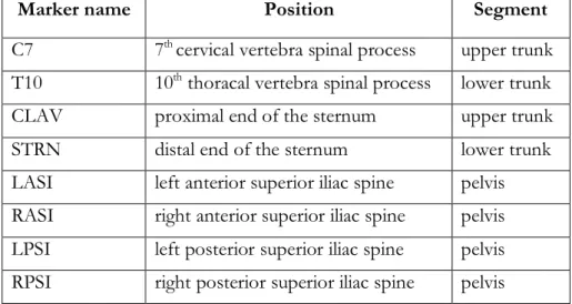
Eleven healthy volunteers (mean age 24±3.6 years) were examined in the Gait Lab of Semmelweis University. Vicon PlugInGait FullBody model 5 was used for observing the range of motion of the lower limb joints. The trunk is represented as a single rigid body in the Vicon model. In our experimental setup the trunk was divided into three parts: the upper thorax, the lower thorax and the pelvis. The markers which were used for the model are shown in Table 1.
Marker placement defines three axes. The C7 and CLAV markers for the axis of the upper thorax, the T10 and STRN markers for the axis of the lower thorax and the LASI, RASI, LPSI and RPSI markers for the sagittal midline axis of the pelvis. A simple axis allows assessing two dimensional movements. Therefore only tilting- and rotation of the segments can be measured.
Tilting was determined as sagittal plane movements of the upper thorax to the lower thorax named on the trunk model as UPtoLOW tilt, movements of the upper thorax to the pelvis named on the trunk model as UptoPELV tilt, and movements of the lower thorax to the pelvis named on the trunk model as LOWtoPELV tilt. Similarly, rotation was determined as horizontal plane movements of the upper thorax to the lower thorax-, the upper thorax to the pelvis and the lower thorax to the pelvis and named on the trunk model as UPtoLOW rotation, UptoPELV rotation and LOWtoPELV rotation respectively. Although lateral bending movements are undetectable in this model, the benefit of this simple marker placement gives the possibility to use the model in corset wearing as well.
Marker name Position Segment
C7 7th cervical vertebra spinal process upper trunk T10 10th thoracal vertebra spinal process lower trunk CLAV proximal end of the sternum upper trunk
STRN distal end of the sternum lower trunk
LASI left anterior superior iliac spine pelvis RASI right anterior superior iliac spine pelvis LPSI left posterior superior iliac spine pelvis RPSI right posterior superior iliac spine pelvis
Table 1. Names and position of markers used in the trunk model
2.1 Upper thorax
2.1.1 Anatomical definition
The upper part of the thorax is modelled with the axis defined by the segment between C7 and CLAV markers. The C7 marker is placed over the spinal process of the 7th cervical vertebra and the CLAV marker is placed over the jugular notch. The rigidity of this thoracic part is ensured by
2.1.2 Technical frame
Axis 1 is from C7 to CLAV. A horizontal supporting vector was set perpendicular to axis 1. Axis 2 is perpendicular to axis 1 and to the supporting vector.
2.2 Lower thorax
2.2.1 Anatomical definition
The Vicon FullBody model uses markers on the spinal process of the 10th thoracic vertebra and also on the xiphoid process of the sternum. The segment defined by these two markers assumed to move as a rigid body since the 10th pair of ribs provides bony connection between the two markers.
2.2.2. Technical frame
Axis 1 is from T10 to STRN. A horizontal supporting vector was set perpendicular to axis 1. Axis 2 is perpendicular to axis 1 and to the supporting vector.
2.3 Pelvis
2.3.1 Anatomical definition
In conventional gait models the pelvis is usually demonstrated with markers on the iliac bones and on the sacrum.6, 7, 8 We use markers placed over the anterior superior iliac spines and over the posterior superior iliac spines. Although the four markers would allow the 3D modelling of the pelvic movements, in our trunk model only the sagittal midline vector of the pelvis was considered.
2.3.2 Technical frame
The sagittal midline vector of the pelvis was determined with the help of two virtual markers: one in the midpoint of LASI and RASI, named SILS, and one between LPSI and RPSI named SACR.
The line defined by the two virtual markers is axis 1. A horizontal supporting vector was set perpendicular to axis 1. Axis 2 is perpendicular to axis 1 and to the supporting vector.
2.4 Additional calculations
The perpendicular line to a vector in the horizontal plane is calculated by swapping the first and second coordinate and multiplying one of them by (-1). The third coordinate is 0 or a constant due to being parallel to the ground.
The model calculates the frontal- and sagittal balance of the spine too. The frontal balance describes the distance of the C7 marker from the virtual SACR marker on the horizontal line (frontal plane balance or clinically called decompensation)9 The sagittal balance means the distance of the C7 marker from the virtual SACR marker on the sagittal line (sagittal balance).10 The distance between the C7 and Th10 markers was measured as well. The distance can model the upright position of thoracic spine, however aiming the inter subject comparability the parameter has to be normalised by the body height.
On the rotation graphs and also on the horizontal balance graphs the kinematic curves produced during the left step are presented in real values, however to ease the interpretation, the kinematic curves produced during the right step were multiplied by (-1) to allow the curves to run parallel.
3. Results
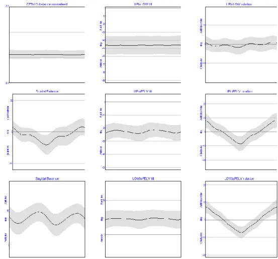
Figure 1. Averaged trunk segment angles and parameters from 11 healthy volunteers
A preliminary study has been carried out on the reliability on a model calculating the deformities of the trunk and movement of the spine during level walking. Based on the results of the eleven
Figure 2. Normalised distance of the C7 and Th10 vertebra
The distance of the 7th cervical- and the 10th thoracic vertebra is a proper parameter to quantify the curvature of the spine, and is normalised by the height of the subject. Normalisation is necessary to compare the patients with different body height. Based on the results of the healthy volunteers the value of 0.156±0,009 is considered normal.
Figure 3. Frontal and sagittal balance of the spine
The frontal plane balance is oscillating with 1.5 cm amplitude around 5 mm decompensational offset. The peaks occur in midstance and in terminal swing. The offset can be explained by the
natural right convex curve of the spine. The sagittal balance can be described by a double bump shaped curve. The peeks occur in midstance and midswing. On the curve an average of 40 mm anterior imbalance is seen. The explanation for this phenomenon is that the sagittal balance was calculated with the distance of the C7 marker from the virtual SACR marker on the sagittal line, however sagittal balance means when C7 plumb line intersects the body of the first sacral vertebra. The virtual SACR marker is 3-5 cm posterior to the body of the first sacral vertebra.
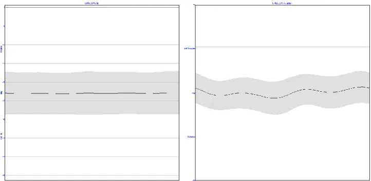
Figure 4. Upper trunk motion compared to lower trunk
As shown in Figure 4. the upper trunk movements compared to the lower trunk are minimal. An almost constant UptoLOW tilt can be observed and only a minimal clockwise rotation was measured in the upper trunk with respect to the lower trunk. The range of tilt is reduced to a value of less than 1° around 46°±11,5, while the range of rotation is less than 2.5°. These observations are in good concordance with our expectations since the mild anticlockwise rotation of the lower trunk is caused by the physiological scoliosis of the healthy volunteers.
The motion of the upper and lower trunk compared to the pelvis is presented in Figure 5. The connection between the trunk segments and the pelvis is more flexible. The increased ROM is especially prominent in the coronal plane. UPtoPELV tilt and LOWtoPELV tilt show a double bump shaped curve with the peeks at loading response phase and at initial swing phase. Since initial swing phase corresponds with the loading response phase of the contralateral limb, the explanation of these peeks is the hip flexion and the sequel anterior pelvic tilt at loading response phase. UPtoPELV rotation and LOWtoPELV rotation curves are oscillating around zero degrees according to the alternating forward progression of the pelvis in stance phase of the gait cycle.
Figure 5. Upper and lower trunk motion compared to the pelvis
4. Description
The model was planned for measuring the tilt and the rotation between the upper and lower segment of the thorax and also the movement of these two thoracic segments compared to the pelvis. The measured movements may model the thoracic torsion that can be observed in spinal deformities. Our results strengthen the theory that the thorax can be handled as a rigid body in the 3D motion capture measurements. Non-significant changes in tilting (UPtoLOW tilt) and less than 2.5-degree-changes of rotation (UptoLOW rotation) can be observed between the two thoracic segments during the gait cycle. UPtoLOW tilt gives information about the thoracic kyphosis. UPtoLOW tilt and UPtoLOW rotation together refer to the thoracic static torsion and appear as a positive or negative offset compared to the standard curves. According to our knowledge this is the only way for measuring thoracic torsion during gait.
The angles describing the movements between the upper thorax and the pelvis (UPtoPELV tilt and UPtoPELV rotation) refer to the posture of the trunk and to the movements of the pelvis compared to the thorax. The angles between the lower thorax and the pelvis provide information
about the position of the lumbar spine (lordosis) and about the static rotation of the lower thoracic spine (thoracic scoliosis).
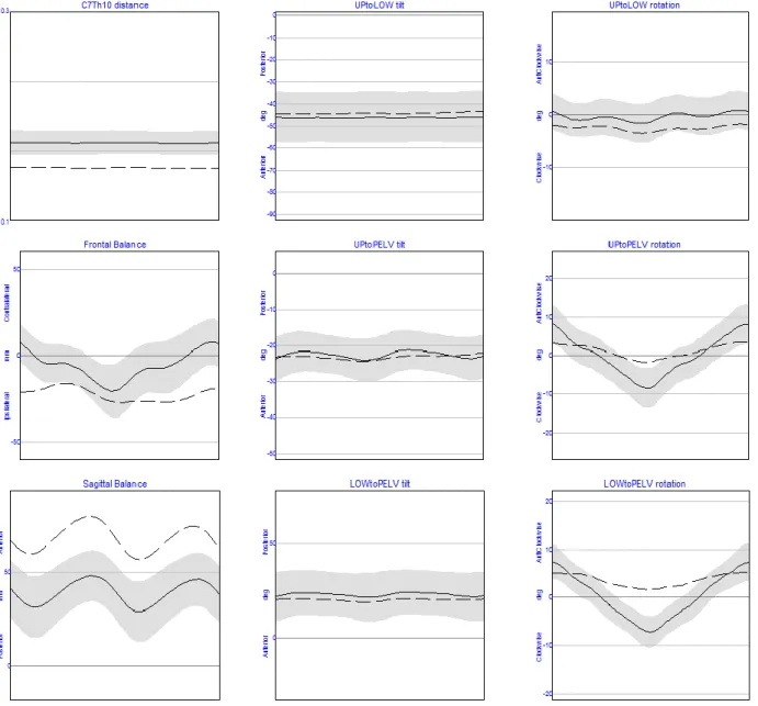
Figure 6. Trunk model results of a scoliotic patient compared to standard
As an example a 16 year old scoliotic patient (48 Cobb°, right convex dorsal – left convex lumbar) (Figure 6.) and a 15 year old patient with Scheuermann’s disease (Figure 7.) was measured and processed with the Trunk Model. During the clinical measurement a 1 cm decompensation was observed. The difference in the frontal balance shows the change of this value during the gait cycle. On the sagittal balance graph a 25 mm anterior imbalance can be observed compared to the normal curve. All the 3 tilt graphs are within the standard range. The rotation graphs follow the normal curve with reduced amplitude in the segments compared to the pelvis and with the static offset caused by the rotation of the thoracic spine.
Figure 7. Trunk model results of a patient with Scheuermann’s disease compared to standard. In case of the patient with Scheuermann’s disease the most prominent difference can be observed in the sagittal balance graph. Only a minimal gap can be seen in the frontal balance graph, while the rotation graphs overlap the normal curve. The anterior tilt which characterises the disease can be detected on the tilt graphs. The most prominent tilt can be observed in the UPtoPELV tilt graph.
In our trunk model we use the original marker set of Vicon PlugInGait model, however extra markers may allow more accurate measurements. Additional marker may be positioned over the apical vertebra of a scoliotic curve showing the rotation of the thorax exactly at the point of the maximal vertebral rotation. Another possibility for further development of our model is to mark the Th12 vertebra which would show the complete thoracic kyphosis on the UPtoLOW tilt graph.
5. Conclusion
Authors present a possible motion capture model for segmental modelling of the trunk. In the model tilting and rotational position, as well as movements of the upper- and lower part of the thorax and the pelvis are observed together with the frontal- and sagittal balance of the spine during gait. The possibility of applying the model is a subject for further investigations.
Deformities under consideration are scoliosis, Scheuermann’s disease, osteoporotic spine deformities and any other spinal or trunk disorders.
REFERENCES
1. Bunnell WP, et al. Outcome of spinal screening. Spine (Phila Pa 1976) 1993 Sep 15;18(12):1572-80.
2. Scoles PV, Latimer BM, DigIovanni BF, Vargo E, Bauza S, Jellema LM, et al. Vertebral alterations in Scheuermann's kyphosis. Spine, 1991;16(5):509-15.
3. Frank Damborg, Vilhelm Engell, Mikkel Andersen, Kirsten Ohm Kyvik, Karsten Thomsen, et al.
Prevalence, concordance, and heritability of Scheuermann kyphosis based on a study of twins. J Bone Joint Surg Am. 2006 Oct;88(10):2133-6 17015588.
4. Luk KD, Cheung KM, Lu DS, Leong JC., et al. Assessment of scoliosis correction in relation to flexibility using the fulcrum bending correction index. Spine (Phila Pa 1976) 1998 Nov 1;23(21):2303-7.
5. Vicon Oxford Metrics. Plug-In Gait Manual. Available from: URL: http://www.irc- web.co.jp/vicon_web/news_bn/PIGManualver1.pdf
6. Kadaba MP, Ramakrishnan HK, Wootten ME, Gainey J, Gorton G, Cochran GV, et al. Repeatability of kinematic, kinetic, and electromyographic data in normal adult gait. J Orthop Res. 1989;7(6):849-60.
7. Kadaba MP, Ramakrishnan HK, Wootten ME, et al. Measurement of lower extremity kinematics during level walking. J Orthop Res. 1990 May;8(3):383-92.
8. Ounpuu S, Gage JR, Davis RB, et al. Three-dimensional lower extremity joint kinetics in normal pediatric gait. J Pediatr Orthop. 1991 May-Jun;11(3):341-9.
9. Negrini S, Negrini A, et al. Postural effects of symmetrical and asymmetrical loads on the spines of schoolchildren. Scoliosis. 2007 Jul 9;2:8.
10. Lazennec JY, Brusson A, Rousseau MA, et al. Hip-spine relations and sagittal balance clinical consequences. Eur Spine J. 2011 Sep;20 Suppl 5:686-98. doi: 10.1007/s00586-011-1937-9. Epub 2011 Jul 28.
We acknowledge the generous support of NKTH – “Gerinőr2” project in funding this project. Also skilful assistance of the staff of the Paediatric Ward of Department of Orthopaedics at Semmelweis University is very well acknowledged.