The operation of the quadrupole mass filter under the severe entrance conditions imposed by satellite environment is investigated theoretically and experimentally. This use imposes several limitations not ordinarily experienced in the laboratory. First, the charged particles must enter the filter directly without having contacted any surface. Second, the ions may have a large component of radial velocity. Third, to achieve maximum sensitivity, the entrance aperture must be as large as possible.
Paul and Raether [3] first showed that the quadrupole electric field can be used as a mass filter with variable band-pass characteristics. Under Professor Paul's leadership the group at Bonn [4] has shown that the filter can be used to achieve high resolution.
The formal solutions of the equations of motion of the ions as they pass through the mass filter are given by the Mathieu equation [2]. These solu
tions are expressed as infinite series; the coefficients are given as continued fractions. In order to learn much about the trajectories by this means, the use of a large computer is required.
Simple, approximate solutions for the motions of the ions in one of the planes of symmetry have been obtained through the use of Newton's second law of motion. By the adjustment of a single constant the approxi
mate solutions are brought into agreement with the formal solution at a boundary. When this is done, the predictions of the approximate solutions are excellent over the region of the stability diagram used in mass spectro
scopy. Further, they give a physical insight to the operation of the mass filter.
A n experimental mass filter has been probed with a small ion beam, and the transmission efficiencies observed under conditions similar to those expected in a satellite. The entrance geometry is found to have a great influence on the transmission efficiency.
1 This research was supported in whole or in part by the United States Air Force under Contract N o . A F 19(604)-5911, monitored by the Geophysics Research Directo
rate, Air Force Cambridge Research Center, Air Research and Development Command, United States Air Force, Bedford, Massachusetts.
20-60143045 I & Μ
T H E O R Y
In Fig. 1 is shown schematically the geometry of the mass filter and the manner of excitation. The filter consists simply of four round rods arranged so that the electric field in the space between them is essentially hyperbolic.
They are electrically connected in pairs and excited with both A . C . and D.C. voltages. For use as a mass spectrometer, the magnitude of the D.C.
voltage is about one-sixth that of the peak A . C . voltage. Note that the x- and ^-components of the gradient are proportional to χ and y respectively.
For positive ions, the D.C. component of the gradient in the x-direction is focusing, in the .y-direction it is defocusing. Thus, it is expected that the trajectories in the two planes are quite dissimilar. The force in the x-direction is independent of y and vice versa. In the x-direction the positive ion is stable in the D.C. field. In the absence of A . C . fields, the ion experiences simple harmonic motion. When A . C voltage is added to the D . C , it is not sur
prising that the amplitude resembles that of a resonant system excited slightly off resonance. This is shown in the trajectory in Fig. 2, which was derived with the help of a digital computer, a is proportional to the D.C. field and q is proportional to the A . C . field.
In Fig. 3 is shown the calculated trajectory in the ^-direction. The initial conditions are the same for Figs. 2 and 3. In the ^-direction the ion moves in response to the applied fields and essentially in synchronism with it. In the x-direction the frequency of the oscillation is nearly half that of the applied voltage.
The stability of the ions in the y-z plane results from their motion in the non-uniform electric field. Starting first with the motion of an ion in a uni
form field which varies sinusoidally with time, it is readily shown that the displacement from the mean position is 180° out of phase with the applied force. If the non-uniformities of the field are small relative to the average value over the excursion, we may assume that the motion is nearly sinusoidal.
Note that the inwardly-directed force is greatest at the maximum excursion of the ion from the axis, and that it exceeds the outwardly-directed force
Fig. 1—Quadrapole mass filter. V=(Vac+ Vac cos <ot) I ^ I .
t Μ 52 40 48 56 72 80 Μ 96\ 104
Fig. 2.
Fig. 2.—Ion trajectory in the x-z plane.
Fig. 3.—Ion trajectory in the y-z plane.
Fig. 3.
which occurs at the minimum excursion. Thus, the momentum impulse given to the ion during a cycle is not zero. Further, it is directed toward the axis. This is the means by which the defocusing action of the D.C.
field is overcome by the motion of the ions in the non-uniform field.
The average position of the ion is influenced by the difference between the inwardly-directed acceleration (from the A . C . field) and the outwardly- directed acceleration (from the D.C. field). The net acceleration is pro
portional to the displacement, and so the motion of the time-average posi
tion is sinusoidal. In Fig. 3 is shown a half-period of this motion. The approximate solution predicts within a few per cent the number of cycles of the applied r.f. voltage during the half-period of oscillation exhibited in Fig. 3.
It may be assumed that the ion exhibits its stability and proceeds to the collector, no matter how far down the filter it is, when it has passed the quarter-period position. This occurs at ω ί ^ 4 8 in Fig. 3. If such an ion also just misses the rods at this mid-position, then an ion on a less stable orbit strikes the rods before this position is reached and is removed. For ions which enter the filter on the axis, with an arbitrary component of radial velocity, the approximate solution predicts that the number of oscilla
tions required for the ion to reach maximum amplitude is
« = 1.36(m/Am)(^. (1)
Empirically, Paul has found that the number of oscillations required is
np = 5(m/Am)(t\ (2)
In these expressions A m is the peak width at the base. The inequality of equations (1) and (2) may be due to either of two possibilities. It may re-
Fig. 4. Fig. 5.
Fig. 4.—Mass filter.
Fig. 5.—Ion source end of mass filter.
present the difference between the theoretical limit and what has been observed experimentally. Perhaps Paul's empirical relation expresses the number of cycles required for ions which enter with small values of radial position and velocity to demonstrate their instability.
A P P A R A T U S
The experimental mass filter is shown in Fig. 4. The rods are 3.14 cm in diameter, 1 m long. The large diameter was chosen to facilitate the use of a small ion beam as a probe to investigate the transmission efficiency as a function of the entrance position and angle. The length was chosen to assure that the ions experience a sufficient number of cycles in the filter to demon- strate their stability.
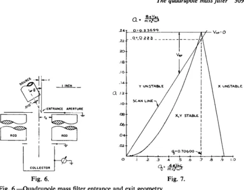
Fig. 5 pictures the source end of the filter. It illustrates the manner in which the 0.25 mm beam of well-collimated potassium ions may be directed at an angle of 30° relative to the axis of the filter. The source can also be moved along a diameter of the entrance aperture. Thus, the transmission efficiency can be observed as functions of both entrance position and angle.
The entrance and exit geometries are shown in Fig. 6. The grounded aperture is placed as close to the rods as feasible.
The ion source follows a suggestion made by Professor Paul. It is simply
Fig. 6. Fig. 7.
Fig. 6.—Quadrupole mass filter entrance and exit geometry.
Fig. 7.—Stability diagram.
the ion optics of a cathode ray tube with the electron emitter replaced by a thermal ion emitter. The energy of the incident ions is varied between 15 and 150 eV. A t the lower value the velocity of potassium ions approximates satellite velocity 8000 m/sec.
A push-pull, self-excited oscillator is used. The D.C. potentials are ob
tained from the A . C . by rectification and filtering. The mass scan is ac
complished by varying the applied potentials with a motor-driven variable transformer.
E X P E R I M E N T A L D A T A
The manner in which the filter is operated is illustrated in Fig. 7. The Mathieu equation solutions are characterized as being stable or unstable. The con
ditions of stability are determined solely by the locus of the operating point in the a, q diagram. The dependence of a and q upon the operating para
meters is illustrated. The region below a = 0.237 is divided into three regions:
χ stable, y unstable; χ and y stable; and χ unstable, y stable. A t a given level of excitation the ions of all masses lie along the scan line. Only those masses which lie on that portion of the scan line which passes through the triangle are stable. Those to the left are lost to the negatively-charged
>>-rods; those to the right are lost to the positively-charged x-rods. By ad- j usting the slope of the scan line the width of the stable region is controlled;
P O T A S S I U M 41
0.231 781 KC
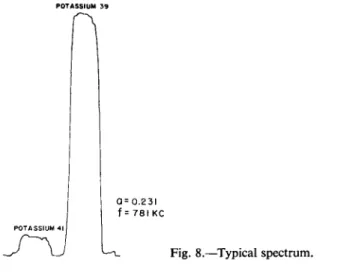
Fig. 8.—Typical spectrum.
this alters the resolving power. Changing the A . C . and D.C. voltages pro
portionally causes the masses to move along the scan line so that they pass through the stable region successively. The heavy ions lie nearer the origin, the lighter farther away. A typical spectrum, which displays the main iso
topes of potassium, appears in Fig. 8.
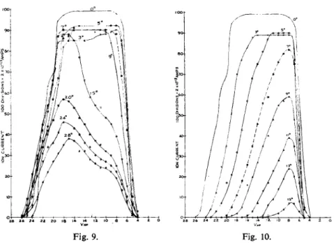
The data of Figs. 9 and 10 indicate the shape of a single peak as the vol
tages are scanned to cause the corresponding mass to move through the stability region. Since the corner of the stability region can be located with great accuracy, the D.C. voltage was referenced from its value at the apex.
The injection energy of the ions was 140 V. The frequency of the A . C . voltage was 1.7 Mc. Fig. 9 indicates the transmission as a function of the angle of entry for ions entering on the axis, directed toward the x-rod. Fig.
10 is similar for the ions directed toward the j>-rod.
The data of Figs. 9 and 10 illustrate several important features of the operation of the quadrupole mass filter. First, the transmission efficiency in the ^-direction is less vulnerable to injection off normal than the >>- direction. This appears to be due to the influence of the region where the fields are of less than full intensity. This represents operation in the left portion of the stability diagram. Here the weaker fields are seen to be χ stable, y unstable. Note also in Fig. 10 that the maximum transmission efficiency occurs near the ^-stability limit, where the .y-stability is greatest.
The same effect is present in Fig. 9, but is less apparent.
The data of Figs. 11 through 14 were taken somewhat differently. First,
the 3 9K peak was scanned and the spectrum observed on a strip chart
recorder. Then the maximum value of the current was recorded. In these figures the data which are plotted represent the maximum peak height, and no attention was given to the locus on the scan line at which it occurs. The
Fig. 9. Fig. 10.
Fig. 9.—Angular dependence on axis, x.
Fig. 10.—Angular dependence on axis, y.
conditions under which these data were taken resemble satellite environ
ment in that the ion injection energy is 15 eV.
These data indicate the transmission efficiency as functions of the entrance position, the entrance angle, and the power (frequency) level of excitation of the filter. The data are presented for only two azimuthal positions, χ and y. In the evaluation of the results to be expected at other azimuthal
-0.4 -0.3 -0.2 -0.1 0 0.1 0.2 0.3 0.4 _r_
«0
Fig. 11.—Peak ion current as a function of the entrance position at different power levels for injection at 10° in the x-z plane.
positions it should be noted that the ion must be stable in both x- and y- directions if it is to reach the collector. The .y-component of motion be
comes appreciable for even moderate departures from the x-direction.
The first glimpse at these data impresses one with the great difference between the response in the χ and j-directions. The experiment does not tell how much of this difference is due to the forces to which the ions are subjected as they pass through the fringing fields, but reference to Fig. 2 and 3 suggest that the most of the difference observed may be due to this effect.
Fischer [1] has used the Mathieu equations to calculate the entrance conditions which will permit transmission of the ions to the collector.
Particularly for entrance off-axis, the transmission is quite dependent on the
Fig. 13.—Peak ion current as a function of the entrance position at different power levels for injection at 30° in the x-z plane.
Fig. 12.—Peak ion current as a function of the entrance position at different power levels for injection at 10° in the y-z plane.
phase of the r.f. fields at the time the ion enters the filter. Fischer has shown that the transmission efficiency is lowered for entrance on-axis at increasing angles, and also for entrance parallel to the axis, but at increasing distances from the axis. Although he did not include in his publications the calculated efficiency for entrance off-axis, at a non-normal angle, it seems probable that the combination would result in lower efficiency than either alone. The data of Fig. 14 do not substantiate this assumption. They indicate clearly that the transmission efficiency is greater near the edge of the aperture than it is in the center. It is not suggested that the anticipated Mathieu equation results are wrong; rather, the forces to which the ions are subjected as they pass through the fringing fields are responsible for these results.
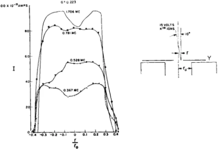
Another apparent anomaly is evident in Fig. 13. The transmission effi- ciency is lower for the highest level of excitation. These data have been double-checked and are real. This may be likened to a resonant condition.
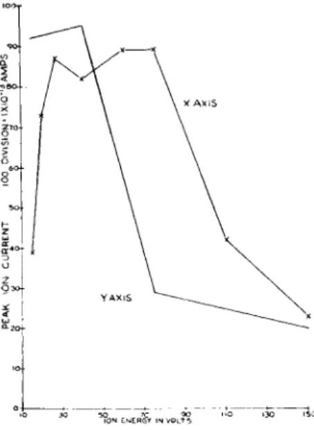
Actually, it is thought to be an indication of the importance of the number of cycles the ion spends in the fringing field. Fig. 15 presents more data on this anomaly. Here we have the transmission efficiency as a function of the incident ion energy. The region above about 60 eV is as anticipated: the collector currents decrease as the incident energy is increased. The decrease in collector current as the ion energy is lowered below 30 V in the x-direction is explainable only in terms of the entrance conditions. While the orbit or trajectory is stable in the x-direction for weak fields, the motion is also resonant. Hence, it is possible that the radial motion of the ions is large at the time they enter the uniform field region. Further, the transient mo- mentum impulse which the ions receive as they enter the filter is a function of the number of cycles spent in the fringing field.
Fig. 14.—Peak ion current as a function of the entrance position at different power levels for injection at 30° in the y-z plane.
Fig. 15.—Ion current as a function of injec- tion energy for injection on the axis at an angle of 30°. The entrance aperture is 0.065 inches, the frequency of excitation 1.706 M, and the value of a at the intersection of the scan line and the line # = 0.706 is 0.223.
S U M M A R Y
The experimental data indicate the transmission efficiency for ions incident upon the mass filter with satellite velocity at angles from 0° to 30° with the axis of the instrument. The power level of the excitation of the filter varied between 0.35 and 64 W , while the frequency of excitation varied from 0.367 M c to 1.706 Mc. A n unexpectedly large dependence of the trans- mission efficiency upon the entrance conditions was found. The efficiency is higher than expected for off-axis entry at low power levels. The transient momentum impulse received by the ions as they traverse the fringing fields is considered to be the cause of this effect. There is strong indication that the number of cycles the ion spends in the fringing field is of major importance.
The stability in the x-z plane is found to be quite different than that in the y-z plane. In part, this is due to the fact that the ions are stable in the fringing fields in the x-z plane and unstable in the y-z plane. In other instan- ces the resonant condition of ions in the x-z plane appears to lower their transmission efficiency.
The spatial distribution of the fields at the entrance to the filter is of major importance. This is particularly true when it is desired to obtain maximum sensitivity at minimum power levels for off-axis entry, as is en- countered in satellite applications.
The quadrupole mass filter appears to be very well suited for use as the analyzer portion of a mass spectrometer for satellite applications.
R E F E R E N C E S
1. FISCHER, E., OSBERGHAUS, O. and PAUL, W., Forschr-Ber. d. Wirtsch. Ministeriums Nordrhein-Westfalen Nr. 415.
2. MCLACHLAN, N . W., Theory and Applications of Mathieu Functions. Oxford, 1947.
3. PAUL, W . and RAETHER, Μ., Z. Phys. 140, 262 (1955).
4. PAUL, W., REINHARD, H . P. and VON ZAHN, U . , ibid. 152, 143 (1958).