Highly Automated Vehicle Systems
Péter Dr. Gáspár Petra Dr. Aradi Annamária Décsei-Paróczi
Szilárd Aradi
Zsolt Dr. Szalay
Highly Automated Vehicle Systems
by Péter Dr. Gáspár, Petra Dr. Aradi, Annamária Décsei-Paróczi, Szilárd Aradi, and Zsolt Dr. Szalay Publication date 2014
Copyright © 2014 Dr. Gáspár Péter, Dr. Aradi Petra, Décsei-Paróczi Annamária, Aradi Szilárd, Dr. Szalay Zsolt
A tananyag a TÁMOP-4.1.2.A/1-11/1-2011-0042 azonosító számú „Mechatronikai mérnök MSc tananyagfejlesztés‖ projekt keretében készült. A tananyagfejlesztés az Európai Unió támogatásával és az Európai Szociális Alap társfinanszírozásával valósult meg.
A kiadásért felel a(z): BME MOGI Felelős szerkesztő: BME MOGI
Table of Contents
1. Control design aspects of highly automated vehicles ... 1
1. Motivation ... 1
1.1. Reducing accident number and accident severity ... 1
1.2. Saving energy and reducing harmful exhaust emission ... 2
1.3. The role of mechatronics ... 3
2. Design aspects ... 4
3. Automation levels ... 5
3.1. Warning ... 5
3.2. Support ... 6
3.3. Intervention ... 8
3.3.1. Semi-automated intervention ... 8
3.3.2. Highly automated intervention ... 9
3.4. Full Automation ... 14
2. Layers of integrated vehicle control ... 16
1. Levels of intelligent vehicle control ... 16
1.1. Electronic System Platform ... 16
1.2. Intelligent Actuators ... 17
1.3. Integrated Vehicle Control ... 17
1.4. Direct V2V, V2I Interactions ... 17
1.5. Control of Vehicle Groups and Fleets ... 17
2. Layers of vehicle control ... 17
2.1. Command layer ... 20
2.2. Motion Vector ... 20
2.3. Execution Layer ... 20
3. Integrated control ... 21
4. Distributed control structure ... 23
3. Environment Sensing (Perception) Layer ... 25
1. Radar ... 25
2. Ultrasonic ... 30
3. Video camera ... 32
3.1. Image sensor attributes ... 33
4. Image processing ... 35
5. Applications ... 36
6. Night Vision ... 38
7. Laser Scanner (LIDAR) ... 39
8. eHorizon ... 44
8.1. NAVSTAR GPS ... 44
8.2. GLONASS ... 46
8.3. Galileo ... 46
8.4. BeoiDou (COMPASS) ... 47
8.5. Differential GPS ... 49
8.6. Assisted GPS ... 50
9. Data Fusion ... 50
4. Human-Machine Interface ... 53
1. Requirements ... 53
2. HMI classifications ... 55
2.1. Primary HMI components ... 55
2.1.1. Input channels ... 56
2.1.2. Output channels ... 56
2.2. Secondary HMI components ... 57
2.2.1. Input channels ... 57
2.2.2. Output channels ... 57
3. HMI technologies ... 58
3.1. Mechanical interfaces ... 58
3.1.1. Pedal, lever ... 58
3.1.2. Steering wheel ... 59
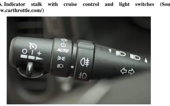
3.1.3. Button, switch, stalk, slider ... 59
3.1.4. Integrated controller knob ... 59
3.1.5. Touchscreen ... 60
3.2. Acoustic interfaces ... 62
3.2.1. Beepers ... 62
3.2.2. Voice feedback ... 62
3.2.3. Voice control ... 63
3.3. Visual interfaces ... 63
3.3.1. Analogue gauge ... 63
3.3.2. LCD display ... 64
3.3.3. OLED display ... 65
3.3.4. Head-Up Display (HUD) ... 67
3.3.5. Indicator lights (Tell-tales) ... 68
3.4. Haptic interfaces ... 69
4. Driver State Assessment ... 69
5. Trajectory planning layer ... 72
1. Longitudinal motion ... 72
2. Lateral motion ... 73
3. Automation level ... 76
4. Auto-pilot ... 77
5. Motion vector generation ... 79
6. Trajectory execution layer ... 80
1. Longitudinal control ... 80
1.1. Design of speed profile ... 80
1.2. Optimization of the vehicle cruise control ... 83
1.3. Implementation of the velocity design ... 84
1.4. Extension of the method to a platoon ... 87
2. Lateral control ... 89
2.1. Design of trajectory ... 89
2.2. Road curve radius calculation ... 91
7. Intelligent actuators ... 94
1. Vehicular networks ... 95
2. Safety critical systems ... 96
3. Steering ... 99
4. Engine ... 103
5. Brakes ... 103
5.1. Electro-pneumatic Brake (EPB) ... 104
5.2. Elector-hydraulic Brake (EHB) ... 105
5.3. Electro-mechanic brake (EMB) ... 106
6. Transmission ... 107
6.1. Clutch ... 107
6.2. Automated Manual Transmission (AMT) ... 108
6.3. Dual Clutch Transmission (DTC/DSG) ... 109
6.4. Hydrodynamic Transmission (HT) ... 109
6.5. Continuously Variable Transmission (CVT) ... 110
8. Vehicle to Vehicle interactions (V2V) ... 111
1. Mobile Ad Hoc Network Theory ... 111
1.1. Routing ... 114
1.2. Security ... 115
1.3. Quality of Service (QoS) ... 117
1.4. Internetworking ... 117
1.5. Power Consumption ... 117
2. V2V standards ... 117
2.1. IEEE 802.11p (WAVE) ... 118
2.2. IEEE 1609 ... 119
2.3. SAE J2735 ... 120
3. V2V applications ... 121
3.1. Traffic Safety ... 121
3.2. Traffic Efficiency ... 123
3.3. Infotainment and payments ... 124
3.4. Other applications ... 124
9. Vehicle to Infrastructure interaction (V2I) ... 126
1. Architecture ... 126
2. Wireless Technologies ... 127
2.1. DSRC ... 127
2.2. Bluetooth ... 127
2.3. WiFi ... 129
2.4. Mobile networks ... 129
2.5. Short range radio ... 130
3. Applications ... 130
3.1. Safety ... 130
3.2. Efficiency ... 131
3.3. Payment and information ... 132
10. Vehicle to Environment interactions (V2E) ... 133
1. Conventional technologies ... 133
2. Camera-based systems ... 134
3. Radar, ultrasonic and laser detectors ... 135
4. Floating Car Data (FCD) ... 136
11. Different methods for platooning control ... 137
1. Control tasks ... 138
2. Platooning strategies ... 140
12. Vehicle control considering road conditions ... 145
13. Design of decentralized supervisory control ... 148
14. Fleet Management Systems ... 151
1. Motivation ... 151
2. General requirements in transportation ... 152
2.1. Cost reduction ... 152
2.2. Logistics management ... 152
2.3. Vehicle categories ... 152
3. System Functions ... 152
3.1. Data acquisition ... 153
3.2. Data processing ... 153
3.3. Data transmission ... 153
3.4. Identification tasks ... 153
3.5. Alerts ... 153
3.6. Positioning ... 153
3.7. Central system (Back office) ... 154
3.8. User system (Front office) ... 154
4. Architecture of Fleet Management Systems ... 154
4.1. On-board units (OBU) ... 155
4.1.1. In-Vehicle Data Acquisition ... 155
4.2. Communication ... 157
4.3. Central system ... 158
4.4. User System ... 159
4.4.1. Data displaying, querying, reporting ... 159
4.4.2. Map display ... 161
15. References ... 163
References ... 164
List of Figures
1.1. Road fatalities in the EU since 2001 (Source: CARE) ... 1
1.2. Road fatalities by population since 2001 (Source: CARE) ... 1
1.3. European roadmap for moving to a low-carbon economy (Source: EU) ... 2
1.4. European Euro 6 emissions legislation (Source: DAF) ... 2
1.5. The effect of collision speed on fatality risk (Source: UNECE) ... 3
1.6. Situations when driver assistance is required. (Source: HAVEit) ... 4
1.7. Automation level approach by the HAVEit system. (Source: HAVEit) ... 5
1.8. Driver drowsiness warning: Time to take a coffee break! (Source: HAVEit) ... 6
1.9. LDW support guiding the driver back into the centre of the lane. (Source: Mercedes-Benz) ... 6
1.10. Counter-steering torque provided to support keeping the lane. (Source: TRW) ... 7
1.11. Warning for misuse of lane assist for autonomous driving. (Source: Audi) ... 7
1.12. Parking space measurement (Source: Bosch) ... 7
1.13. Principle of the operation of the parking aid systems (Source: Bosch) ... 8
1.14. ACC distance control function for commercial vehicles (Source: Knorr-Bremse) ... 9
1.15. Steps of collision mitigation with an ACC System (Source: Toyota) ... 9
1.16. Temporary Auto Pilot in action at 130 km/h speed (Source: Volkswagen) ... 10
1.17. Highly automated driving on motorways (Source: BMW) ... 10
1.18. Test vehicle with automated highway driving assist function (Source: Toyota) ... 11
1.19. Demonstrating automated roadwork assistance functionality. (Source: HAVEit) ... 12
1.20. Demonstration of a platoon control ... 12
1.21. Hierarchical structure applied in the PATH project ... 13
1.22. Google‘s self-driving test car, a modified hybrid Toyota Prius (Source: http://www.motortrend.com) ... 14
2.1. Levels of intelligent vehicle control (Source: Prof. Palkovics) ... 16
2.2. Initial model of the HAVEit architecture simulation ... 18
2.3. Levels of intelligent vehicle control (Source: PEIT) ... 19
2.4. HAVEit System Architecture and Layer structure (Source: HAVEit) ... 19
2.5. Powertrain Control Structure of the execution layer (Source: PEIT) ... 21
2.6. Scheme of the integrated control ... 21
2.7. Reference control architecture for autonomous vehicles (NIST) ... 23
3.1. Sensor devices around the vehicle (Source: Prof. Dr. G. Spiegelberg) ... 25
3.2. Radar-based vehicle functions (Source SaberTek) ... 26
3.3. Principle of FM-CW radars (Source: Fujitsu-Ten) ... 27
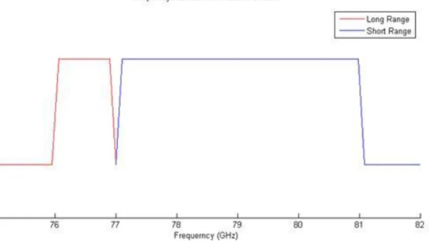
3.4. Frequency allocation of 77 GHz band automotive radar ... 27
3.5. Bosch radar generations (Source: Bosch) ... 28
3.6. Measurement principle of ultrasonic sensor ... 30
3.7. The emitted and echo pulses (Source: Banner Engineering) ... 30
3.8. Bosch ultrasonic sensor (Source: Bosch) ... 31
3.9. Ultrasonic sensor system (Source: Cypress) ... 31
3.10. Structure of CCD (Source: Photonics Spectra) ... 32
3.11. Structure of CMOS sensor (Source: Photonics Spectra) ... 32
3.12. Principle of colour imaging with Bayer filter mosaic (Source: http://en.wikipedia.org/wiki/File:Bayer_pattern_on_sensor_profile.svg) ... 34
3.13. Bosch Multi Purpose Camera (Source: http://www.bosch-automotivetechnology.com/) ... 36
3.14. Bosch Stereo Video Camera (Source: http://www.bosch-automotivetechnology.com/) ... 37
3.15. Passive thermal image sensor (source: http://www.nature.com, BMW)) ... 39
3.16. Night vision system display (source: BMW) ... 39
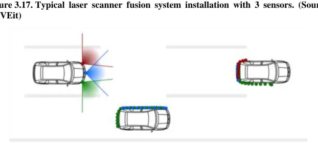
3.17. Typical laser scanner fusion system installation with 3 sensors. (Source: HAVEit) ... 40
3.18. :The laser scanner sensor itself and its installation point front left below the beams. (Source: HAVEit) ... 40
3.19. Multi-layer technology enables pitch compensation and lane detection. (Source: HAVEit) ... 41
3.20. Velodyne HDL-64E laser scanner (Source: Velodyne) ... 41
3.21. General architecture of laser scanners (Source: Velodyne) ... 42
3.22. Laser scanner fusion with 360 degrees scanning. (Source: IBEO) ... 43
3.23. Image of a point cloud from a laser scanner (Source: Autonomous Car Technology) ... 43
3.24. Position calculation method based on 3 satellite data. (Source: http://www.e-education.psu.edu) 45
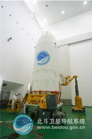
3.25. Long March rocket head for launching Compass G4 satellite (Source: http://www.beidou.gov.cn) 47
3.26. BeiDou 2nd Deployment Step(Source: http://gpsworld.com/the-system-vistas-from-the-summit/) 48
3.27. Comparison of BeiDou with GPS(Source: http://gpsworld.com/china-releases-public-service-
performance-standard-for-beidou/) ... 49
3.28. Differential GPS operation (source: http://www.nuvation.com) ... 50
3.29. Environment sensor positions on the HAVEit demonstrator vehicle. (Source HAVEit) ... 51
3.30. Block diagram of a sensor data fusion system: inputs and outputs. (Source HAVEit) ... 51
4.1. Example for the congested and confusing HMI (Source: Knight Rider series) ... 53
4.2. The vision of project AIDE (Source: AIDE) ... 54
4.3. HMI design: AQuA, take over request. (Source: HAVEit) ... 54
4.4. BMW iDrive controller knob (Source: BMW) ... 57
4.5. Splitview technology of an S-Class vehicle (Source: Mercedez-Benz) ... 57
4.6. Indicator stalk with cruise control and light switches (Source: http://www.carthrottle.com/) ... 59
4.7. Integrated radio and HVAC control panel with integrated knobs (Source: TRW) ... 59
4.8. Resistive touchscreen (Source: http://www.tci.de) ... 60
4.9. Projected capacitive touchscreen (Source: http://www.embedded.de) ... 61
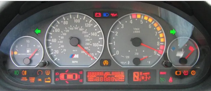
4.10. Old instrument cluster: electronic gauges, LCD, control lamps (Source: BMW) ... 63
4.11. Liquid crystal display operating principles (Source: http://www.pctechguide.com) ... 64
4.12. A flexible OLED display prototype (Source: http://www.oled-info.com) ... 66
4.13. The SPORT+ and COMFORT modes of the BMW 5 Series‘ instrument cluster (Source: http://www.bmwblog.com) ... 67
4.14. The SPORT+ and COMFORT modes of the BMW 5 Series‘ instrument cluster (Source: http://www.bmwblog.com) ... 67
4.15. Head-Up Display on the M-Technik BMW M6 sports car. (Source. BMW) ... 67
4.16. Next generation HUD demonstration (Source: GM) ... 68
4.17. Excerpt from the ECE Regulations (Source: UNECE) ... 69
4.18. Combination of driver state assessment (Source: HAVEit) ... 70
5.1. Speed and distance profile comparison of standard ACC versus Cooperative ACC systems (Source: Toyota) ... 72
5.2. Illustration of the parallel parking trajectory segmentation (Source: Ford) ... 74
5.3. Layout of common parking scenarios for automated parking systems (Source: TU Wien) ... 74
5.4. Traffic jam assistant system in action (Source: Audi) ... 74
5.5. The operation of today‘s Lane Keeping Assist (LKA) system (Source: Volkswagen) ... 75
5.6. Automated Highway Driving Assist system operation (Source: Toyota) ... 76
5.7. Scenarios of single or combined longitudinal and lateral control (Source: Nissan) ... 76
5.8. The manoeuvre grid with priority rankings (Source: HAVEit) ... 77
5.9. The decision of the optimum trajectory (Source: HAVEit) ... 78
6.1. Division of road ... 80
6.2. Simplified vehicle model ... 81
6.3. Implementation of the controlled system ... 84
6.4. Architecture of the low-level controller ... 85
6.5. Architecture of the control system ... 88
6.6. Counterbalancing side forces in cornering maneuver ... 89
6.7. Relationship between supply and demand of side friction in a curve ... 90
6.8. Relationship between curve radius and safe cornering velocity ... 91
6.9. The arc of the vehicle path ... 92
6.10. Validation of the calculation method ... 93
7.1. Intelligent actuators influencing vehicle dynamics (Source: Prof. Palkovics) ... 94
7.2. The role of communication networks in motion control (Source: Prof. Spiegelberg) ... 95
7.3. CAN bus structure (Source: ISO 11898-2) ... 95
7.4. Categorization of failure during risk analysis (Source: EJJT5.1Tóth) ... 97
7.5. Characterization of functional dependability (Source: EJJT5.1 Tóth) ... 97
7.6. Redundant energy management architecture (Source: PEIT) ... 99
7.7. Electronic power assisted steering system (TRW) ... 100
7.8. Superimposed steering actuator with planetary gear and electro motor (ZF) ... 100
7.9. Steer-by-wire actuator installed in the PEIT demonstrator (Source: PEIT) ... 101
7.10. Safety architecture of a steer-by-wire system (Source: HAVEit) ... 102
7.11. Direct Adaptive Steering (SbW) technology of Infiniti (Source: Nissan) ... 103
7.12. Retrofit throttle-by-wire (E-Gas) system for heavy duty commercial vehicles (Source: VDO) 103 7.13. Layout of an electronically controlled braking system (Source: Prof. von Glasner) ... 104
7.14. Layout of an Electro Pneumatic Braking System (Source: Prof. Palkovics) ... 104
7.15. Layout of an Electro Hydraulic Braking System (Source: Prof. von Glasner) ... 106
7.16. Layout of an Electro Mechanic Brake System (Source: Prof. von Glasner) ... 106
7.17. Clutch-by-wire system integrated into an AMT system (Source: Citroen) ... 108
7.18. Schematic diagram of an Automated Manual Transmission (Source: ZF) ... 108
7.19. Layout of a dual clutch transmission system (Source: howstuffworks.com) ... 109
7.20. Cross sectional diagram of a hydrodynamic torque converter with planetary gear (Source: Voith) 109 7.21. CVT operation at high-speed and low-speed (Source: Nissan) ... 110
8.1. V2V interactions (Source: http://www.kapsch.net) ... 111
8.2. Infrastructure-based and Ad hoc networks example (Source: http://www.tldp.org) ... 111
8.3. Vehicular Ad Hoc Network, VANET (source: http://car-to-car.org) ... 112
8.4. Multi-hop routing (Source: http://sar.informatik.hu-berlin.de) ... 114
8.5. Multicast communication (Source: http://en.wikipedia.org/wiki/File:Multicast.svg) ... 114
8.6. Bogus information attack ... 116
8.7. V2V standards and communication stacks (Source: Jiang, D. and Delgrossi, L.) ... 117
8.8. DSRC spectrum band and channels in the U.S. ... 118
8.9. DSRC spectrum allocation worldwide ... 119
8.10. V2V application examples (forrás:http://gsi.nist.gov/global/docs/sit/2010/its/GConoverFriday.pdf) 121 8.11. Hazardous location warning (source: http://car-to-car.org) ... 122
8.12. Privileging fire truck (source: http://car-to-car.org) ... 122
8.13. Reporting accidents (source: http://car-to-car.org) ... 123
8.14. Intelligent intersection (source: http://car-to-car.org) ... 124
8.15. V2V based Cooperative-adaptive Cruise Control test vehicle. (Source: Toyota) ... 124
9.1. Architecture example of V2I systems. (Source: ITS Joint Program Office, USDOT) ... 126
9.2. Collisions avoided using Adaptive Frequency Hopping ... 128
9.3. Example safety applications with the integration of DSRC and roadside sensors (Source: http://www.toyota-global.com) ... 130
9.4. Dynamic traffic control supported by DSRC (Source: http://www.car-to-car.org/) ... 131
10.1. Combined pedestrian detection (Source: http://www.roadtraffic-technology.com, AGD Systems) 133 10.2. Loop detector after installation (Source: http://www.fhwa.dot.gov/publications/publicroads/12janfeb/05.cfm) ... 133
10.3. Highway toll control cameras (Source: www.nol.hu) ... 134
10.4. Portable speed warning sign at city entrance. (Source: http://www.telenit.hu) ... 135
10.5. Radar-based measurement solution (Source: http://www.roadtraffic-technology.com, AGD Systems) ... 136
11.1. Illustration of a platoon in the CarSim software ... 137
11.2. Structure of a platoon system ... 137
11.3. Illustration of a platoon ... 138
11.4. Mini-platoon information structure ... 142
12.1. The effects of the forward velocity to the suspension system ... 146
12.2. The effects of the road roughness to the suspension system when the velocity is ... 146
13.1. The supervisory decentralized architecture of integrated control ... 148
14.1. System structure ... 154
14.2. General architecture of the on-board unit ... 155
14.3. Architecture of the central system ... 159
14.4. Diagram example ... 160
14.5. Example alarm log ... 160
14.6. Vehicle parameters‘ statistics example ... 161
14.7. Journey log example ... 161
14.8. Vector map example ... 162
14.9. Google Maps based FMS example ... 162
List of Tables
3.1. Continental ARS300 radar (Source HAVEit) ... 29
3.2. Comparison of FIR and NIR systems (Source: Jan-Erik Källhammer) ... 38
12.1. Values of parameters describing road spectrum ... 146
14.1. Communication system ... 157
Chapter 1. Control design aspects of highly automated vehicles
In the following pages the authors would like to provide an introduction into the design, the architecture and functionality of today‘s highly automated vehicle control systems. Thanks to the developments in electronics technology integrated into the automotive industry there has been a revolution in road vehicle technology in the past 20 years. In modern vehicles there are approximately 100 microcomputers today providing service to the driver by means of vehicle operation, comfort, assistance and safety. Electronics control almost every function inside the vehicle and there are attempts to harmonise vehicle-to-vehicle communication (V2V) and vehicle-to- infrastructure information exchange (V2I) as well. Advanced driver assistance systems (ADAS) take over more and more complex and complicated tasks from the driver like adaptive cruise control (ACC) or lane keeping assistance (LKA), to make driving even easier and safer. In the not too far future the public road vehicles will be able to drive without a driver. On one hand the technology improvements makes such functions feasible even on public roads, while on the other hand it raises new challenges to policy makers. Until that time there are a lot of tasks to be solved, several technical questions and maybe even more legal issues have to be answered.
1. Motivation
1.1. Reducing accident number and accident severity
Reducing the number of accidents and accident severity is the highest importance according to the EU objectives, but this in not only a European, but a global problem affecting the whole society. Worldwide every year almost 50 million people are injured and 1.2 million people die in road accidents; more than half of them being young adults aged 15 to 44. Forecasts indicate that, without substantial improvements in road safety, road accidents will be the second largest cause of healthy life years lost by 2030. (Source:[1])
In Europe there is no reality to further improve the currently existing road network, so the solution has to face the limited infrastructure and the even further growing demand of transport. That is why highly automated road vehicles (integrated into an intelligent environment) will have a key role in improving road safety. The EU road safety strategy defined in 2001 has achieved significant results, but there is still a lot to do. The following figures [2] below show the overall and country based progress achieved in saving lives on European roads.
Figure 1.1. Road fatalities in the EU since 2001 (Source: CARE)
Figure 1.2. Road fatalities by population since 2001 (Source: CARE)
Hungary has been recognised with the ―2012 Road Safety PIN Award‖ at the 6th ETSC Road Safety PIN Conference in 2012 for the outstanding progress made in reducing road deaths. Road deaths in Hungary have been cut by 49% since 2001, helped by a 14% decrease between 2010 and 2011. Since 2004 and its accession to the EU, Hungary quickly adapted to the rigours of membership and to the challenge of the EU 2010 target.
(Source: [3])
1.2. Saving energy and reducing harmful exhaust emission
The other global challenge is to make transportation more efficient and environment friendly. Europe accelerates its progress towards a low-carbon society in order to reach the target of an 80% reduction in emissions below the 1990 levels by 2050. To be able to achieve that, the emissions should be reduced 40% by 2030 and 60% by 2040. Each sector has to contribute to achieve this, and transportation has an essential part in that. (Source: [4])
Figure 1.3. European roadmap for moving to a low-carbon economy (Source: EU)
Although more economical engines (see also downsizing technology) also results in less emission, on the other hand there has been a great improvement recently in exhaust gas handling technology thanks to the EU regulations. Since the introduction of the Euro1 standard (1993) the harmful exhaust emission level was reduced the limit for NOX by 95% and for particulates by 97% to the Euro 6 levels. Figure 4 shows European harmful exhaust emission reduction requirements. (Source: [5])
Figure 1.4. European Euro 6 emissions legislation (Source: DAF)
Highly automated driving has also a value add to efficiency and lower harmful emissions by functions like Active Green Driving (AGD), Automated Queue Assistance (AQUA), forward thinking driving with eHorizon and velocity profile planning.
The main goal of the Active Green Driving is to reduce the fuel consumption and potentially emissions in vehicles by using e-Horizon system enhanced with environment sensors and the continuous prediction of vehicle speed profile. This includes a fuel optimal powertrain strategy and a driver support interface to give driving recommendations, in certain defined situations, using both graphical and textual information and furthermore haptic feedback in the accelerator pedal. (Source:[6])
1.3. The role of mechatronics
One should understand that there are some objective factors that electronics (mechatronics) has no alternative in the future of driving. We should not forget that most of the drivers on public road are not professional pilots, but even the most talented driver cannot compete with intelligent mechatronic systems in the following fields:
• limited information: the driver does not have access to the information that state-of-the–art sensors installed in every part of the vehicle provide. The precise and detailed information about the vehicle status and the surrounding environment is essential for decision making.(Perception layer)
• limited time: information in electronic systems propagate with the speed of light. The reaction times of mechatronic systems are significantly shorter compared to any human or mechanic systems. Information exchange between intelligent electronics inside the vehicle network is comparable to business computer networks.
• limited access: for example mechatronic systems can individually brake each and every wheel according to the circumstances that may change hundred times a second while the driver has only the possibility to press more or less the brake pedal.
The electronically networked driver assistance systems will have key factor in the increase of safety on roads.
According to statistics only 3% of traffic accidents can be traced back to technical reasons (vehicle), while 97%
of accidents are caused by human factors (driver). Beside the inadequate technical status of a certain vehicle, the major sources of vehicle accidents are wrong driver decision, inappropriate evaluation of the circumstances, or lack of consideration. The probability of wrong decisions radically increases if the driver is in bad physical or mental condition, for example tired or from some other kind of reason indisposed.
According to European accident statistics 2/3 of the accidents with serious outcome could have been avoidable by the usage of driver assistance systems. A considerable part of these accidents are pile-up accidents, from which more than half can be traced back to lack of attention. Beyond the pile-up, accidents where commercial vehicles are involved are typically caused by drifting out, jack-knifing or rolling over.
Figure 1.5. The effect of collision speed on fatality risk (Source: UNECE)
In case of losing vehicle stability, unintentional lane departure, pile-up happening from behind, there are technical solutions to warn the driver before a late recognition and - if it is not enough - assistance systems automatically intervene in the management of the vehicle, with which the consequences of the accident can be radically mitigated. Such intervention may be a last minute emergency braking, which may significantly reduce the kinetic energy of the vehicle before the collision. Driver assistance systems may also compensate for eventual erroneous reactions of the driver.
2. Design aspects
It is no question that highly automated driving will play a major role in personal mobility in the future. The question is only when and how. Highly automated driving systems will relieve the drivers from distracting or stressing tasks ensuring safer and sustainable mobility. Today‘s road vehicles are already complicated enough to distract some driver segments from using new driver assistance features. User acceptance is a key figure in moving towards highly automated driving, since most of the drivers can benefit from automated assistance systems in special situations. The application should be very easy and seamless to promote such functions and new ADAS features must be introduced into the education of drivers to understand them and get used to them.
There are traffic circumstances when drivers are especially in need of assistance like driver overload or underload situations. Driver overload situation may occur when the driver has to carry out multiple tasks simultaneously while also having to pay attention to other vehicles (e.g. intensive situations like turning manoeuvres at intersections or driving in the narrow lanes of roadwork areas) and driver stress may result in a deteriorated performance. Driver underload situation occurs during monotonous driving when there are really few impulses reaching the driver resulting in drowsiness (e.g. boring situations like traffic jams or long distance driving). Under ―normal‖ conditions the driver has enough driving activity to make him awake and focused while not too much to distract or confuse him, this can also be regarded as optimum driving fun.
Either driver underload or overload situation results in the degradation of driver performance that is a risk for the traffic environment. Highly automated driving is a promising way to reduce this risk by providing assistance to the driver in these special situations. The following figure shows the correlation between driver load and driver performance indicating the need for assistance.
Figure 1.6. Situations when driver assistance is required. (Source: HAVEit)
The two extreme situations on the figure above are not preferred. The resolution is selective automation of the vehicle, where the driver is still always a part of the control loop. (This is not just a requirement of legal issues but also important from user acceptance point of view.) In this approach the driver can pass over the control to the vehicle under specified circumstances and the vehicle can also pass back the control to the driver if the system is not able to handle the situation. Meanwhile the driver attention is continuously monitored and in case the driver is not capable of handling the traffic situation (e.g. medical emergency) the vehicle automatically takes over control and gradually reducing the vehicle speed safely drives to standstill on the roadside. The system will also pass back control to the driver if the pre-conditions for highly automated driving are not met, e.g. if no lane markings can be detected.
3. Automation levels
State-of-the-art driver assistant systems (ADAS) already provide a range of support functions for the driver. The vehicle automation level can be categorized into several layers depending on the degree of substituting driver tasks.
Figure 1.7. Automation level approach by the HAVEit system. (Source: HAVEit)
Based on the perception layer information the command layer determines the availability of each and every automation level in a hierarchical way. The availability may vary during driving according to the changing of the environment (e.g. lane markings obtainable or not). The automation levels may only change in order either upwards and downwards. Upon availability the driver is responsible for the selection of one of the automation levels. The driver cannot select an automation level that is not offered because the pre-conditions are not met.
Vica versa if a certain automation level is no longer available the vehicle warns the driver to take over the control of the vehicle.
There are assistance levels that are built on each-other, assuming that the next level is available only in case all the previous levels are fulfilled.
3.1. Warning
The very first level of providing assistance to the driver is to inform the driver about potentially dangerous situations. In this stage there is no further support or intervention, the driver is just warned about the potential danger. The warning information is transmitted to the driver via the primary human machine interface (HMI) of the vehicle, using either visible (e.g. dashboard), acoustic (e.g. alarm sound) or haptic (e.g. seat or steering
wheel vibration) feedback. It is totally up to the driver if he takes actions or not after receiving the warning. A good example is driver drowsiness detection which warns the driver to take a coffee break in case of fatigue by continuously monitoring the steering wheel movement. The warning message is an icon of a coffee cup in front of an orange background and there is a text message ‖please take a break‖ shown in the figure below on the display of the HAVEit HMI.
Figure 1.8. Driver drowsiness warning: Time to take a coffee break! (Source: HAVEit)
3.2. Support
The second level of providing assistance is not just to warn the driver but support him guiding how to drive the car in a potentially hazardous situation. This level assumes that the driver is aware of the probably unsafe situation (warning) and there are hints provided further more to the driver directing him to the right manoeuvre.
Lane Departure Warning is a basic function inside supported control. It warns the driver if he gets too close to the lane markings and then warns the driver by acoustic and visual warnings or a slight vibration in the steering wheel.
Figure 1.9. LDW support guiding the driver back into the centre of the lane. (Source:
Mercedes-Benz)
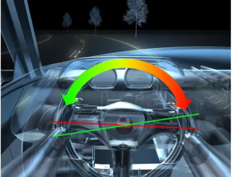
Additional support may also be providing a counter-steering torque with the electrically power assisted steering system (EPAS or EPS). The gently applied EPAS steering torque makes it harder to steer out (change lane without using the turn signal). The driver may still decide to change lane (without using the turn signal) and steer out from the lane by a stronger steering wheel movement or stay in the lane by gently steering back.
Figure 1.10. Counter-steering torque provided to support keeping the lane. (Source:
TRW)
The function works camera based by analysing the lane markings on the road in front and by comparing the current vehicle direction in relation to them. It usually incorporates hands-off detection of the steering wheel to avoid the use (misuse) of the system for autonomous driving.
Figure 1.11. Warning for misuse of lane assist for autonomous driving. (Source: Audi)
Another not safety but typical comfort function example is the parking assistant system which can cover the support level and furthermore the intervention level. Into the support level three functions can be enrolled:
parking space measurement, parking aid information and park steering information.
Figure 1.12. Parking space measurement (Source: Bosch)
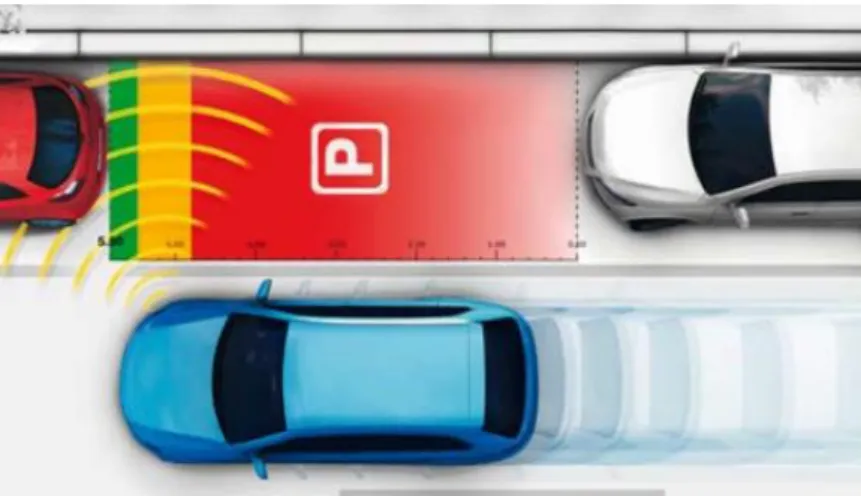
The parking aid information system monitors the close-up area in front and/or behind the vehicle by the ultrasonic sensors and informs the driver with an optical and/or acoustical signal of how close the vehicle is to an obstacle.
Figure 1.13. Principle of the operation of the parking aid systems (Source: Bosch)
When the parking space measurement is active the ultrasonic sensors are scanning the roadside. As soon as the system identifies a suitable parking space long enough for the car, the driver will be immediately informed. The driver can activate the parking assistant with a push of button and initiate the parking manoeuvre.
The park steering information system provides clear instructions on steering-wheel position and the necessary stop and switching points through a display, thus guiding the driver into the perfect parking position.
3.3. Intervention
The next level of driver assistance is the automated intervention into the vehicle control. Depending on the intervention scale there are categories of semi-automated driving and highly automated driving. While during semi-automated driving the vehicle‘s longitudinal movement is under automated control, as during highly automated driving both longitudinal and lateral control takes part of the vehicle motion.
3.3.1. Semi-automated intervention
Basically semi-automated driving can be described as supported driving plus longitudinal control of vehicle movement. The market currently offers several functions in this segment like adaptive cruise control (ACC) with Stop & Go extension or Emergency Brake Assist. This function uses a radar sensor to monitor the traffic
ahead adjusting vehicle speed and keeping safe distance to the vehicle in front via the throttle-by-wire and brake-by-wire intelligent actuators. While no front vehicle is detected speed control is active keeping constant vehicle speed regardless of the road inclination, but when a vehicle is detected ahead then distance control becomes active, keeping speed-dependant safe distance between the two vehicles. The following figure shows the moment when distance control becomes active.
Figure 1.14. ACC distance control function for commercial vehicles (Source: Knorr- Bremse)
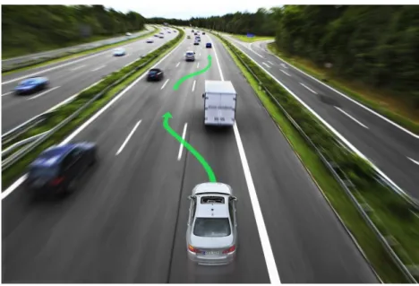
On top of ACC function there may be a collision avoidance (mitigation) option. Based on the radar signal (and video sensors), the system warns the driver if there is a collision hazard, and in case the collision is inevitable for the driver the system automatically applies the brakes to reduce vehicle speed, thus collision severity. Such function physically mitigates the collision consequences by reducing collision speed.
Figure 1.15. Steps of collision mitigation with an ACC System (Source: Toyota)
3.3.2. Highly automated intervention
The former levels of automated driving all had operational examples on the market, whereas highly-automated driving represents the state-of-the-art of road vehicle automation that soon (2016-2020) will be introduced to the public domain with function like Temporary Auto Pilot, Automated support for Roadwork and Congestion.
High automation means integrated longitudinal and lateral control of the vehicle enabling not only acceleration and braking for the vehicle automatically, but also changing lane and overtaking. Such functions will be introduced initially on motorways since they are the most suitable roads for automated driving; the road path has only smooth alterations (curves or slopes), they are highlighted by easily recognizable lane markings, protected by side barriers, and last but not least there is only one-way traffic. Potential use-cases are monotonous driving situations like traffic jams or long distance travel in slight traffic.
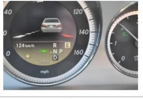
Temporary Auto Pilot function of Volkswagen [7] (developed within the EU funded HAVEit project) offers highly-automated driving on motorways with a maximum speed of 130 kilometres per hour. TAP provides an optimal degree of automation as a function of the driving situation, perception of the surroundings, the driver
and the vehicle status. TAP maintains a safe distance to the vehicle ahead, drives at a speed selected by the driver, reduces this speed as necessary before a bend, and keeps the vehicle in the centre of the lane by detecting lane markings.
Figure 1.16. Temporary Auto Pilot in action at 130 km/h speed (Source: Volkswagen)
The responsibility always stays by driver even he is temporarily gets out of the control loop. He acts as an observer when TAP is active and can take back the vehicle control from TAP any time in safety-critical situations. The vehicle can also give back control to the driver if the preconditions for enabling TAP are not met.
The driver is continuously monitored for drowsiness and attention by the vehicle to prevent accidents due to driving errors by an inattentive, distracted driver. The system also obeys overtaking rules and speed limits. Stop and start driving manoeuvres - for example in traffic jams - are also automated.
From time-to-market point of view a definitive advantage of the TAP system is that it has been realized on a relatively production-like sensors, consisting of production-level radar-, camera-, and ultrasonic-based sensors enhanced by a laser scanner and an electronic horizon. (Source: Volkswagen)
BMW demonstrated in 2009 that based on sensor fusion of eHorizon, GPS and samara information a vehicle can autonomously drive around a closed race circuit, following the ideal path. After the impressive performance BMW decided to introduce highly automated driving functions in series production vehicles until 2020. Aside typical functions like braking, accelerating and overtaking other vehicles entirely autonomously, the system will focus on challenges, like motorway intersections, toll stations, road works and national borders. The research prototype vehicle has run approximately 10,000 test kilometres up to now on public road with no driver intervention. (Source: [8])
Figure 1.17. Highly automated driving on motorways (Source: BMW)
Highly automated driving can also help in case of emergency, for example if biosensors detect that the driver is having a heart attack. The Emergency Stop Assistant function is able to switch the vehicle to highly automated driving mode and taking into account the traffic situation, manoeuvres the vehicle in a safe and controlled way to a standstill on the roadside. By switching on the hazard warning lights and making an eCall to request medical assistance, the situation is handled with maximum efficiently. (Source: [8])
Toyota has presented its AHDA [9] test vehicle in 2013 that incorporates highly automated driving technologies to support safer highway driving and reduce driver workload. AHDA combines two automated driving technologies together Cooperative-adaptive Cruise Control and Lane Trace Control. The vehicle is fitted with cameras to detect traffic signals, radars and laser-scanner to detect vehicles, pedestrians, and obstacles in the surroundings. Via sensor fusion the vehicle is also able to identify traffic conditions, like intersections and merging traffic lanes.
Figure 1.18. Test vehicle with automated highway driving assist function (Source:
Toyota)
In addition to radar based adaptive cruise control (ACC), Cooperative-adaptive Cruise Control (CCC) uses wireless communication between the vehicles to exchange vehicle dynamics data that enables smoother and more efficient control for maintaining a safe distance. Cooperative-adaptive Cruise Control uses 700-MHz band vehicle-to-vehicle ITS communications (V2V) to broadcast acceleration and deceleration data of the leading vehicle so that the following vehicles can control their speed profile correspondingly to better maintain inter- vehicle distance. Eliminating unnecessary accelerations and decelerations for the following vehicles results in better fuel efficiency and avoiding traffic congestion.
Lane Trace Control is a new assistance function that aids steering to keep the vehicle on an optimal driving path within the lane. It uses high-performance cameras, radar and sensor fusion to determine the optimal road path and provide smooth driving for the vehicle at all speeds. The system automatically intervenes in the steering, the drivetrain and the braking system when necessary to maintain the optimal path within the lane.
The objective of the automated assistance in road works and congestion function (developed within the EU funded HAVEit project) is to support the driver in overload situations like driving in narrow lanes of roadwork areas on motorways with lot of vehicles driving closely beside. Entering the road works and driving for longer distance in the road works area is very challenging for the driver. Some drivers even feel fear while other vehicles are driving so close in the parallel lane.
An integrated approach of the lateral and longitudinal control is used to adapt the speed and the lateral position of the vehicle to run the optimal path. (This assistance function will work at speeds between 0 and 80 km/h.) When the pre-conditions for the Automated Roadwork Assistance function are met the driver can switch to highly automated driving mode, taking his hands off the steering wheel. By this, the driver could drive through the road construction, without using his hands or feet. This guarantees that the driver gets the best possible support available, in particular with respect to lateral vehicle control.
Figure 1.19. Demonstrating automated roadwork assistance functionality. (Source:
HAVEit)
Another step in automation is the concept of platooning, which was motivated by intelligent highway systems and road infrastructure, see the PATH program in California and the MOC-ITS program in Japan. The European programmes were based on the existing road networks and infrastructure and focused mainly on commercial vehicles with their existing sensors and actuators. In a Hungarian project an automated vehicle platoon of heavy vehicles was developed. In a platoon system 5 to 10 vehicles are organized. The intervehicle spacing is small and constant at all speeds and vehicles. A well-organized platoon control may have advantages in terms of increasing highway capacity and decreasing fuel consumption and emissions. The control objective in platooning is to maintain vehicle following within the platoon and platoon stability under the constraint of comfortable ride. Since the desired intervehicle spacing is very small, the allowable position error is also small, which implies very accurate tracking of the desired spacing and speed trajectories. This accuracy puts constraints on the performance of the sensors and actuators as well as on the controller bandwidth.
Figure 1.20. Demonstration of a platoon control
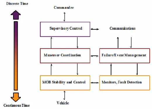
A three-layer software architecture that moves from discrete to continuous signals was in the PATH project, see Figure 20 and Figure 21. It should be noted that our design is not necessarily unique or optimal, but as a preliminary approach is sufficient to prove our point.
• The stability and control layer deals with continuous signals and interfaces directly with the platform hardware. It contains several dynamic-positioning algorithms, a thruster allocation scheme, and sensor data processing and monitoring for fault detection. Control laws are given as vehicle state or observation feedback policies for controlling the vehicle dynamics. The corresponding events are sent to the manoeuvre coordination layer.
• In the manoeuvre coordination layer control and observation subsystems responsible for safe execution of atomic manoeuvres such as assemble, split, wind tracking, and go to a location. Manoeuvres may include several modes according to the lattice of preferred operating modes. Mode changes are triggered by events generated by the stability layer monitors. It also monitors incidents and reacts to minimize their impact on manoeuvres and maximize safety.
• The supervisory control layer: control strategies that the modules follow in order to minimize fuel consumption and maximize safety and efficiency. Discrete commands are given to achieve high-level goals of overall coordination and manoeuvring of the mobile offshore bases. This layer monitors the evolution of the system with respect to global mission goals. It receives commands and translates them into specific manoeuvres that the platforms need to carry out.
Figure 1.21. Hierarchical structure applied in the PATH project
3.4. Full Automation
Until the driver has to be (legally) responsible for the behaviour of the vehicle, the driver will always be an integral part of the control loop. That is why full automation of public road vehicles is not realistic in the near future. There are some promising experiments on fully automated manoeuvring of vehicles but most of them are realized on a separated area and are far from being able to adapt on public roads without an intelligent, independent road infrastructure.
Distinguished members of IEEE, the world‘s largest professional organization dedicated to advancing technology for humanity, have selected autonomous vehicles as the most promising form of intelligent transportation, anticipating that they will account for up to 75 % of cars on the road by the year 2040, see [10].
The U.S. government also supports the autonomous car research, as keeping it the next evolutionary step in technology. In Nevada, Florida and California it is licensed to test vehicles without a driver, which is used by Google as getting the first self-driven car license in Nevada in 2012. (Source: [11])
Figure 1.22. Google’s self-driving test car, a modified hybrid Toyota Prius (Source:
http://www.motortrend.com)
Google gathered the best engineers from the DARPA Challenge series, which was a legendary competition for American autonomous vehicles. It was started in 2004, funded by the Defense Advanced Research Projects Agency, which is a research institute of United States Department of Defense. Three events were held in 2004, 2005 and 2007 regarding to the autonomous passenger cars. The 2012 event has focused on autonomous emergency-maintenance robots.
Google‘s self-driving car use video cameras, radar sensors and a LIDAR (see Section 3) for environment sensing, as well as detailed maps for navigation. The car is supported by the Google‘s data centres, which can process the information gathered by the test cars when mapping the terrain. (Source: [12])
The main vehicle manufacturers are also heading toward the autonomous solutions, but they are trying to reach the goal step-by-step, and not at once like Google. They are developing (in cooperation with their OEMs) such subsystems which can increase the automation level of the car, and also can be marketed in production vehicles as new driver assistance systems. An example of this attitude can be found in an interview with Daimler head of development Thomas Weber, who said "Autonomous driving will not come overnight, but will be realized in stages". The plans to start selling self-driving cars is about 2020, primarily in North America. (Source: [13])
Chapter 2. Layers of integrated vehicle control
Conventionally, the control systems of vehicle functions to be controlled are designed separately by the equipment manufacturers and component suppliers. One of the problems of independent design is that the performance demands, which are met by independent controllers, are often in interaction or even conflict with each other in terms of the full vehicle. As an example braking during a vehicle manoeuvre modifies the yaw and lateral dynamics, which requires parallel steering action or, as another example, under/over steering requires parallel braking intervention. The second problem is that both hardware and software will become more complex due to the dramatically increased number of sensors and signal cables and these solutions can lead to unnecessary hardware redundancy.
The demand for the integrated vehicle control methodologies including the driver, vehicle and road arises at several research centres and automotive suppliers. The principle of integrated control with the CAN network was presented by Kiencke in [14]. The purpose of integrated vehicle control is to combine and supervise all controllable subsystems affecting vehicle dynamic responses. An integrated control system is designed in such a way that the effects of a control system on other vehicle functions are taken into consideration in the design process by selecting the various performance specifications. Recently, several important papers have been presented in this topic, see e.g. [15][16][17][18][19].
1. Levels of intelligent vehicle control
The complex tasks of a vehicle control must be structured in a way that the logical steps are built on one another and the complexity can be simplified by abstracting substructures. The levels of intelligent vehicle control defined by Prof. Palkovics [20] is suitable to provide a general overview of the subject, later the different layers of intelligent vehicle control are described in a way they depend on each-other.
Figure 2.1. Levels of intelligent vehicle control (Source: Prof. Palkovics)
1.1. Electronic System Platform
The bottom level, the ―Electronic System Platform― solutions contain all the necessary building elements that are required for building up an electronically controlled vehicle system. This includes basic electronic and mechatronic hardware components like sensors and actuators, includes ECUs, but also software components like operating systems, diagnostics software, peripheral drivers and so on. The platform characteristics lies behind the fact that these individual components, building block can be used widespread in different makes and vehicle types, resulting in high production volume, thus reliable design and low costs.
1.2. Intelligent Actuators
The second level, the ―Intelligent Actuators― are the electronically controllable separate five main units of the vehicle drivetrain, namely the engine, transmission, suspension, brake system and the steering system. These main units are individual intelligences meaning that each unit has its own ECU with sophisticated functionality for electronic control in itself having communication links (CAN, FlexRay) to other ECUs for interaction, but one ECU is only responsible for the control of one unit. Typical characteristics of the intelligent actuators are having a dedicated interface for the electronic control of the whole unit. This is why they are often called as „by- wire― systems, meaning that there is no mechanical connection for the control. In this case these units are referred as drive-by-wire, shift-by-wire, suspension-by-wire, brake-by-wire abs last but not least steer-by-wire systems in a vehicle. These actuators are ―must have‖ components for the intelligent vehicle control.
1.3. Integrated Vehicle Control
In the next level, in the ―Integrated Vehicle Control‖ there is a harmonized control of the intelligent actuators (instead of individual control) on a vehicle level. This layer has an influence on the whole vehicle motion.
Maybe it is not trivial, but it is easy to understand what synergies become available in cases of harmonized or in other words integrated control of the intelligent actuators. The most obvious example is the integrated control of the brake and steering system, where the harmonized control could result in a significantly shorter brake distance. Let us imagine a so called u-split situation, where the road surface is divided into two parts based on a longitudinal separation. In this case the vehicles left hand side wheels (front left, rear left) are running on a hi-u surface e.g. u=0,8, while the right hand side wheels (front right, rear right) are running on a low-u surface e.g.
u=0,1. In this case there is a great potential for synergy when the brake system realizes the u-split situation and instead of using ―select-low‖ strategy – meaning that the lower u surface determines the maximum brake force on each sides – uses the maximum allowable braking force on each side with the help of the steering system providing compensating yaw torque to stabilize the vehicle direction.
1.4. Direct V2V, V2I Interactions
The fourth levels called ―Direct V2V, V2I Interactions‖ where ad-hoc direct vehicle-to-vehicle (V2V) communications and ad-hoc direct vehicle-to-infrastructure (V2I) communications support the vehicle and its driver to be able to carry out the control task, safely and economically. The control is based on the relative position of the other vehicles or the elements of the infrastructure. The simplest example of these interactions is the Adaptive Cruise Control (ACC) function, where the distance and the velocity of the following vehicle is determined by a radar system, establishing ad-hoc direct V2V connection between the ego and the following vehicle. The ACC function is (currently) limited to the longitudinal direction, but such communication interactions can be established also in the lateral direction for e.g. automated trajectory planning. A currently market available example for ad-hoc direct V2I interaction is the automatic traffic sign recognition function.
1.5. Control of Vehicle Groups and Fleets
Last but not least there is the fifth level with ―Control of Vehicle Groups and Fleets‖. This layer covers the control of a whole vehicle flow or a partial set of the vehicles, where the grouping is based on either the current location or on the vehicle ownership (fleets).Good example for the location based selection of the vehicle groups is the control of a road cross section or the so called platooning, where an ad-hoc virtual road train is formulated on a highway. Transportation fleets are generally controlled via a centralized informatics system, where current market availability is rather logistics, delivery control and vehicle operation related information acquisition (FMS, Telematics) than remote movement control of the vehicles.
The above described structuring of the intelligent vehicle control is rather system oriented while the following part will mostly concentrate on the internal control structure of a vehicle.
2. Layers of vehicle control
For achieving an integrated control a possible solution could be to set the design problem for the whole vehicle and include all the performance demands in a single specification. Besides the complexity of the resulting problem, which cannot be handled by the existing design tools, the formulation of a suitable performance specification is the main obstacle for this direct global approach. In the framework of available design techniques formulation and successful solution of complex multi-objective control tasks are highly nontrivial.
From control design point-of-view the integrated vehicle control consists of five potentially distinct layers[16]:
1. The physical layout of local control based on hardware components, e.g. ABS/EBS, TCS, TRC, suspension.
2. Layout of simple control actions, e.g. yaw/roll stability, ride comfort, forward speed.
3. The connection layout of information flow from sensors, state estimators, performance outputs, condition monitoring and diagnostics.
4. The layout of control algorithms and methodologies with fault-tolerant synthesis, e.g. lane detection and tracking, avoiding obstacles
5. Layout of the integrated control design.
Research into integrated control basically focuses on the fifth layers; however the components of any integration belong to the third and fourth layer. The components in the first two layers are assumed to exist. Note, that to some extent the layers may be classified by the degree of centralization, e.g. centralized, supervisory or decentralized.
During the implementation of the designed control algorithms additional elements from information technology and communication will be included in the control process. In the classical control algorithms a lossless link is assumed to exist between the system and control these algorithms are concerned mostly with delays, parametrical uncertainties, measurement noise and disturbances.
The performance of the implemented control is heavily affected by the presence of the communication mechanism (third layer), the network sensors and actuators, distributed computational algorithms or hybrid controllers. It is useful to incorporate knowledge about the implementation environment during the controller design process, for example dynamic task management, adaptability to the state (faults) of sensors and actuators, the demands imposed by a fault tolerant control, the structural changes occurring in the controlled system.
From architectural design point of view the model based simulation of the planned architecture provides an early stage feedback about the potential bottlenecks in the design [21][22]. Early stage simulation can reveal hidden mistakes that could turn out only after system implementation. When modification should be made on the implemented system due to the results of the safety analysis, it has much higher costs. The simulation based analysis needs lower costs, but takes time to prepare and carry out the simulations. The main advantage is that the simulation based analysis can be carried out from the early stage of the development. Certainly at the beginning of a system development, the system architecture is in its initial stage; therefore simulation model may also be inaccurate. The system design engineering and the safety engineering are parallel processes; the system model for the safety simulations is getting more and more accurate during the development. And there is a continuous feedback from the safety engineering to the system design engineering [23][24].
Figure 2.2. Initial model of the HAVEit architecture simulation
The software technology is not simply a software implementation of the control algorithm. The implementation and the software/hardware environment are also a dynamic system, which has an internal state and which
respond to inputs and produces outputs. If the actual plant is combined with an embedded controller through the sensor and actuator dynamics, a distributed hybrid system is created. With this approach the control design is closely connected with software design. The control design is evolving through the development of hybrid optimal control, observability/controllability analysis, and software design is being facilitated by distributed computing and messaging services, real-time operating systems and distributed object models.
In the different prototype implementation of autonomous or highly automated vehicles a strictly defined layer structure can be observed that definitely corresponds to the above mentioned layer structure even if some layers are merged together for simplicity. The following figure shows the PEIT approach of the vehicle control layer structure[25]:
Figure 2.3. Levels of intelligent vehicle control (Source: PEIT)
The PEIT architecture differentiates 3 different layers, namely the PEIT application layer, the powertrain interface and the integrated powertrain layer. The integrated powertrain layer contains 4 intelligent actuators, the drive-by-wire, the shift-by-wire, the brake-by-wire and the steer-by-wire systems. Important to notice that in the PEIT architecture the engine and transmission actuators are single subsystems, while the brake and steering systems are redundant subsystems. This is due to the requirement of availability based on the safety critical categorization of the subsystems. In case of the engine there is no backup function, in case of a transmission system there is only a ―limp home‖ function which serves as a limited (e.g. one fixed gear) but useful functionality to maintain the movability of the vehicle. When it comes to the brake or the steering system it is obvious that any malfunction can result in serious consequences, so these systems must be designed in a way that they tolerate at least one failure. This is why safety critical systems have fault-tolerant architecture. There are different possible realizations of a fault tolerant system, one is simply using redundancy. In this case there are two parallel system elements that work simultaneously and in case of a failure one system can take over the control from the broken one. There is also a redundant powertrain controller can be found in the integrated powertrain layer, further dividing the layer into 2 sublayers. Referring back to the Prof. Palkovics the powertrain controller implements the vehicle level control, while the by-wire systems underneath are the intelligent actuators.
Figure 2.4. HAVEit System Architecture and Layer structure (Source: HAVEit)
The HAVEit layer structure [6] is a further optimized, extended and structured architecture, where there are basically two main layers, namely the command layer and the execution layer. The interface in between is specifically called the ―motion vector‖. Even if there are a lot of other functions involved, the basic idea is that the command layer specifies the motion vector, which has to be followed by the vehicle that is carried out by the execution layer.
2.1. Command layer
The command layer contains the high level algorithms for the longitudinal and the lateral control of the automated vehicle. The command layer calculates the desired acceleration and direction and communicates the results to the powertrain via the powertrain interface, which also provides feedback about the vehicle state for the high level control.
Based on the driver intention and the information coming from the perception layer the command layer defines the vehicle automation level and calculates the vehicle trajectory. The objective of the perception layer is to collect information about the external environment and the vehicle, thus providing information about vehicle status and objects in the surrounding environment. From this information the command layer determines the obtainable levels of vehicle automation and displays the options to the driver. Meanwhile the co-pilot calculates possible vehicle trajectories and prioritizes them based on the accident risk. The driver selects the desired level of vehicle automation from the available options via the HMI. Finally the mode selection unit decides the level of automation and selects the trajectory to be executed.
2.2. Motion Vector
The motion vector acts as an interface between the command layer and the execution layer. It is bidirectional, delivering longitudinal and lateral control commands to the powertrain and providing vehicle status feedback information for the higher level control.
This middle layer contains predefined data transfer for the control and the feedback of the powertrain. It includes commands for the vehicle control including the desired status of the powertrain and the required acceleration and torque. This interface also includes status feedback from the powertrain to the application layer providing important information whether the control action resulted in the required movement.
2.3. Execution Layer
The execution layer contains a full drivetrain control connected to intelligent actuators via a high speed communication network. As the implementation of a fully electronic interface (motion vector) for controlling the powertrain enables the replacement of the human driver for an electronic intelligence (auto-pilot), the execution layer cannot distinguish whether the commands are originated from a human driver or an auto-pilot.
The commands are coming through the same interface, so the execution layer has to execute only. Considering that there are safety critical subsystems can be found among the intelligent actuators a fault-tolerant architecture
is a prerequisite. This fault tolerant architecture not only includes duplicated powertrain controllers, steering and braking systems but also a redundant communication network, power supply and HMI to the driver. The following figure shows the powertrain control structure of the execution layer in the PEIT demonstrator vehicle[25].
Figure 2.5. Powertrain Control Structure of the execution layer (Source: PEIT)
3. Integrated control
Conventionally, the control systems of vehicle functions to be controlled are designed separately by the equipment manufacturers and component suppliers. One of the problems of independent design is that the performance demands, which are met by independent controllers, are often in interaction or even conflict with each other in terms of the full vehicle. As an example braking during a vehicle manoeuvre modifies the yaw and lateral dynamics, which requires steering action or, as another example, under/oversteering requires braking intervention. The second problem is that both hardware and software will become more complex due to the dramatically increased number of sensors and signal cables and these solutions can lead to unnecessary hardware redundancy.