[AUTHOR NAME]Shaban A, Telegdi J, Felhősi I, Molnár-Vörös N 1
Chapter: 16. Functional thin films and nanostructures for sensors
Shaban Abdul1, Telegdi Judit1,2, Felhősi Ilona1, Nikoletta Molnár1
1Research Centre for Natural Sciences, Hungarian Academy of Sciences, Bp., Hungary.
2Óbuda University, Budapest, Hungary
This chapter covers the description of different sensor types, transducers, transducing principles, preparations and characterization methods of nanostructured materials, as well as applications of functional thin films and nanostructured materials in sensing.
16.1. Introduction to sensors
The fast developments in the field of materials science, particularly nanoscience, have been significant drivers in the progress of sensor technologies. For instance, the high resonance stability of single-crystal quartz, as well as its piezoelectric properties, has made possible an extraordinarily wide range of high performance, affordable sensors that have played an important role in everyday life and national defense. More recently, a new era in sensor technology was the applications of new nanoscale structured materials, creating new approaches for transducing physical phenomena into electrical output that can be readily processed by a computer.
Ongoing developments in the immobilization of nanostructured materials on transducers will permit improved sensing properties and behavior, thereby offering possibilities for new sensors with innovative features, such as greater fidelity, economical advantage and improved reliability.
Modern sensors produce a voltage out-put or a digital signal that indicates the changes of the measured physical variable. Those output signals are often imported into computer programs, stored in files, plotted on computers and analyzed for end-users.
In spite of the widespread published literature on the detailed sensor technology; significant ambiguity exists in sensor definition and classification, one based on properties sensed and the other on technologies used.
Sensor Classification
Sensors are classified in many schemes that range from simple formula to complex. A practical possible classification method of sensors considers all sensor properties, such as stimulus, specifications, physical phenomenon, conversion mechanism, material, and application field.
[AUTHOR NAME]Shaban A, Telegdi J, Felhősi I, Molnár-Vörös N 2 Other classification methods for sensors include physical or chemical effect/transduction principle; measured primary input variable, material of the sensor element, applications cost;
accuracy, and output signal domain.
16.2. Types of Sensors
One of the ways of classifying sensors is based on the output signals. Most applied sensor types that can be associated with their capability are listed as:
Magnetic parameters: Magnetic moment, magnetic flux density, etc.
Mechanical properties: Strain, stress, torque, flow, length, force, pressure, acceleration, etc.
Thermal characters: Flux, thermal conductivity, heat flow, specific heat, temperature, etc.
Electrical characteristics: Conductivity, voltage, resistance, charge, current, inductance, etc.
Optical properties: Refractive index, reflectivity, polarization, light intensity, wavelength, etc.
Acoustic properties: Wave characteristics (amplitude, phase polarization), spectrum, wave velocity, etc.
Biological/Chemical properties: pH, concentration of gaseous species in the environment, additives or constituents in liquid, etc.
Among these, electrochemical sensors have more advantages because the electrodes can sense the materials, which are present within the host without doing any damage to the host system.
16.2.1. Chemical sensors
Chemical sensors are those devices that detect and convert chemical information (such as concentration, pressure, activity of particles) into an electrical signal to obtain qualitative or quantitative time- and spatial-resolved information about specific chemical components.
Chemical sensors may be classified according to the different sensor properties used for the particle detection. Most commonly used characteristics are conductivities, potentials, capacities, heats, masses, or optical constants, which change upon variations in the composition of chemical species interacting with the sensor (Grandke and Ko, 1991). Huge variety of chemical sensors exists in the market. Typical examples of commonly used chemical sensors are the follows:
[AUTHOR NAME]Shaban A, Telegdi J, Felhősi I, Molnár-Vörös N 3 amperometric CO-sensor based upon current measurements in liquid electrolytes to monitor air quality; the Lambda-probe which is based upon potential measurements using solid electrolytes to detect oxygen in the car-exhaust; the Taguchi SnO sensor measures the conductance of the oxides to detect reducible gases in gas warning systems; the pellistors based upon measurements of reaction heats using oxide catalysts to monitor reducible gases; the pH-sensitive electrode follows the change in potential, etc.,
The high selectivity and quantitative detection of chemical species is usually not required to sensors. In contrast to the precise chemical analytical laboratory equipments, the detection of chemical species with chemical sensors is usually less selective but these devices can have small dimensions and are comparatively cheap.
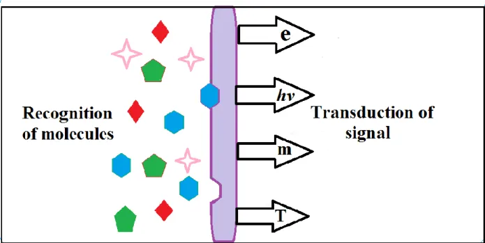
Thin films and nanostructures play an increasingly important role in state-of-the-art sensors and actuator technologies, both as transducers (functional materials) and structural materials. Micro- electromechanical (MEM) systems provide a good example of the growing use of materials confined to submicron dimensions to fulfill numerous and versatile functions in advanced devices. A schematic diagram shows the chemical sensor in Fig. 16.1
Figure 16.1 Schematic diagram of a chemical sensor.
[AUTHOR NAME]Shaban A, Telegdi J, Felhősi I, Molnár-Vörös N 4 16.2.2. Electrochemical sensors
Chemical sensor provides a certain type of response directly related to the quantity of a specific chemical species. All chemical sensors consist of a transducer, with transforms the response into a detectable signal on modern instrumentation, and a chemically selective layer, which isolates the response of the analyte from its immediate environment. They classification happens according to the property to be determined as: electrical, optical, mass or thermal sensors and they are designed to detect and respond to an analyte in the gaseous, liquid or solid state.
Compared to optical, mass and thermal sensors, electrochemical sensors are especially attractive because of their remarkable detect-ability, experimental simplicity and low cost. There are three main types of electrochemical sensors: potentiometric, amperometric and conductometric.
Potentiometric sensors are defined as a zero-current technique that measures the potential across the interface (often a membrane). Such sensors are ion selective electrodes with broad application field such as medical chemistry, water monitoring, environmental toxicity. There are three basic types of potentiometric devices: ion-selective electrodes (IES), coated wire electrodes (CWES) and field effect transistors (FETS).
Voltammetric sensors are based on electroanalytical method, measuring the current-potential function information about the analyte. Carbon based electrodes are widely used for voltammetric studies, due to its stability, reproducible surface preparation, wide and stable double layer capacitance potential range and ability to easily modify the surface by functional layers.
Amperometric sensors are based on the monitoring of current in time at constant applied potential. The charge measured in current can be directly related to the concentration of analyte.
This sensing method is commonly employed in biosensors and chemical sensors. Cyclic voltammetry is one of the most widely used electrochemical methods, which is useful to obtain information about the redox potential and electrochemical reactions of reducible or oxidizable analyte. More precise detection of electroactive analyte may be done with differential pulse voltammetry, where a pulse of constant amplitude is modulated on top of a potential scan and the current is sampled just before and at the end of the modulation pulse, recording the difference as the result. Obtained waves resemble the first derivative of a sampled dc scan, thus a peak.
[AUTHOR NAME]Shaban A, Telegdi J, Felhősi I, Molnár-Vörös N 5 Conductivity sensors are based on the monitoring the change of electric conductivity of a film, which affected by the presence of analyte. Conductivity methods are typically non-selective.
Thin films of oxides or inorganic films are used mostly as gas sensors; as chemisorption of gas molecules on the surface changes the conductivity of the film.
Immobilization of chemical microstructures onto electrode surfaces has been a major progress area in electrochemistry in recent years. Chemically modified electrodes (CME) result from a deliberate immobilization of a modifier agent onto the electrode surface through chemical reactions, chemisorption, composite formation or polymer coating. Compared to conventional electrodes, more specific control of electrode characteristics and reactivity is accomplished by surface modification, since the immobilization transfers the physicochemical properties of the modifier to the electrode surface (Stradiotto et al., 2003).
16.2.3. Optical sensors
Optical sensors are devices that transform light waves into electronic signals. Optical sensors are generally based either on measuring the magnitude of an intensity variation in one or more light beams or it analyzes the phase changes in the light beams that interact or interfere with one another. Thus, sensors belonging to this category are termed either intensity sensors or interferometric sensors. The advantage of the optical sensors, in comparison to conventional types, is the capacity of optical fibers that send and receive optical signals over long distances.
16.2.4. Biosensors
A biosensor is an analytical device, which transforms a biological modification into a measureable and processable signal. Biosensors consist of a biological component (biochemical receptor) coupled to a transducer that will convert the biological into an electrical signal. A biological molecule, like an enzyme or cells, tissue slice, organelle, peptide, antibody, nucleic acid etc., guarantees molecular recognition and may transform the analyte in some manner. The electrochemical transducer (potentiometric, amperometric or conductometric) displays the change in properties. The choice of transducer depends on the biological reaction. Molecular recognition could be accompanied by chemical conversion of the analyte to its products, which are determined by the biocatalytic sensor. In other cases, when an antibody is used, the bio- specific recognition systems and interactions take place without analyte conversion, resulting in an affinity sensor.
[AUTHOR NAME]Shaban A, Telegdi J, Felhősi I, Molnár-Vörös N 6 Combination of nanotechnology and bioelectronics has revealed new possibilities to miniaturize and to optimize microscale devices at nanoscale. It makes possible to measure specific electrical properties more accurately in combination with various electrochemical transducers. The higher surface-to-volume ratio of nano-objects makes their electrical properties increasingly susceptible to external influences, especially as these structures continue to shrink toward the atomic limit (Grieshaber et al., 2008). Since the nanometer dimension of these objects are comparable with the size of the target biomolecules, higher measurement sensitivity may be accomplished, and the sensitivity may also increase due to higher capture efficiency. Nanostructures already represent important new components in recently developed electrochemical biosensors, like the use of nanoparticles as electrochemical labels for DNA sensing (Merkoci, 2007; Park et al., 2002).
Nanowires, carbon nanotubes, nanoparticles and nanorods are merely some of the familiar objects that are emerging as candidates to become crucial elements of future bio-electronic devices and biosensors (Wanekaya et al., 2006; Stadler et al., 2007).
16.3. Sensors and signal processing.
16.3.1. Sensors and transducers
Devices which implement an “Input” function are commonly termed as sensors since they
“sense” a physical alteration in some characteristic that alter in response to some excitation, for example force or heat and covert that into a usable electrical signal. Devices, which perform an
“Output” function are generally called actuators and are applied to regulate some external device, for example displacement or sound. Measurement systems involve sensors, transducers actuators and signal processing instruments. The sensor output is usually an ‘electrical quantity’
and the measurand is a ‘physical quantity, property or condition which is to be measured’.
Transducer
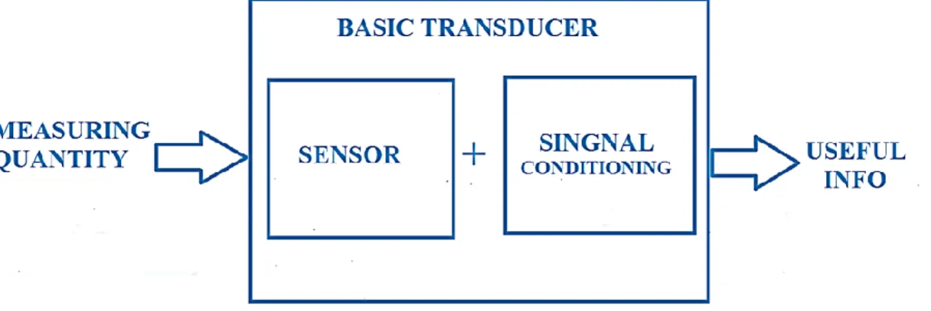
A transducer is an element, which converts a specified measurand into a usable output by using a transduction principle (Grandke and Ko, 1991). Another useful definition is: a transducer device is that converts a signal from one form of energy to another form. A transducer consists principally of two main mechanisms:
[AUTHOR NAME]Shaban A, Telegdi J, Felhősi I, Molnár-Vörös N 7
Sensing element: the physical quantity or its rate of change is sensed and responded to by this part of the transistor.
Transduction element: the output of the sensing element is passed on to the transduction element. This element is responsible for converting the non-electrical signal into its proportional electrical signal.
Even though there is no thoroughly acknowledged difference between sensors and transducers, the word sensor is mostly used when there is an electrical output signal (as shown by Fig. 16.2).
Figure 16.2. Transducer blocks diagram showing the sensing and transduction elements.
On the other hand, a detector could be used in cases when non-quantitative measurements are required but in this case an input signal obtained is only the sensitivity (Grandke and Ko, 1991). There may be cases when the transduction element performs the action of both sensing and transduction. The best example of such a transducer is a thermocouple. A wire (copper-nickel 55-45% alloy) can be termed as a sensor since variation in mechanical displacement (tension or compression) can be sensed as change in electric resistance.
Transducer specifications
Transducers, measurement systems in general, are not perfect systems. Frequently sensors incorporate more than one transduction principle; therefore, sensors can be classified simply by their input energy form or signal domain of interest. Sensor specifications are a number of parameters related to performance that inform the end-user about deviations from the ideal
[AUTHOR NAME]Shaban A, Telegdi J, Felhősi I, Molnár-Vörös N 8 behavior of the sensors. In the following one can see the numerous specifications of a sensor/transducer structure (Fortin, 2009):
Range: The range of a sensor indicates the boundaries between which the input can vary.
Span: The span is a value difference between the maximum and minimum limits of the input.
Error: Error is the difference between the measured and the true value of the input.
Accuracy: The accuracy describes how near are the measured result to the actual value of the measurand (expressed as a percentage of the full range output).
Sensitivity: it is defined as the ratio of change in output value of a sensor to the per unit change in input value that causes the output change.
Nonlinearity: the nonlinearity designates the maximum deviation of the actual measured curve of a sensor from the ideal curve. Linearity is often specified in terms of percentage of nonlinearity.
Hysteresis: it is an error of a sensor, which is defined as the maximum difference in output at any measurement value within the sensor’s specified range when approaching the point first with increasing and then with decreasing the input parameter.
Resolution: is the smallest detectable incremental change of input parameter that can be detected in the output signal. Resolution can be expressed either as a proportion of the full-scale reading or in absolute terms.
Stability: it is the capability of a sensor device to provide same output when used to measure a constant input over a period of time. Usually the deviation of the measurement is called ‘drift’.
Dead band/time: the dead band or dead space of a transducer is the range of input values for which there is no output. The dead time of a sensor device is the time duration from the application of an input until the output begins to respond or change.
Repeatability: It specifies the ability of a sensor to give identical output for recurring measurements of the same input value (stated as a percentage of the full range output).
Response time: it describes the rapidity of alteration in the output on a step-wise variation of the measurand.
16.3.2. Signal conditioning of sensors
Transducers sense physical phenomenon and transform the measurand into an electrical signal.
However, these signals possibly will not be in their proper forms. Signals given by a transducer
[AUTHOR NAME]Shaban A, Telegdi J, Felhősi I, Molnár-Vörös N 9 could be nonlinear or noisy. Therefore, before conveying these signals, it is crucial to eliminate the noise and nonlinearity related to the output from a sensor or a transducer. It is also desirable to adjust the amplitude (high/low) to the desired (analogue/digital) form of the produced signals into adequate limits and form. These activities are accomplished by a process designated as
‘signal conditioning’. Signal conditioning process affects output signal from a sensor in several ways (Grandke and Ko, 1991):
To protect the sensor elements from any damage from high current or voltage signals.
To convert the output signal from a transducer into the predicted form i.e. voltage/current.
To amplify or attenuate the signals to an acceptable level for the next element.
To eliminate noise from a signal.
To manipulate the signal from its nonlinear form to a linear one.
To deliver any useful signal, a sensor output signal needs to be amplified with an amplifier that has a voltage gain up to 104 and a current gain up to 106.The amplification of a linear signal with the output signal is an exact reproduction of the input, just changed in amplitude, thus amplification is part of signal conditioning. When using analogue sensors, generally some form of amplification (Gain), impedance matching, isolation between the input and output or perhaps filtering (frequency selection) may be required before the signal can be used; this is conveniently performed by operational amplifiers (OP).
In addition, when measuring very small physical changes the output signal of a sensor can become “contaminated” with undesirable signals or voltages that prevent the actual signal required from being measured properly. These unwanted signals are called “noise “. This noise or interference can be either significantly reduced or even eliminated by using signal conditioning or filtering techniques.
By using either a low pass (LP) or a high pass (HP) or even band pass (BP) filter, the
“bandwidth” of the noise can be reduced enormously, and only the required output signal is left.
Both amplification and filtering play a significant role in interfacing both sensors and transducers to microprocessor and electronics based systems in “real world” conditions. Increasing the signal-to-noise ratio is usually performed by taking several measurements (data) and then averaging them to obtain the final value.
[AUTHOR NAME]Shaban A, Telegdi J, Felhősi I, Molnár-Vörös N 10 16.3.3. Transduction principles
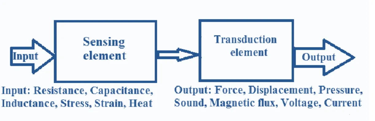
As previously mentioned transduction is taking energy from one form and transferring it into another one and quantifying the energy change or energy input. There are a number of measurands that can be quantified via a variety of different transduction techniques. Multiple transduction approaches are utilized to quantify a measurand thus requiring the understanding of the specifications in order to make a suitable selection. A schematic diagram of the sensing system (sensing and transducing elements) is shown in Fig. 16.3.
Figure 16.3. Scheme of a sensor system consisting of input, sensor and transducer and output elements.
Transduction principles can be categorized according to the form of energy the sensor signals are received and generated as explained by Lion (1969). The most common transduction principles are listed, that reveale some interesting complexities (Grandke and Ko, 1991; Gimzewski et al., 1994). An illustration of a self-generating sensor is a piezoelectric pressure sensor where the mechanical energy form (strain or pressure) generates electrical signal which is an attribute of the fundamental material behavior of the sensor element.
Principles of energy transformation by transducers
The most common fundamental transduction principles used in sensors are classified as (Fortin J., 2009):
1. Passive type transducers a. Resistance variation type
Resistance strain gauge – The change in value of resistance of metal semi-conductor due to elongation or compression is known by the measurement of torque, displacement or force. This principle finds wide application due to its excellent accuracy in measuring the
[AUTHOR NAME]Shaban A, Telegdi J, Felhősi I, Molnár-Vörös N 11 change in displacement occurred and converting it into its corresponding value of resistance, inductance or capacitance (Hierlemann et al., 2009).
Resistance thermometer – The change in resistance of metal wire is due to the change in temperature known by the measurement of temperature.
Resistance hygrometer – The change in the resistance of conductive strip due to the change of moisture content is known by the value of its corresponding humidity.
Hot wire meter – The change in resistance of a heating element due to convection cooling of a flow of gas is known by its corresponding gas flow or pressure.
Photoconductive cell – The change in resistance of a cell due to a corresponding change in light flux is known by its corresponding light intensity.
Thermistor – The change in resistance of a semi-conductor that has a negative co- efficient of resistance is known by its corresponding measure of temperature.
Potentiometer type – The change in resistance of a potentiometer reading due to the movement of the slider as a part of an external force applied is known by its
corresponding pressure or displacement.
b. Capacitance variation type
Variable Capacitance Pressure Gauge – The change in capacitance due to the change of distance between two parallel plates caused by an external force is known by its
corresponding displacement or pressure.
Dielectric Gauge – The change in capacitance due to a change in the dielectric is known by its corresponding liquid level or thickness.
Capacitor Microphone – The change in capacitance due to the variation in sound pressure on a movable diagram is followed by its corresponding sound.
c. Inductance variation type
Eddy current transducer: The change in inductance of a coil due to the proximity of an eddy current plate is known by its corresponding displacement or thickness.
Variable reluctance type: The variation in reluctance of a magnetic circuit that occurs due to the change in position of the iron core or coil is known by its corresponding
displacement or pressure.
[AUTHOR NAME]Shaban A, Telegdi J, Felhősi I, Molnár-Vörös N 12
Proximity inductance type: The inductance changes of an alternating current excited coil due to the change in the magnetic circuit is known by its corresponding pressure or displacement.
Differential transformer: The change in differential voltage of two secondary windings of a transformer because of the change in position of the magnetic core is known by its corresponding force, pressure or displacement.
Magnetostrictive transducer: The change in magnetic properties due to change in pressure and stress is known by its corresponding sound value, pressure or force.
d. Voltage and Current Type
Photo-emissive cell: Electron emission due to light incidence on photo-emissive surface is known by its corresponding light flux value.
Hall-effect: The voltage generated due to magnetic flux across a semi-conductor plate with a movement of current through it is known by its corresponding value of magnetic flux or current.
Ionization chamber: The electron flow variation due to the ionization of gas caused by radio-active radiation is known by its corresponding radiation value.
2. Active type transducers
Photo-voltaic cell: The voltage change that occurs across the p-n junction due to light radiation is known by its corresponding solar cell value or light intensity.
Thermopile: The voltage change developed across a junction of two dissimilar metals is known by its corresponding value of temperature, heat or flow.
Moving coil type: The change in voltage generated in a magnetic field can be measured using its corresponding value of vibration or velocity.
Piezoelectric type: When an external force is applied on to a quartz crystal, there will be a change in the voltage generated across the surface. This change is measured by its corresponding value of vibration. Piezoelectric transducer can measure pressure, mass, force or acceleration similarly. For low-pressure measurement, possible vibration should be compensated. Due to its excellent frequency response, it is normally used as an essential part of the quartz crystal microbalance (QCM), where mass variations can be detected by frequency changes. An important example for the transducer that uses the
[AUTHOR NAME]Shaban A, Telegdi J, Felhősi I, Molnár-Vörös N 13 piezo-resistive effect is a silicon-based MEMS pressure sensor. In microsensors, piezoelectric materials can be either straight deposited onto the element or integrated into it, for instance, with lamination of a piezoelectric polymer film (Fortin, 2009).
Typical piezoelectric crystal materials include LiNbO3, LiTaO3, Li2 B4O7, GaAs, and quartz. Typical thin film-based piezoelectric materials include ZnO, AlN, and lead- zirconate titanate (Pb(Zr,Ti)O3) (PZT). PZT is probably the most widely used piezoelectric material for sensing in applications such as accelerometers, vibration measurement, ultrasound, etc. (Valentini et al., 2004). Because PZT has an order of magnitude higher piezoelectric effect than ZnO and AlN, many techniques have been developed to integrate PZT with a micro-device, including sol-gel and sputtering techniques. ZnO and AlN films have also been integrated into micro-devices for the purpose of transduction (Valentini et al., 2004; Ried et al., 1993; Ko et al., 2003).
The advantages of the piezoelectric transducer are:
1. very high frequency response,
2. no need for external power supply (self-generating),
3. simplicity of use (small dimensions and large measuring range), 4. made in any desired shape and form, and,
5. a large dielectric constant.
On the other hand, the disadvantages of this transducer are the follows: It is not suitable for measurement in static condition; they need high impedance cable for electrical interface because the device operates with small electric charge; the output may vary according to the temperature variation of the crystal (depends on the crystal cut); the output is largely affected by relative humidity variations, which demands coating the crystal with polymer material.
There are many ways to convert a change in an external measurand into a change in an electrical signal directly, particularly in a MEMS device, where there are moving parts that can be accessed electrically or integrated in thin films that often have electrical properties based on the environment they are exposed to.
[AUTHOR NAME]Shaban A, Telegdi J, Felhősi I, Molnár-Vörös N 14 16.4. Nanostructured Thin Films
Nanolayer sensors for detection of chemical and biological hazards are very important as they help to protect the life and health of people. These sensors are mainly produced from thin layers of nanoparticles.
Thin films are materials when the thickness of the layer ranges from the nanometer scale to several micrometers. The nanostructured thin films are composed of thin layers of nanostructured particles (nanorodes, nanowires, nanobelts, nanoporous matrix). They are not equivalent with the bundles of nanosized objects; they really form a coherent layer. The nanounits working together can show special properties that differ from that ones the individual objects have.
The study and use of these nano/microscale films came in the focus in the last decades on different fields like in chemistry, engineering, physics, medicine. It is important to mention that the nanoscience and nanotechnology spam the gap between the molecular and microstructural scale. They are applied in different fields of sciences, e.g. in coatings (Amaratunga et al., 1996), in high-density data storage (Weisheit et al., 2007), drug delivery (Martin, 1994) and in the sensor research. In the last years the importance of the functional thin films has increased as they amalgamate the advantage of the thin film structure and the nanosized functionalities.
Nanolayers of nanocomponents can form super-hydrophobic film character (Zhang et al., 2002).
There are bio-inspired nanostructured films that were fabricated from different polymers as well as from carbon nanotubes (Xia and Jiang, 2008). The nanostructured thin film can be applied in chemical sensations (Shah and Abbot, 2001; Kong et al., 2000; Khuspe et al., 2013; Vieira et al., 2011; Mun et al., 2013; Kreno et al., 2012; Laukhin et al., 2014; Hosseinnejad et al., 2016;
Haughey et al., 2014). This part of the chapter, which surveys the syntheses and characterization of the alternative nanostructures, will cover nano-structures like nanoparticles, nanowired, nanocombs, nanorods, nanoswords and nanobelts. Important aspect is that the nanoscale materials offer larger surface area in volume ratios than the bulks. For sensing application, these nanostructures show better quality than the same at larger scales.
[AUTHOR NAME]Shaban A, Telegdi J, Felhősi I, Molnár-Vörös N 15 16.4.1. Synthesis methods
There are several possibilities to classify the synthetic techniques applicable for thin layer preparation. One of the classifications allows the distinction based on the layer thickness.
Ultrathin layers are in the thickness range of ≥ 100 nm. These films are usually deposited by different techniques like physical vapor deposition, chemical vapor deposition, and electrochemical deposition. In the other group those layers belong that contain nanoparticles, nanorods, nanowires, nanotubes etc. These films have more complicated morphology and the synthetic routes to produce them are very diverse.
The production of complex nano-sized layers with special abilities like hydrogen storage, chemical and biosensing needs a strict control of nanoparticle size and shape as an important aspect. The nanoparticles can originate from different classes of materials (metallic and magnetic oxide, semiconductors, insulators etc.). Problem arises at up-scaling of the preparation technology as large-scale manufacturing consumes more cost, time and the quality of the layer could differ significantly from that one produced at small scale.
16.4.1.1. Physical vapor deposition
This is a vapor-solid deposition technique. The generation of the reactant vapor could be achieved by laser, heat and plasma. This method involves the laser-assisted catalytic growth, the thermal evaporation and the radiofrequency sputtering.
16.4.1.2. Chemical methods to prepare thin films with nanostructure
At the chemical preparation of nanolayers molecules and atoms are manipulated by traditional and newly developed methods. The strategy lays in the combination of various chemical reactions that could take place in solid, liquid, gaseous and heterogeneous phases (Khuspe et al., 2013; Wang et al., 2008; Jiasheng and Dongfeng, 2006; Yan et al., 2005; Zhue et al., 2003).
Generally, two approaches are applied for thin film production:
1. Top-down process: a traditional method, for cutting, milling and shaping the particles external control is used; it could be only physical or combination of physical and chemical methods. It consists of at least one lithography/size definition step and one etching step.
2. Bottom-up process: the chemical properties of the single molecules or small particles can automatically arrange themselves into functional conformation (chemical vapor
[AUTHOR NAME]Shaban A, Telegdi J, Felhősi I, Molnár-Vörös N 16 deposition, sol-gel coating, chemical precipitation, hydrothermal and solvothermal synthesis, self-assembly).
Gas phase fabrication
Generally, the fabrication goes under vacuum. Based on the general synthesis conditions four methods could be described.
1. Thermal vapor transport method: for deposition of nanowires and nanorods in thin film form, by evaporation from supersaturated solutions.
2. Catalyst-assisted method: it starts with the introduction of a catalyst layer onto the substrate surface; it is the variation of the thermal vapor transport method. It is necessary to choose a specific catalyst and the growth temperature is high.
3. Physical vapor deposition: this is a conventional technique for thin film deposition. It involves several steps and applicable for island-like ultrathin films.
4. Chemical vapor deposition method: this is a widely used technique for deposition of thin films and nanostructures of a large variety of materials. It is applicable for preparation of many different nanostructures like carbon nanotubes, inorganic nanorods and nanowires.
Liquid phase fabrication
The synthesis goes in wet environment, at relatively low temperature.
1. Sol-gel technique: it is a versatile solution process for production of glass and ceramic.
As its name shows it goes through the transition of liquid sol (particles with few hundred nanometers) to solid gel phase (a solid macromolecule is immersed into a liquid phase). It consists of three steps:
a. precursor solution synthesis (according to the thin layer composition and the chemical process to be used);
b. coating procedure (production of homogeneous precursor layer with controlled thickness);
c. thermal treatment (the precursor layer - as deposited - is converted into a crystallized final oxide layer in an amorphous or nano-crystalline state).
2. Diblock copolymer method: this is a similar technique to the sol-gel method. It consists of two immiscible polymer block; the diblock copolymer molecules were intensively studied.
[AUTHOR NAME]Shaban A, Telegdi J, Felhősi I, Molnár-Vörös N 17 3. Spin coating method: this is a simple but well-known technique for preparation of thin
layers from liquid.
Electrochemical deposition/etching method
The technique is widely used for deposition of metal and semiconductor thin films with nanometer sized channels. Its other name is template-based method. The substrate is dipped in an aqueous metallic salt electrolyte (with positively charged metal ions). The metal ions are reduced and deposited onto the solid surface by passing sufficient electric current through the electrolyte. A special technique is the electrochemical atomic layer deposition.
Electrospinning method
For preparation of polymer micro- and nanofibers is generally used this technique. It could be combined with the sol-gel method. The set-up has three components: a high-voltage power supply, a small diameter capillary tube and a metal collection plate.
Template-based synthesis
This is a simple method to prepare nanostructured thin films. It involves the direct replication and the partial replication methods.
Glancing angle deposition
This is a modification of the physical vapor deposition system and it covers the obligate angle and the glancing angle depositions, the growth of vertically aligned nanorod arrays and the growth of helical nanostructures, integration of multilayered nanorod structures with different morphology/materials, phase modulations.
Chemical vapor deposition (CVD)
This technique produces solid materials with high purity. In many cases, metal catalysts are applied in the synthesis, mainly of semiconductors (Haughey et al., 2014). One or more vaporized precursors meet the substrate and at elevated temperature adsorb onto the solid substrate. This layer could be converted either thermally or by the influence of other chemicals (gas/vapors) into the desired product. A gas-flow removes the side-products. The nucleation is homogeneous in the gas phase but, on the solid, it is heterogeneous. In many cases metal- catalyst-assisted CVD results in inorganic nanostructured films.
Chemical precipitation
[AUTHOR NAME]Shaban A, Telegdi J, Felhősi I, Molnár-Vörös N 18 This is an easy bottom-up preparation technique for nanostructured thin films with nano-, micro- and macro-particles. In a chemical reaction, insoluble particles are formed and precipitate on the solid. This technique allows formation of nanoparticles with different materials. The advantage of this preparation method is that it is not expensive, it does not need special apparatus, and the process is recyclable. Controlled release of chemicals (like anions and cations) can help in the regulation of particle formation and growth. Not only the reactant concentration influences the precipitation kinetic, but also the pH and the temperature values as well as the concentration of other organic molecules (Zhang et al., 2006; Jayakumar et al., 2006).
Hydrothermal and solvothermal synthesis
This method produces nano-sized powder and films. A suspension or solution is kept at elevated temperature and pressure. The both effects influence/reduce the free energy of the phases and, at the same time, the solubility and reactivity of the reactants alter. The results are special motives and structures on the solid surface. This synthesis is dissolution-precipitation process.
16. 4. 2. Immobilization
Recently, nanostructured materials have received much consideration through the prospect of developing new designs applied in different sensing methods (specifically, electrochemical and biosensors) (Fu et al., 2009; Hong and Daí, 2009).
A significant point, in addition to the applicability of nanomaterials as recognition elements in sensors, is to use manipulation techniques for their construction (Claridge et al., 2009).
There are four basic methods of enzyme immobilization: physical adsorption, chemical adsorption, self-assembling monolayers (SAMs), and modification with Langmuir-Blodgett film (LB) method.
Physical adsorption
Physical adsorption is a simple and quick method for manufacturing enzymatic biosensors. It involves reducing the nanoparticles with a negatively charged ligand. The reduced gold nanoparticles are then allowed to associate with the ligand, insulating the GNPs from electrostatic repulsion and offering stability. The resulting layer imparts a negative charge onto the colloidal particle surface. Although this method has the benefit of speed and simplicity, unfavorable orientations and decreased functionality are likely (Hanefeld et al., 2009).
[AUTHOR NAME]Shaban A, Telegdi J, Felhősi I, Molnár-Vörös N 19 Chemical adsorption
Chemical adsorption involves direct covalent binding between the materials to be applied and the sensor surface. Chemisorption is achieved via covalent interaction between the active groups and the gold surface (Brogan et al., 2003; Rao et al., 1998).
Self-assembly (SAM)
In the course of this process, a layer with well-ordered structure is formed on a solid surface without any external direction. Similar complex processes can be observed in the nature. The building blocks of the ordered layer which could be atoms, molecules, nano- and mesoscopic structure, are kept together with week interactions (like van der Waals force, hydrogen bonds, π- π interaction), or by covalent, metallic and ionic bonding.
Langmuir-Blodgett film (LB)
The Langmuir-Blodgett technique is based on the transfer of insoluble monolayers from the liquid-air interfaces to solid supports that intercept vertically the liquid surface. The LB technique is one of the most promising techniques for preparing nanolayer films as it facilitates the following properties (Santos et al., 2010):
the precise control of the monolayer thickness.
homogeneous deposition of the monolayer over large areas and,
the possibility to make multilayer structures with varying layer composition. An additional advantage of the LB technique is that monolayers can be deposited on almost any kind of solid substrate.
The term "Langmuir film" is normally reserved for a floating monolayer at the air-water interface. Apart from being used as a tool for monolayer studies, the Langmuir film balance can also be used for building up highly organized multilayers of the used amphiphile (Iost et al., 2011).
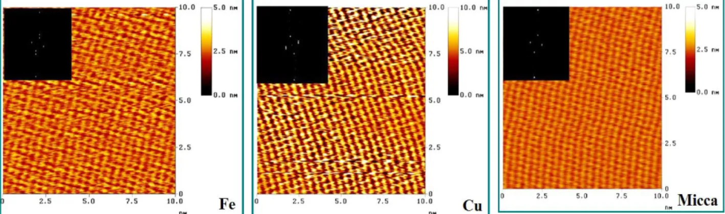
An example for the LB layer characteristic is the follow; the structure of nanolayers prepared from different amphiphiles on three divers solids (iron, copper, mica) are very similar that means the molecules can adhere to all of these solids. The molecules are arranged similarly which is reflected in the nanostructures shown by 2D Fourier transformation (2DFFT) images at high resolution (Fig. 16.4-a,b,c.). This means that the nanostructure of these layers do not depend on the solid surface. Both on the metals and the mica with hexagonal structure 2 pairs of points are
[AUTHOR NAME]Shaban A, Telegdi J, Felhősi I, Molnár-Vörös N 20 observable that are symmetric to the origin. The size of the 2D elemental cells is the follow: α = 0.443±0.05 nm, β = 0.335 ± 0.04 nm, γ = 103 ± 0.5o. The molecules in well-ordered arrangement result in a compact structure with homogeny surface. This allows a strong contact with sensing molecule.
Figure 16.4. Structure of LB layers on different supports; a: nanofilm on iron; b: the same nanofilm of copper; c: nanofilm on mica.
16.4.3. Techniques for layer deposition.
1. Spin-coating: applied at laboratory scale; first is the deposition of small quantity of solution into the center of the solid substrate, then starts the spinning at high speed (1500- 6000 rpm); the advantage is that the layer is homogeneous.
2. Dip-coating: in this case the substrate is immersed into the dip-coating solution, and then comes withdraw of the substrate from the solution and the solvent evaporation. The technique is affected by the fluid viscosity and by the fluid density. Advantage of the method is that it results in a uniform, high quality coating. The disadvantage is that it requires precise control and clean environment. The process could be accelerated by heating and UV, IR irradiation. The preparation of several layers is also possible with subsequent steps.
3. Spray coating: in this case, the coating solution is transferred into an aerosol (pressure- driven, nozzle-based atomizer). The solvent viscosity should be reduced. The droplets driven by the carrier gas settle on the solid surface by gravitation or by electrostatic field.
[AUTHOR NAME]Shaban A, Telegdi J, Felhősi I, Molnár-Vörös N 21 4. Inkjet printing: this is applicable at industrial scale; promising technology for electronic
sensing because of its low cost. In this case thin droplets are deposited onto the solid surface from a print head.
5. Layer-by-layer technology (LbL): is a powerful method for preparation of nanostructured multilayered nanocomposites with controlled structure at molecular level. This method is based on alternative adsorption of molecular layers of opposite charges when a solid surface is dipped into solutions of cationic and anionic electrolytes by turns. The technique is simple; the nanolayers are applicable as biosensors as biological materials could be fixed on the nanolayer surface by electrostatic interactions (Ferreira et al., 2004). The polyaniline films are often applied as chemical sensor (Jang et al., 2007) and biosensor (Borole et al., 2004) because of their chemical stability, facile synthesis and low cost. A water solution/dispersion of polyaniline, prepared by interfacial polymerization, can be used for preparation of LbL-technique-modified electrode for pH sensing (Vieira et al., 2011).
16. 4. 4 Nano-layers/nanoparticles characterizations
The nanolayers/nanofilms with or without nanoparticles could be characterized by several different techniques.
Scanning electron microscopy (SEM)
SEM can visualize the surface of the layer in 3D. The electron beam emitted from the cathode goes through an anodic coil (that accelerate the electrons), after focusing the electron beam with a magnetic coil, a special coil makes enable the scanning of the solid surface via the electron beam. When the electrons meet the surface, a part of the electrons will produce the backscattered electrons, the secondary electrons (these two types of electrons will image the surface morphology), and the X-ray photons that give information about the chemicals composition of the scanned surface. With other word, the SEM deliver information about the patterning, morphology of the solid surface under investigation and, at the same time, the materials that form the nanolayer, will be determined.
[AUTHOR NAME]Shaban A, Telegdi J, Felhősi I, Molnár-Vörös N 22 Transmission electron microscopy (TEM)
TEM works similarly to the SEM, but decisive difference is that the electrons cross the surface under investigation. This is the reason that at this technique the material should be very thin. It informs us about the shape of the particles in the film and the diffraction results determine the composition.
X-ray photoelectron spectroscopy (XPS)
XPS involves the detection of electrons emitted from samples with kinetic energies typically below 2000 KeV. The advantage of this method is its surface sensitivity that arises from the short distances that electrons travel at these energies without undergoing inelastic scattering and energy loss. This method provides information on the depth, enrichment, or layering within the XPS analysis volume. Consequently, this method can be used with multiple approaches to obtain important information about layering or coatings on particle and nanoparticle surfaces. Although XPS does not have spatial resolution to analyze individual nanoparticles (with the possible exception of a few special synchrotron-based systems with a highly focused and bright source of X-rays), it is often possible to analyze collections of particles (in a single layer or, effectively, in powder form) to obtain useful information.
XPS is extremely important tool for determination of the presence, composition, and thickness of coatings on nanoparticles, as well as surface enrichment and depletion at particle surfaces. To the surprise, XPS can sometimes be used to determine particle sizes when conditions are not appropriate for analysis by other methods (Baer and Engelhard, 2009).
Scanning Probe Microscopies (SPM)
Atomic force microscopy (AFM) and scanning tunneling microscopy (STM) are powerful methods that have major advances in nanotechnology. The development of these “sharp” tip based probes has made it possible to inspect surfaces of many types of materials with spatial resolutions approaching 1 nm for electrical properties (STM, that measures the tunneling current) or sample topography (AFM that measures the attractive or repulsive forces between the tip and the surface under investigation). AFM can provide 3-D imaging/visualization of nanoparticles distributed on a flat surface. It can provide qualitative and/or quantitative information about physical properties of nanoparticles including size, morphology, surface texture, and roughness.
During scanning, the instrument measures the change in the forces between the tip and the solid
[AUTHOR NAME]Shaban A, Telegdi J, Felhősi I, Molnár-Vörös N 23 surface. There are several possibilities for scanning: in contact mode the repulsive force, in non- contact mode the attractive force is measured. The measurement will result in the morphological image of the surface. The section analysis of the images allows the determination of the particle size, its distribution as well as the numerical characterization of the surface roughness (Greene et al., 2004).
AFM can follow the impact of the magnification as can be seen in Fig. 16.5. a,b,c., which demonstrates how the Langmuir-Blodgett monomolecular layer looks like on iron surfaces when the resolution increases which allows to see the real nanostructure of the nanolayer.
Figure 16.5-a,b,c. LB nanolayer on polycrystalline iron; the influence of the magnification.
Inductive measurements
The superconductive property of the nanofilms can be determined with magnetization measurement.
Electrical transport measurement
Understanding electrical transport through nanostructures necessitates perfect control of their structure and morphology, which can sometimes be accomplished via self-assembly (SA).
Quantum size effects (QSE) in metallic nanostructures appear to be a strong driving force toward self-assembly. This self-assembly mechanism produces films that are atomically flat over macroscopic distances.
16. 4. 5. Modelling of dimensionally constrained materials systems
Modelling of dimensionally constrained materials systems in which a nano-scale trait of the materials (e.g. grain size, film thickness, interfacial boundary, etc.) fundamentally determines its
[AUTHOR NAME]Shaban A, Telegdi J, Felhősi I, Molnár-Vörös N 24 structure-property relationships. At the preparation of nanolayers with nano-sized particles it is important:
1. the nanoparticle size control
2. the shape of the nanoparticle control (at the thermodynamic stabilization not only the size, but the shape is controlled)
3. crystal structure control (the properties of a particle depends on the crystal structure)
4. orientation control (it is important to control the orientation of large arrays of anisotropic nanoparticles onto the solid surface which is influenced by the number of nuclei which could be limited, moderate and overabundant; at the moderate will be formed the a well-organized, compact structure);
In order to prepare a tailored layer with nanoparticles these characteristics mentioned above will influence and determine the quality of the layer.
16.4.5.1 Nucleation of the particle.
The nucleation is really a precipitation, a condensation. When the solution is supersaturated, then starts the precipitation with nucleation. Two types of nucleation are involved into the precipitation. Homogeneous nucleation does not need any foreign species. At the heterogeneous nucleation an external species is involved into the nucleation. The homogeneous one is more difficult than the other type. The formation of nuclei is very energy-consuming as a new phase/interphase is generated.
16.4.5.2. Influence on the particle size.
This is a very important question, as the thickness of the nanofilm will be determined by the size of the particles. The formation of nuclei could be influenced thermodynamically (which defines the solid-liquid interfacial energy) and kinetically (this is responsible for the nucleation and growth of the particles). The interfacial energy could be altered by charge density of the interface and by the chemical composition.
16.4.5.3. Shape control.
The size, the shape and the structure of the particles could be controlled when the system achieved the thermodynamic stability. At the start of a particle formation, first a spherical precipitation is formed on the solid surface. This is explicable with the minimal surface energy as the spheres have the smallest surface-to-volume ratio, and represents the lowest interfacial
[AUTHOR NAME]Shaban A, Telegdi J, Felhősi I, Molnár-Vörös N 25 tension. At a certain particle size, at the so-called critical size, the further growth depends on the diffusion and the shape will further not be necessarily spherical. The reaction and transport rate, stability, recrystallization will influence the particle growth and shape.
In order to achieve the desired particle size, shape and growth, kinetic factors like pH, concentration of reaction reactants, temperature will be determined in advance. By the chemical bonding theory (Xu and Xue, 2008; Xu et al., 2005) can calculate the normal growth rate and several other factors that influence ideal shape of particles. This theory is determined by the vertical growth rate, by the bond number, bond strength, inter-planar distance, and by area of the selected plane.
16.4.5.4. Orientation control
When the difference between the homogeneous and heterogeneous nucleation phenomenon is clear, we can control the orientation of large arrays during the growth of thin films with nanoparticles from aqueous solution. Multi-angular growth of nanoparticles will eventuate when the number of nuclei is limited in the course of precipitation. Perpendicular orientation of the nanoparticles occurs when the number of nuclei is moderate. Large number of nuclei leads to a horizontal arrangement.
16.4.5.5. Patterning
Nano-pattern means periodic arrangement with feature size below 100 nm. For industrial application a nanofilm with periodic fashion is important. By lithographic top-down technique the patterning is easy. On the other hand, bottom-up methods can produce patterned surface with integrate nano-units. The possible techniques are the self-organization, solution method. The supersaturation in a solution is not uniform at the interface (high are at the edges and small at the center).
In the previous examples were shown the importance of the conditions of nanolayer preparation.
When the chemical rout is carefully designed and controlled, all important characteristics (size, shape, structure, arrangement of units) could not only be pre-defined but will be realized in the end-product nanoparticles with the proper physical and chemical properties of the nanolayer.
[AUTHOR NAME]Shaban A, Telegdi J, Felhősi I, Molnár-Vörös N 26 16.5. Applications of functional thin films and nanostructure based sensors.
Due to increasing demand for sensors in new applications, innovative methods for sensor technologies are pursued where nanotechnology could offer one of the most outstanding influences on the basis of small sensor size, inexpensive, high efficiency, stability, and short sensor response time (Fortin, 2009; Lion, 1969). The utilization of nanostructured materials with modified or functionalized surfaces is anticipated to enhance a greater sensitivity and selectivity as the case in biosensing applications. Recently, the nanostructured material characteristics become the cornerstone of the construction of innovative nanosensors.
Nanoparticles in organic coated thin films generally can convert the physical and chemical quantity either into optical or electrical changes. Some semiconductor nanoparticles synthesized in solution show optochemical sensing ability. They are applied for optical sensing. One example is the CdS nanoparticles, which show photochemical properties when adsorbed onto the surface under illumination (Losada-Morales et al., 2001). For the electrochemical sensing an excellent example is the extensive research on SnO2 particles which were used in a system with multiple components. It was demonstrated that the analytes chemisorb onto the surface of the nanoparticles and the resistance changes (Persaud and Dodd, 1982). Another area of chemiresistors is when the organic polymer matrixes are filled with conductive particles. During sensing the resistance increases due to the vapor-induced swelling of the polymer (Lwergan et al., 1996). In other approximation of the topic there were experiments when in the focus gold nanoparticles were coated by alkyl thiol derivatives. These sensors showed improved reversibility, sensibility and response time (Cai and Zellers, 2002). There are some other parameters like temperature, mass, refractive index that change at the interaction of the sensor and analyte. In these cases, not necessarily nanoparticles are the sensing part, e.g. quartz crystal nanobalance measures the mass change, Pt wire thin film resistor the altered heat, the refractive index, reflectance, emission is followed by interferometer or by fluorescence microscope.
Before going into the details of discussion on sensors we have to emphasize the importance of the nanoparticle shape/structure. The preparation methods and conditions determine the shape of the nanostructured materials. They can exist in nano-spheres, nanobelts, nanorods, nanowires.
The real form of the nanoparticle determines all sensing characteristics.
[AUTHOR NAME]Shaban A, Telegdi J, Felhősi I, Molnár-Vörös N 27 The increasing interest of areas like pollution, hazardous gases has led to development of gas- sensing devices. As in most cases the metal oxides semiconductors (transparent or not transparent) are the main constituent parts in devices, the next part is dedicated mainly to these sensors. These functional oxides that have special chemical and physical properties are applied in a great variety of industries like, biomedical application, chemical sensing, information storage etc. (Chen et al., 2016).
The literature about the ZnO and the SnO2 is vast as both materials respond to a huge number of oxidizing and reducing gases. The thin films used for sensing are deposited by different techniques like sputtering, thermal evaporation, chemical vapor deposition, sol-gel technique, thermal oxidation, pulsed laser deposition etc. Other synthesis conditions results not only in films but belt, wires etc.
The SnO2 nanobelts (produced by thermal evaporation) were successfully used as gas sensors (Comini et al., 2002) for measuring at very low concentrations of CO, NO2 and ethanol. The only problem is, that the sensing goes at elevated temperature (CO, ethanol: 400oC, NO2: 200oC) and when both analytes are present the selectivity decreases.
Semiconductor gas-sensors use generally metal oxides like SnO2, ZnO, TiO2, In2O3 that can very sensitively signal toxic gases, alcohol, food quality etc. (Taurino et al., 2002). At room temperature the ozone sensing ability of the ZnO film was demonstrated (Bender et al., 2002).
The authors reported that the sensor response of the ZnO films decreases with increasing grain size.
In case of solid state sensors, the analyte adsorbs/desorbs onto/from the particle surface and meantime one of the physical properties changes. In most cases the change in the conductivity, resistivity proves the sensing ability.
ZnO nanowires in field-effect transistor were investigated as chemical sensor for detection of NH3 and NO2. The selectivity could be tuned by the back-gate potential. Desorption of the sensed molecule can be enhanced by negative gate voltage. Detailed investigation proved that the NH3 molecules have weaker surface-binding strength on ZnO nanowires as compared to NO2
and the chemisorbed molecules captures electrons.
In order to increase the sensitivity and selectivity for different gas molecules, the ZnO was doped by several catalysts like gold, silver, palladium, platinum, ruthenium, aluminum titanium and
[AUTHOR NAME]Shaban A, Telegdi J, Felhősi I, Molnár-Vörös N 28 vanadium (Know et al., 1998; Aslam et al., 1999; Xu et al., 2000). ZnO doped by Al2O3, TiO2
and V2O5 in different concentration is able to measure the trimethylamine in high selectivity and sensitivity.
The hydrogen (in concentration range 2.000 and 20.000 ppm) with a Pd (Pd/ZnO/p-Si device (undoped ZnO film deposited onto p-type Si and doped by Pd) was successfully measured at room temperature. The key role in the sensing is that the surface conductivity of ZnO and the Pd/ZnO interface increases due to the adsorption and chemical interaction of hydrogen.
Copper-doped ZnO nanomaterials can sense the humidity at room temperature (Misra and Pandey, 2016). This is a significant advantage as the metal oxide sensors work generally at high temperature which makes difficult the elaboration of industrial sensor device. The other disadvantage of the high temperature is that there is a drift in the sensitivity caused by shift in the temperature. The Cu-doped ZnO can not only measure the vapor content at low temperature in a wide concentration range (15-95% RH) but the response time, the recovery time, the hysteresis are also more favorable.
The ZnS nanofilm is very good for sensing other gases than the ZnO (doped or not doped) is applied for. This sensor has optimum responses to different gases at, it means that the ZnS film shows high sensitivity at various temperature. The chemicals, which could be quantitatively characterized by ZnS film at very low concentration, are the follows: NH3, CO2, ethanol, H2S, hydrogen, chlorine, liquid and petroleum gas. Advantage of this sensor is that chlorine could be measured at room temperature. On the other and, when the ZnS is applied as a nanowire, it senses the humidity in the concentration range of 22-97%. We have to remember, that the sensitivity increases with increasing the operation temperature.
The nanostructured mixed vanadium oxide thin films are highly sensitive for ammonia sensing (Huotari et al., 2014) according to conductometrical detection. The vanadium oxide crystal structure plays important role in the sensing ability. The pulse laser deposited vanadium oxide thin film has two phases structure: pure V2O5 and a mixture of V2O5 and V7O16. Both types of nanolayers could detect ammonia at ppb level, and, at the same time, they can sense the NO gas but at two decades’ higher limit. According to other observation, the mixed phase film is more sensitive to ammonia.
[AUTHOR NAME]Shaban A, Telegdi J, Felhősi I, Molnár-Vörös N 29 In the future other, new dopants will be introduced into the sensing device to produce nanoparticles with predefined composition, grain size and shape, which helps in responding to the electric field, illumination and to the analytes.
Special type of the sensors is the porous silicon nanostructure prepared with pre-defined properties (porosity, type and condition of anodization), which is a sensitive thermal sensor. In case the analyte undergoes on morphological or chemical changes due to the altered temperature, this sensor can monitor the alteration (Letant and Sailor, 2000; Nassiopoulou, 2005). On the other hand, the porous silicon (often doped with Pd) is applicable for chemical sensing at room or higher temperature. Its operation is based on the measurement of changes in resistance when the sensor is exposed to the atmosphere of the chemical under investigation. Doped porous polycrystalline silicon films could be fabricated by electroless techniques. The kinetics of the chemical reaction could also be evaluated by application of these sensors. Nanostructure- modified nanopore coated microporous PS sensors are sensitive and selective for reversible chemical changing (Baker and Gole, 2014). These devices are applicable for analyzing different gases.
In other case, the macro-porous silicon was coated, electrochemically functionalized by polypyrrole. This sensor was able to detect linear alcohols (from methanol upto hexanol) via photoluminescence detection (Dian et al., 2013).
Carbon nanotube sensors
Generally, two types of nanotubes: single-walled carbon nanotubes (SWCNTs) and multi-walled carbon nanotubes (MWCNTs) are prepared. A SWCNT can be considered as a one-atom-thick layer of graphite rolled up into a seamless cylinder with a diameter of several nanometers, and length in the order of 1–100 microns. MWCNTs consist of multiple layers of graphite wrapped up together to form a tube shape, sharing the same central axis. Their structures guarantee unique electrical (metallic, semi-conductive), physical, chemical and mechanical properties as well as high thermal stability.
There are certain carbon nanotube properties that are relevant to sensors, like the surface area, size and shape, electrical conductivity, chemical reactivity and optical properties (Stetter and Maclay 2004). Carbon nanotubes (CNTs) have been in the focus in inventions of gas sensors that exploit CNTs' unique geometry, morphology, and material properties.