TR .jJV -pjrv
I . NÁDAV Z S , KAJCSOS GY, KOZMA M, KANYO
BUDAPEST
Г Ш ^ Ш И COINCIDENCE SYSTEMS WITH VERY H1SH TIME RESOLUTION
. : i.
ШиВМЕД Ж д а-У *
и
immmE f o r
F h y s i c s
KFKI-1981-11
?(И7
KFKI-1981-11 .i'i
•ii J.
FAST-SLOW COINCIDENCE SYSTEMS WITH VERY HIGH TIME RESOLUTION
ji .
ji I. Náday, Zs. Kajcsos, Gy. Kozma, M. Kanyö
ij Central Research Institute for Physics
H-1525 Budapest 114, P.O.B.49, Hungary
i
il 1;
\
Paper presented at the X. International Symposium on Nuclear Eleatronice,
\1 Dresden, /В 33/
■.!j
<
i
■j M .! ! i 1 i
if
HU ISSN 0368 5330 ISBN 963 371 788 4
*
'
The measuring of very short times has recently become increasingly important. In this paper we describe our studies on the various parts of a timing system in an attempt to improve its parameters. Our investigations covered the detector system, i.e. the transit time differences of the photo
multipliers, the construction of the divider network, the various types of timing discriminators, the time-to-pulse height converters and the gating system. We introduce two types of constant fraction discriminators: one for general timing applications, the other placed inside the detector head for positron lifetime measurements.
АННОТАЦИЯ
Измерение очень коротких времен в последнее время приобретает все боль
шее значение. В статье описываются работы, проведенные для улучшения пара
метров систем хронирования. Исследования были расширены на детекторы /т.е.
на изучение разностей времен пролета электронов в ФЭУ/, конструкцию делитель
ной цепи напряжения, разные типы дискриминаторов хронирования, а также и на время-амплитудные преобразователи и систему стробирования. Разработаны два типа дискриминаторов "constant fraction", один из которых служит для решения общих задач хронирования, а другой, непосредственно встроенный в головку де
тектора, для измерения времен жизни позитронов.
KIVONAT
Az igen rövid idők mérése mostanában egyre nagyobb jelentőségre tesz szert. Ebben a cikkben egy időzítő rendszer paramétereinek megjavítása cél
jából végzett munkánkat Írjuk le, Vizsgálataink kiterjedtek a detektorokra Iazaz a fotoelektronsokszorozókban fellépő futási idő különbségek tanulmá
nyozására/, a feszültségosztólánc konstrukciójára, a különböző tipusu idő
zítő diszkriminátorokra valamint az idő-amplitudő konverterekre és a kapuzó rendszerre is. Kidolgoztuk a "constant fraction" diszkriminátorok két típu
sát, egyet általános időzítő feladatok ellátására, egy másikat pedig köz
vetlenül a detektor-fejbe építve pozitron élettartam mérések végzésére.
I
portant in nuclear physics experiments, in time-of-flight measurements, in perturbed angular correlation measurements, in the determination of the life
time of excited molecular and atomic levels in organic radiation chemistry, and in positron lifetime measurements. As the boundaries of the field of po
sitron annihilation studies are extended, a higher priority is given to the study of metals and their alloys. Such studies require very accurate lifetime measurements. These lifetimes being very short, the need for improvement of
the self-resolution of fast-slow coincidence systems is of great importance.
In this paper we describe our studies on the various parts of a timing sys
tem in an attempt to improve its parameters. Our investigations covered the detector system, i.e. the transit time differences of the photomultipliers, the construction of the divider network, the various types of timing discrimi
nators, the time-to-pulse height converters and the gating system. We intro^
duce two types of constant fraction disciminators: one for general timing applications,the other placed inside the detector head for positron lifetime measurements.
Our basic measurement setup was the well known fastrslow gamma-gamma timing coincidence system. The block diagram can be seen in Fig. 1.
The resulting FWHM value of the time resolution íb considerably influ
enced by the properties of the detector systems, i.e. the scintillators and the photomultipliers.
A wide range of plastic scintillators exists such as KL 236, Pilot B, Naton-136, NE 102, NE 111, NE 213, etc, each having different timing capa
bilities. Their performance has been extensively tested [1]. From the com
parison of several types it has been found that the best time resolution is obtainable with the NE 111 scintillator. In our experiments we used this type of scintillator with the dimensions 0 25 x 25 mm. The shape and the surface of the scintillator also influence the time resolution of the system [2] and these factors are under investigation in our laboratory.
Several sources of time-spread of the timing signal originate in the photomultiplier itself. Resolution capabilites are limited by the random de
viations of transit times across the multiplier [3,4,5]. The main causes of
time-spread are: spread in emission time of the secondary electrons, spread in emission velocities of the secondary electrons, space-charge effects and spread in electron path, length.
Fig.l Fast-elow coincidence measurement setup
The path length depends on the angle of emission and on the site of emission of electrons from the photocathode. Because the scintillation photons are distrib
uted over a region of the photocathode, determined by the size of the scin
tillator, this effect directly influences the time resolution of the timing system. This systematic transit time variation was measured on a few
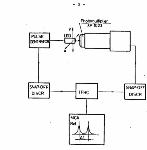
XP 1023 PM tubes in the configuration shown in Fig. 2.
V
*
Fig. 2 Transit time shift measuring setup
The light source was a fast rise-time GaAs light emitting diode
/Monsanto MV 55/ mounted directly on the pins of a mercury-wetted relay. A capacitor was periodically discharged through the LED giving a light pulse of about 1 nsec rise-time and 20 nsec width. The diode worked in the forward direction. In spite of the lower sensitivity of the photocathode in the
region of 6600 8 /the wavelength of the light emitted by the LED/, the output pulse on the anode of the PM was about 5V on 50 Ohms at an operating high voltage of 2.4 kV; the time resolution of the system was 90 psec. The focused light beam of the LED was directed perpendicularly to the window surface of the multiplier. The diode assembly was movable in both the X and the У direc
tions with a high degree of accuracy. The results of the measurements can be seen in Fig. 3 to Fig. 5.
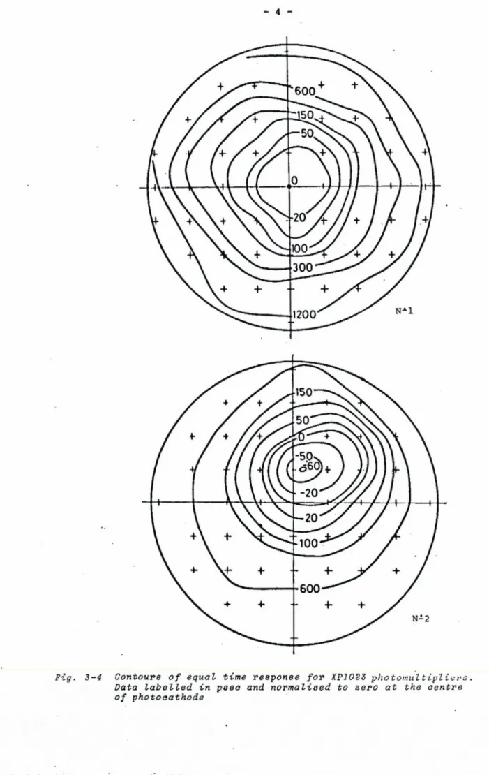
With the adjustment of the voltage on the first focusing electrode of the PM tube the optimal transit time difference can be obtained with the scintillator mounted in the centre of the photocathode. It should be noted, however, that in some cases the best transit time differences could be
achieved if the scintillator were shifted from the centre of the photocathode.
Fig. 3-4 Contours of equal time response for XP1023 photomultipliers . Data labelled in psea and normalised to zero at the centre of photocathode
H P 1023
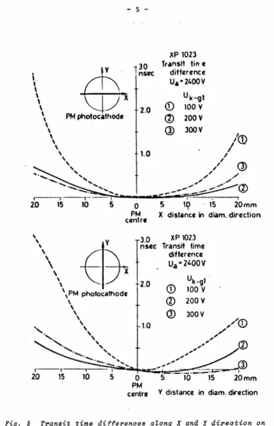
Fig, S Transit time differences along X and X direction on the photocatode in function of the voltage on the first focusing electrode /V
The types of fast multipliers extensively used for timing applications are: XP 1020, XP 1021, XP 1023, XP 2020, RCA 8575, RCA 8850, RCA 31024. In general, the fewer the stages in the multiplier, the higher the time resolu
tion that can be obtained, but since the output pulse amplitude is propor
tional to the number of stages, the processing of the timing signal is more difficult. In our experiments the 12-stage XP 1023 photomultipliers were used because their quartz-window enabled a higher sensitivity in the ultra
violet region.
In the detectors a modified version, of the factory-recommended B' type voltage divider was used [6]. The current of the divider is 3 mA at 2.5 kV.
With this current the detector can be used up to 80 kHz integral rate/ 22Na/.
The voltages on the electrodes of the PM tube corresponded to the B' type divider but a part of the divider chain was separated into two paths. This solution enabled a very compact arrangement to be obtained: the whole divider and the decouple capacitors could be mounted directly on the socket of the multiplier. By avoiding long wires the rise-time of the anode pulse was 1.7 nsec; ringing and oscillations were eliminated when the anode was ter
minated in 50 Ohms.
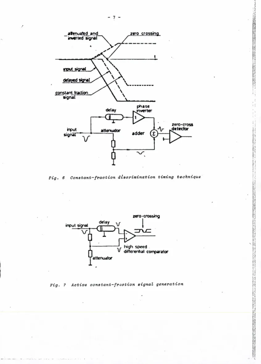
The other fundamental part of a high resolution timing system is the timing discriminator. The types which are used at present are: leading-edge /LE/ discriminators, snap-off /SN/ discriminators, and constant-fraction /CF/ discriminators. The disadvantage of LE discriminators is well known, this type causes a systematic time walk depending on the ratio of the input pulse amplitude and the discrimination level. This walk is theoretically eliminated by using the constant-fraction timing technique /Fig. 6/. It can be seen that the time of zero crossing is independent of the amplitude of the input signal. Because of practical considerations the delay of the input signal is about 0.5 t^ /where t^ is the rise-time of the input signal/ and the fraction is about 0.2. The zero-crossing detection in constant-fraction discriminators can be realized by tunnel diodes or by high speed integrated comparators. The use of tunnel diodes could give better results but because of the more sophisticated circuitry and the thermal and long term instabil
ities of these devices the use of IC comparators is more advantageous [8-10).
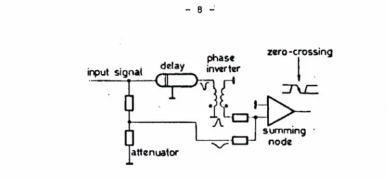
There are two ways to produce the constant-fraction signal: active /comparison/ and passive modes. With the active mode /shown in Fig. ?! the input signal is split into two parts, one is attenuated, the other delayed;
the subtraction takes place at the first differencial stage of the integrated comparator since the delayed signal is fed into the inverting input, while the attenuated signal into the noninverting one. With the passive mode /also shown in Fig. 8/ the two signals are added at the same node of the zero- -crossing detector, but in this case a high speed phase inverter has to be used which can be realized by a high speed pulse transformer or by a shorted delay line.
/
I
Fig. ff Constant-fraction discrimination timing technique
Fig. ? Active constant-fraction signal generation
■
Fig. 8 Passive constant-fraction signal generation
In the latter case the phase inverting shorted cable can serve as a delay element. Our investigation shows that the passive generation of the constant fraction signal gives a better time walk because of the intrinsic linearity of the circuit. The zero-crossing detector can be realized by ECL line receivers.
In general, commercially produced start-stop time-to-amplitude converters /ТАС/ can give good results but in high rate measurements they cause signifi
cant dead time losses. If the ambient temperature of the measuring system is not stabilized the temperature dependence of these converters causes consider
able shifts of the coincidence curve. By the use of purpose designed delayed- -start type TAC, these disadvantages can be eliminated [11].
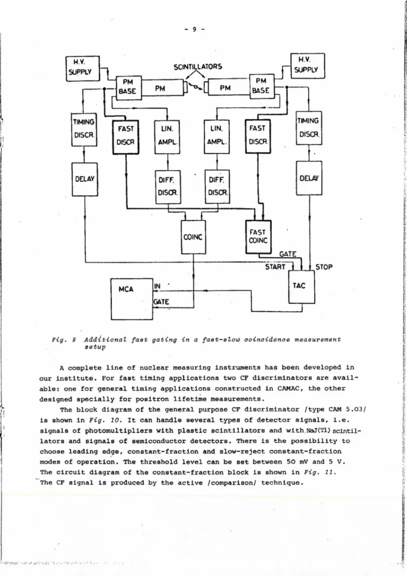
In a fast-slow coincidence system the energy side channels are composed of shaping amplifiers, single channel analysers and a coincidence unit /Fig.l/.
This conventional setup has some drawbacks: the TAC must handle all single events exceeding the threshold of the timing discriminators and because of pile-up effects in the slow energy selecting side "incomplete gating" can occur. These problems can be eliminated by using additional fast gating [12]
/Fig. 9/. Since the thresholds of the fast discriminators are below the lower level of the window set on the SCAs, the instabilities of the threshold of the fast discriminators hardly influence the stability of the gating system.
Using this double gating system better time resolution and a clearer coinci
dence curve can be obtained.
The use of high stability differential timing discriminators enables the slow, energy selecting side channels to be avoided [13]. In this case the TAC is gated so that it must start the processing only if a coincidence has occurred. Pile-up is eliminated due to the fast gating. This system gives better time resolution and improved count-rate capability, while at the same time using simpler electronics.
H V.
SUPPLY
TIMING DISCR
DELAY
SCINTILLATORS
AMPL. AMPL.
DIFF.
-
DIFF.
DISCR. DISCR.
PM
BASE PM
S >■
PM
PM BASE
i
FAST LIN. LIN. FAST
DISCR.
H.V.
SUPPLY
TIMING DISCR.
DELAY
STOP
Fig. 9 Additional fast gating in a faet-elow ooinoidenae measurement setup
A complete line of nuclear measuring instruments has been developed in our institute. For fast timing applications two CF discriminators are avail
able: one for general timing applications constructed in CAMAC, the other designed specially for positron lifetime measurements.
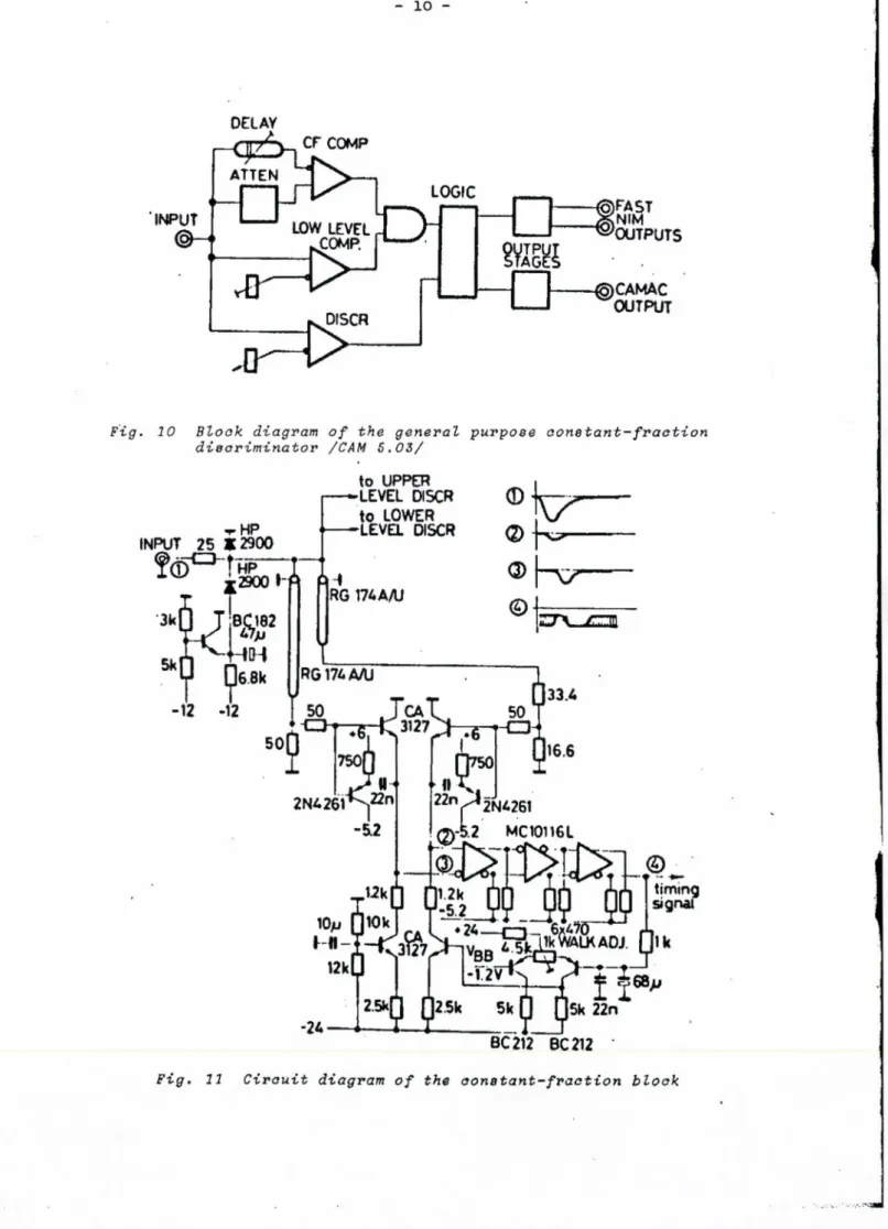
The block diagram of the general purpose CF discriminator /type CAM 5.03/
is shown in Fig. 10. It can handle several types of detector signals, i.e.
signals of photomultipliers with plastic scintillators and with.NaJ(Tl) scintil
lators and signals of semiconductor detectors. There is the possibility to choose leading edge, constant-fraction and slow-reject constant-fraction modes of operation. The threshold level can be set between 50 mV and 5 V.
The circuit diagram of the constant-fraction block is shown in Fig. 11.
The CF signal is produced by the active /comparison/ technique.
DELAY
Fig. 10 Block diagram of the general purpose constant-fraction discriminator /CAM 5.03/
Fig. 11 Circuit diagram of the constant-fraction block
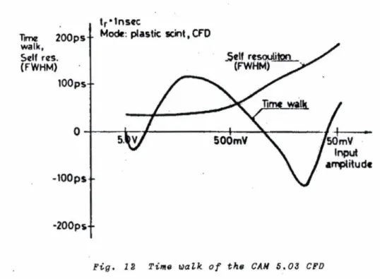
The fraction is 30% and the delay is 1.3 nsec for plastic scintillators, 2.0 nsec for NaJ (Tl) scintillators and 15 nsec for semiconductor detectors. The measured time walk and self-resolution is shown in Fig. 12 [14).
Fig. 12 Time walk of the CAM 5.03 CFD
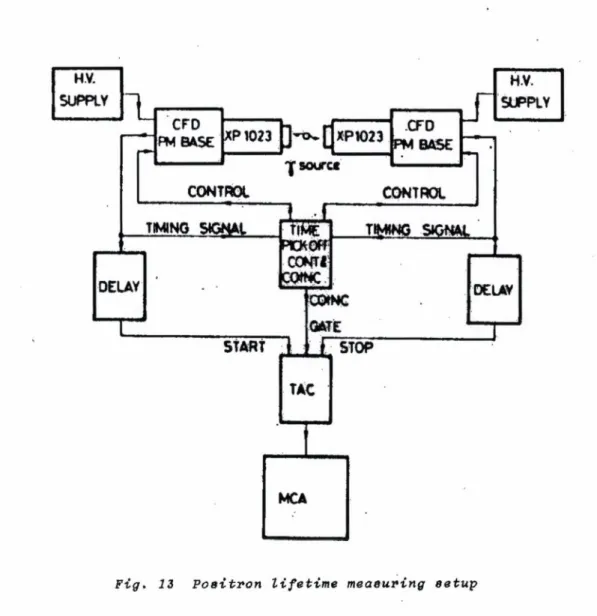
The CF discriminators for positron lifetime measurements are placed inside the detector heads. The discrimination levels and the window widths of the two timing discriminators can be controlled from a dual time-pick-off control module. This module serves as a fast coincidence unit as well. The positron lifetime measuring setup uelng these instruments is shown in Fig.
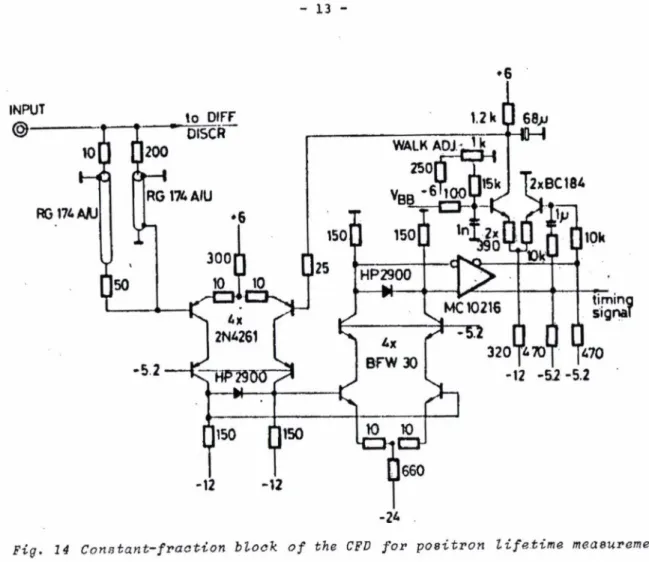
13. The CF block of the CF discriminator can be seen in Fig. 14. In this case the constant-fraction signal is produced by the passive technique be
cause the low walk value for large signals was of great importance. To ensure the proper timing capabilities even at high input rates a unique feedback is used in the zero-crossing detector circuit to stabilize the quiescent voltage at its output. Because the CF discrimination ie inside the PM base, the length of the cable between the anode of the PM tube and the input of the discriminator is very short, this means that matching problems do not arise. The discrimination levels can be set in the range 0.1 to 5.1 V, the window width range is 0.05 to 2.5 V. The resolution of the coincidence cir
cuit is adjustable between 50 nsec and 250 nsec. The time walk is less than + 80 psec in a dynamic range of 50:1, measured with an input signal rise time of 2 nsec.
As a result of our investigations and the development of our new timing moduls, the resolution of our positron lifetime measuring system has im
proved to 260 рзес with the general purpose CF discriminator and to 220 psec
with the special CF discriminators using X P ’1023 PM and 0 25 x 25 mm NE 111
%—® gg
scintillators and 20% energy window. Fig. 15 shows the prompt curve for Co with 20% energy window.
Fig. 13 Poaitron lifetime measuring setup
г
*6
Fig. 14 Constant-fraction block of the CFD for poeitron lifetime measuremente
Ю 3Н Counts
ю 2 -1
ю ’ H
10
/ f w h m*^ i H260psec \
13.2psec/ch XP1023 2.4 kV
NE111 *25x25 mm 20V. Co“
CFO CAM 5.03 4---\---4- -F-
’ F W H M \
A
TTzop e « - .
*
9
9
225 240 255 270 285
* 13.2 psec/ch ХР102Э 2.4 kV NET 111 *25» 25 mm 20 V. Co“
CFD: spec
--^--- 1--- 1— Channel number
— I----1--- 300 315 330 345 360
Channel number Fig. 15 Coincidence curves of the measuring Systeme
REFERENCES
[1] Suvra Sanyal, S.C. Pancholi, S.L. Gupte
Subnanosecond Timing Studiee With "tlastic Scintillation Detectors.
Nucl.Instr. and Methods 136/1976/ 157-163 [2] G. Kögel
A Fast Positron Lifetime System with Large Scintillators.
Proc. 5th Int. Conf. Positron Annihilation /1979/9B-IV-7
[3] Photomultipliers - Space Charge Effects and Transit Time Spread.
EMI Document 1977 [4] A.R. Wilson
Variations in Transit Response Across a Small Plastic Scintillation Detector. Nucl. Instr. and Methods 130/1975/ 597-598
[5] B. Leskovar, C.C. Lo
Single Photoelectron Time Spread Measurements of Fast Multipliers.
Nucl. Instr. and Methods 123/1975/ 145-160
[6] Philips Technical Literature: Photomultipliers 1970 17] M.R. Maier, P. Sperr
On the Construction of a Fast Constant Fraction Trigger with Integrated Circuits and Application to Various Photomultiplier Tubes.
Nucl. Instr. and Methods 87/1970/ 13-18 (8] T.M. Hall
Lifetime System with Stabilised Timing Discriminators Nucl. Instr. and Methods 117/1974/ 253-259
[9] R. Myllylä, M. Karras
Positron Lifetime Spctrometer for Metal Studies Applied Phisics 4, 157-159 /1974/
(10] J. Pouthas, M. Engrand
A Timing Discriminator for Channel Plate Electron Multipliers Nucl. Instr. and Methods 161/1979/ 331-337
(111 S. Nano, K. Yamaguchi, H. Ino, S. Nishikawa
A Simple and Fast Time-Analysis System for Positron Annihilation Proc.5th Int. Conf. Positron Annihilation /1979/9B-IV-8
[12] Zs. Kajcsos, J.Ch. Abbe, J.P. Oberlin, G. Sereny, A. Hassler Optimization Attempts for Time Resolution in Fas-Slow Coincidence Systems. Centre de Recherches Nucléaires et Univerité Louis Pasteur, Strausbourg CRN/CNPA 75-2 5
[13] M.O. Bedwell, T.J. Paulus
A New High Rate Positron Lifetime Measurement System Proc. 5th Int. Conf. Positron Annihilation /1979/9B-IV-6 [14] M. Kanyó
Thesis. Technical University Budapest, 1979 /unpublished/
Kiadja a Központi Fizikai Kutató Intézet FelelSs kiadó: SzegS Károly
Szakmai lektor: Zarándy Aladár Nyelvi lektor: Zarándy Aladár Gépelte: Beron Péterné
Példányszám: 475 Törzsszám: 81-95 Készült a KFKI sokszorosító üzemében FelelSs vezetS: Nagy Károly
Budapest, 1981. február hó