GENERALIZED TWO-IMPULSE SCHEME FOR REORIENTING A SPIN STABILIZED VEHICLE
Carl Grubin^"
Nortronics, Northrop Corp., Palos Verdes Estates, Calif.
ABSTRACT
The dynamics of a generalized two-impulse scheme for reori- enting the attitude of a symmetric, spin stabilized vehicle are analyzed. The term generalized derives from the fact that the precession angle is not limited to 180°. If all system parameters are nominal and the torques are ideally impulsive, then the scheme is theoretically perfect. Mechanization of this scheme by means of body fixed rockets is considered, and the effect of non-ideal conditions on system accuracy is ex- amined. These conditions include non-nominal values of spin speed, transverse moment of inertia and a finite time of rock- et firing.
INTRODUCTION
Recent literature on the problem of spin axis reorientation includes papers by Windeknecht (1)^ and Cole, Ekstrand and O'Neill (2). Ref. 1 proposes achieving the desired attitude change by a succession of 180° precessional motions each re- sulting in a small attitude change (small angle approximations assumed valid) until the spin axis arrives at an attitude cor- responding to the dead zone of the sun sensors. Ref. (2) prescribes the desired attitude change and solves for the nec- essary torques but gives no details on mechanization. Other recent papers which propose active attitude control systems for spin stabilized vehicles have been published by Adams (3), Freed (4), and Grasshoff (5) but none of these explicitly dis- cusses the reorientation problem.
The present paper describes an open loop, two-impulse Presented at ARS Guidance, Control, and Navigation Conference, Stanford, Calif., Aug. 7-9, 1961.
^-Research Scientist, Electronic Systems and Equipment.
^Numbers in parentheses indicate references at end of paper.
torquing scheme for reorienting the spin axis through finite angles using a single precessional motion. There is no re- striction either to small attitude changes or 180° of preces- sion. The first torque initiates the maneuver, the second terminates it. The two torques have definite magnitudes and directions which are functions of the vehicle moments of in- ertia, spin speed, and in general the attitude change, and are separated by a definite time. The initial torque serves to establish the total angular momentum vector^ such that the spin axis precesses in the direction of the desired attitude.
When the desired attitude is achieved, the concluding impulse aligns the total momentum with the spin axis and the maneuver is completed. For given inertias, spin rate, and attitude change, the equations still permit a degree of freedom in the choice of the precession angle, or the conical angle between the spin and total momentum vectors. A precession angle of 180° minimizes the required torque impulse but maximizes the maneuver time. Smaller precession angles reverse these ef-
fects. The implications of both possibilities are examined.
This paper is in three parts: In the first part the funda- mental dynamics of the scheme are explained, and in the second the problem of locating the torquing rockets on the spinning body is examined. The last part of the paper considers the problem of system accuracy in the presence of deviations from nominal; in particular, the effects of variations in spin speed, transverse moment of inertia, and finite torquing time are examined.
FUNDAMENTAL DYNAMICS
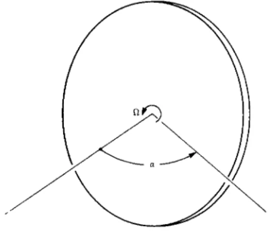
Fig. 1 shows the schematic of the spinning, symmetric ve- hicle. It is assumed that initially the vehicle has only the constant spin rate Ω about its symmetry axis. The problem is to change the spin axis attitude by the angle a , where the di- rection of a with respect to inertial space is known. This must be so for any given application.
Fig. 2 shows the precession geometry. Axes XYZ are inertial and so chosen that at t = 0 , the vehicle spin axis, located by unit vector , lies in the XZ plane at angle θ to the Ζ axis.
An initial impulsive torque of magnitude
J. = Hg tan θ [1]
^Henceforth, unless otherwise noted, momentum is synonymous with angular momentum.
where Hg = spin momentum, 0Ω C = spin moment of inertia Ω = spin speed
is applied at t = 0 in the XZ plane perpendicular to^the spin axis, such that at t = 0+ the total momentum vector Η is es- tablished along the Ζ axis. This momentum vector remains con- stant, since no further torques are applied for the time being.
The spin axis then precesses around at a definite rate which will be given later. At the appropriate time when ζ has turned through α relative to its initial position, the final impulsive torque Jf, whose magnitude is also given by Eq. 1, is applied as shown in Fig. 2. This brings the Η vector into coincidence with the spin axis, which then remains stabilized in space in its desired attitude. The maneuver is completed.
The geometrical relations that obtain here are those between α, Θ, -φ, and 7 , where α is the attitude change, Q is the half- apex angle of the precession cone, if is the precession angle, and 7 is the angle between the impulse vectors J^, Jf and the cx plane, defined as the plane formed by the initial and final positions of the spin axis, ζ-^ and ζ £ , respectively.
The components of any vector A are designated as
A = (Αχ, Αγ, Az) [2]
so that from Fig. 2
ζ . = (sin Θ , 0, cos
Q)
J" [3]
= (sin
Θ
cosψ,
sinθ
sinψ
9 cosQ)
Thus
· = cos oc = sin
Θ
cosψ +
cosQ
which can be reduced to
θ sin (a/2) r ,
Si n sin (ψ/2) L J
Given a , there is a degree of freedom in the choice of -φ or Q.
For il - 180°, Eq. 4 reduces to θ = α/ 2 , and the precession axis and the initial and final attitudes of the spin axis are all coplanar. For those applications in which α is not def- initely known initially, but is an inflight variable, this degree of freedom can be used to make θ - Constant Ξ Qç for all a , where necessarily by Eq. 4, the α range would be
limited to 0 < α < 29ç. The advantage of this is that the torque impulse given by Eq. 1 becomes
and thus is constant for all a. Otherwise, the impulse magni- tude is α-dependent, which could present mechanization
difficulties.
By employing a technique similar to Eq. 3, it is found that for 7
where Θ is given by Eq. 4. Again, for the 180 precession θ = α/2, yielding 7= 0 , so that the impulses lie in the α plane.
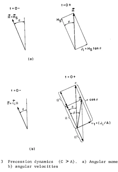
The dynamical state of affairs are now examined. This is best understood with the aid of Figs. 3 and 4, which show the diagrams of angular momenta and angular velocities. Here one must distinguish between the cases C > A and C < A, where C, A are the spin and transverse moments of inertia.
The case C > A is first considered. Referring to Fig. 3, the diagrams labeled t = 0- show the total angular momentum and velocity prior to impulse application. The angle Θ be- tween these vectors and the vertical line has no physical meaning initially. Afterward the vertical line becomes both
the direction of the (constant) total momentum and the preces- sion axis. This is shown in the t = 0+ figures. At t = 0 an impulsive torque Hg tan Θ Ξ is applied at right angles to the spin vector and in the XZ plane of Fig. 2. This jumps the total momentum vector to the vertical line as noted in the foregoing.
Reference is now made to the diagram of angular velocities at t = 0+. One sees first the jump in transverse angular ve-
locity in amount (J^/A) Ξ COT. This combines with the original spin velocity to make the resultant angular velocity CO. Now 00 can be resolved into the oblique components \i along the Η di- rection and Ω ' along the spin axis. One concludes then that Μ must be the precession velocity and Ω1 the new spin velocity.
Thus, for C > A, there is a jump in both the magnitude and di- rection of the spin velocity.^ It is shown in (6) that Ω ' and
4-It is noted that a rate gyro whose sensitive axis is along the spin axis would still measure Ω .
J. = Hs tan 9C
cos 7 = cot θ tan (a/2) (0 < 7 < π/2)
μ are related by the equation of free precession
Ω' = ( C ~ A ) μ cos θ (C > A) [7]
The other relations of interest are those for μ , the preces- sion velocity, and T, the precession time. These are
μ = ω /sin Θ = (H/A) sec Θ
3 [8]
Τ = ( f / μ ) = (A/Hs) -ψ cos θ
so that Ω1 = (C " A^ Ω (C > A)
The angle β in Fig. 3(b) is obviously also available but is of secondary interest. For the case C < A, Fig. 4, the dif- ference is that the spin velocity is reduced from Ω to Ω' but does not reverse direction. The relation between Ω and Π' is still given by Eq. 8 upon replacing (C - A) with ( A - C ) .
The angular velocities and momenta of Figs. 3 and 4 preserve their relative orientation as they precess around H. When time Τ given by Eq. 8 has elapsed, an impulse of magnitude Jf_^= J-j_ is applied perpendicular to the spin axis and in the Ζ Cf plane of Fig. 2 so as to null the transverse momentum.
All the dynamical changes that occured from t = 0- to t = 0+
are reversed; in particular the spin velocity jumps from Ω' back to Ω. Thus the desired attitude change is accomplished.
At this point a few simple calculations may be enlightening.
In particular, the torque and maneuver time ratios are com- pared as a function of α for the θ = 9ç and the 180 preces- sion cases. Eq. 5 gives the impulsive torque for the 0q case, whereas for the 180° precession, Ji = Hg tan (a/2).
Thus
Aj Ξ ( j £c/ J1 8 0) = tan 9c/tan (a/2) [9]
For the maneuver time, using Eq. 8
T0 = (A/Hs) f ( 0C) cos Qc [10a]
c
where from Eq. 4
"sin (a/2)"
sin ec ir (θο) = 2 sin
Also
T
1 8 0
= 7 1 ( A /V
C O S ( < X / 2 )^
1 0 b]
T h u s
λχ Ξ ( Τθ / T18) = -φ (Ö0 c) c o s θα/ τ τ c o s (α/2) [ll]
E q s . 9 a n d 11 a r e p l o t t e d i n F i g . 5. I t i s s e e n t h a t A j > 1 a n d λχ < 1 a l w a y s . F o r e x a m p l e , if t h e d e s i r e d α w e r e 90 , t h e n b y c h o o s i n g 6q = 60 t h e i m p u l s e r e q u i r e m e n t w o u l d b e a b o u t 757o g r e a t e r t h a n w i t h t h e 180 p r e c e s s i o n c a s e . C o n - v e r s e l y , t h e m a n e u v e r t i m e w o u l d b e o n l y a b o u t 4570 o f t h e 180
m a n e u v e r t i m e . F o r a g i v e n Gq> t h e l a r g e s t v a l u e o f α w h i c h c a n b e a c h i e v e d i s α = 2Qq, a t w h i c h p o i n t t h e 0q s c h e m e a l s o i m p l i e s a 180 p r e c e s s i o n . F o r α = 180° t h e t w o c a s e s a r e a l s o c o i n c i d e n t ; b o t h r e q u i r e a n i n f i n i t e i m p u l s e a n d h a v e a z e r o m a n e u v e r t i m e , w h i c h c l e a r l y i m p l i e s t h a t t h e t w o - i m p u l s e s c h e m e b e c o m e s i m p r a c t i c a l f o r α c l o s e t o 180°.
T O R Q U E M E C H A N I Z A T I O N U S I N G B O D Y F I X E D R O C K E T S
T h e p r o b l e m n o w i s t o d e t e r m i n e t h e a p p r o p r i a t e b o d y a x e s a l o n g w h i c h t o a p p l y t h e i m p u l s i v e t o r q u e v e c t o r s a n d Jf s h o w n i n F i g . 2. I t h a s a l r e a d y b e e n s e e n t h a t t h e s e v e c t o r s m a k e a n g l e 7 w i t h t h e α p l a n e , t h e p l a n e o f a n d ζ^.
I n F i g . 6, X Y Z a r e i n e r t i a l a x e s c h o s e n t o b e c o i n c i d e n t w i t h b o d y a x e s x y z at t = 0 . A x i s z i s a l w a y s t h e s p i n a x i s ,
t h e X Z p l a n e is c o i n c i d e n t w i t h t h e α p l a n e , a n d X i s c h o s e n s u c h t h a t α is d i r e c t e d t o w a r d X . A x e s Y a n d y c o m p l e t e t h e i n e r t i a l a n d b o d y s y s t e m s i n t h e u s u a l r i g h t - h a n d s e n s e . (It i s n o t e d t h a t t h e X Y Z s y s t e m s o f F i g s . 2 a n d 6 a r e d i f f e r e n t . ) N o w , f o l l o w i n g f r o m F i g . 2, t h e t o r q u e i m p u l s e m u s t b e a p - p l i e d a s s h o w n i n F i g . 6, w h e r e
J. = H t a n θ
1 8 [12]
c o s Ί± = c o t θ t a n (a/2)
a n d t h e r e l a t i o n a m o n g α, Θ, a n d ψ i s g i v e n b y E q . 4. T h e t o - t a l m o m e n t u m v e c t o r Η i s t h u s e s t a b l i s h e d a s s h o w n in F i g, ^ 6 ,
a n d a x i s z p r e c e s s e s a r o u n d Η t o i t s f i n a l p o s i t i o n a l o n g Cf.
T h e q u e s t i o n n o w i s : W h e r e i s t h e f i n a l i m p u l s e Jf l o c a t e d w i t h r e s p e c t t o t h e b o d y ? A l l t h a t i s k n o w n i n i t i a l l y is t h a t Jf m u s t b e p e r p e n d i c u l a r t o t h e s p i n a x i s ; h e n c e t h e i n i t i a l p o s i t i o n o f 7 f c a n b e l o c a t e d b y t h e s i n g l e a n g l e 7f a s s h o w n in F i g . 6. T h e f i n a l p o s i t i o n o f Jj ( E 7 f> T) w i t h r e s p e c t t o
the inertial system can be determined by noting that since 13 is a constant during the precession, and the spin momentum vector at the conclusion of the precession lies along ζ^, then
H
s
^f + ("^f,τ
} = ^ = ( Ji co sV
Ji si nV V ^
where the minus sign is used so that application of + Jf ^ will null the transverse momentum at the conclusion of the maneuver. Using Eq. 12 in Eq. 13 and the trigonometric
identities
(1 + cos a ) tan (a/2) = sin a (1 - cos a ) = sin a tan (a/2) the direction cosines
as
(cos α cos 7^,
Eq. 15 gives the desired final position of Jf with respect to the inertial system of Fig. 6. The problem now is to locate Jf in its initial position with respect to XYZ; for when this is done, 7f will be determined, since the body and inertial axes are coincident at t = 0. The concept of finite rotations proves very useful for solution of this problem, in the fol-
lowing way. At the conclusion of the maneuver the final at- titude of any line in the body, starting from its initial at- titude, can be arrived at by two rotations, in the order listed:
1) Rotation around the precession axis, Η in Fig. 6, through the precession angle i1 given by Eq. 4; and
2) Rotation around the final spin axis attitude [which itself has been rotated according to 1)] through the spin angle φ Ξ Ω' Τ [where Ω'5 Τ are given by Eq. 8] using the final at- titude under 1) as the initial attitude.
Thus the problem reduces to determining the initial attitude of Jf such that after the body undergoes the rotations de- scribed in 1) and 2), the final attitude is given by Eq. 15.
An expression for finite rotation applied in reverse is re- quired. Designating
"rf = unit vector along the final attitude
~r0 = unit vector along the initial attitude
"e = unit vector along the rotation axis
Φ = angle of rotation, measured positive around "e in the sense of the right-hand convention
of a unit vector along Jf χ are found
- sin 7^, - sin α cos 7.) [l5]
then it is shown in (7) that^
"?o = cos Φ + "e(l - cos Φ) (r^ · "e) 4- (r^ x "e) sin Φ [ΐβ]
Eq. 16 determines the initial attitude ~rQ such that when ~r0 is rotated around axis ~e through angle Φ, the prescribed attitude
"rf is obtained. Eq. 16 is then applied twice in the order 2 ) , 1) , using appropriate axes and angles, to locate Jf initially with respect to XYZ and hence determine 7f.
EFFECTS OF NON-NOMINAL PARAMETERS AND FINITE TORQUING TIME It is clear from the foregoing analysis that mechanization of the two-impulse scheme requires a priori knowledge of the vehicle spin speed Ω and the moments of inertia C and A. Fur- ther, once the rockets have been located on the body, torquing cannot be initiated until the rockets have spun into their correct direction with respect to the a plane.
In setting up tolerances for mechanizing this scheme there are several potential error sources that could be investigated.
These include non-nominal spin speed and moments of inertia, non-nominal values of torque and/or torque misalignments, and non-nominal delay time between the initial and final torques.
Any of these could be significant since the maneuver is open loop. The error investigation has been limited to the effects of non-nominal spin speed, transverse moment of inertia, and finite torquing time. Manifestly, it is desirable to obtain some estimate of the effect of the last on system accuracy.
For investigating the effects of errors in Ω and A, the viewpoint is that some definite value of α has been called for
(in conjunction with a nominal Θ), and that the torque impulse magnitudes, location with respect to the vehicle, and the de-
lay time between them are all nominal. But there is a small perturbation in Ω or A, expressible as a fraction of the nom- inal value. Since the torques are still assumed impulsive, then the finite rotation concept can be used again. In this case it is used in the forward version where (see Eq. 16) rQ, e, and Φ are now given and one desires to find rf. The for- ward version of Eq. 16 is
r = r cos Φ + e(l - cos φ) (r · "e) + (e χ r ) sin φ [17]
^Or see (8), where scalar expressions for finite rotation are given.
To determine the effect of an error, Eq. 1 7 is applied three times. First, use is made of the existing total momentum vec- tor as the equivalent axis, with the true precession angle (determined by the existing precession rate and nominal delay time) as the equivalent angle, to locate the spin axis immedi- ately prior to application of the final impulse Jf. Then the direction along which Jf is applied is found by two further applications of Eq. 1 7 as described under 1 ) and 2 ) in the previous section. Under 2 ) the true spin angle (determined by the existing jumped spin rate Ω ' and nominal delay time) must be used. When Jf is applied along this direction it combines with the previous momentum to form the final momentum Ηχ, which now remains fixed in space. Since the spin axis is, in general, now not coincident with , then the spin axis will precess indefinitely around Ηχ in the absence of subsequent external torques. Two angles then describe the accuracy of the maneuver:
1 ) Angle ô between Ηχ and the desired spin axis attitude.
Since the direction of "ST is the average attitude of the spin axis, then δ is the average error.
2 ) The half-apex angle Of between Ηχ and the spin axis.
Thus the maximum and minimum values of the angular error are ( ô + Of) and I δ - Gf \ , respectively.
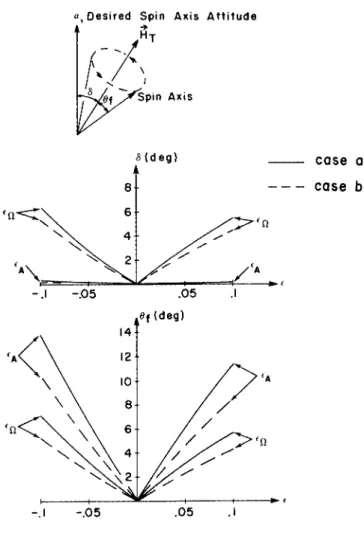
The preceding analysis was programmed digitally and runs were made for
case a: α = 9 0 ° , -φ = 1 8 0 ° (θ = 4 5 ° ) case b: α = 9 0 ° , θ = 6 0 ° (J = 1 0 9 . 5 ° )
for errors of +5 and + 1 0 % in Ω and A. These errors are desig- nated as eçi, £ a o n t n e graphs. It was also necessary to spec- ify the nominal ratio (C/A) ; this was chosen as 2 , which is representative of a disc. The results are plotted in Fig. 7 . The sketch at the top of Fig. 7 illustrates the definitions of
δ and 6 f .
The variable 6 is used generically in Fig. 7 ; thus eçi and 6 ^ appear on the same graph. In all cases when one parameter is varied, the other is held zero. Since δ , o f are necessarily always greater than zero, the cusps at the origin are not un- reasonable. The curves are symmetric with respect to either e only for sufficiently small values; otherwise there is an in- creasing asymmetry as £ increases. The effect of on δ is negligible, for the range considered, but quite pronounced on
^f. Conversely, £q affects δ and of about equally. Finally, it is noted that in all cases the errors are smaller when the nominal semiconical angle is 60 rather than 45° (the latter corresponds to the 180 precession). The reason is probably the reduced maneuver time which does not permit the various attitude errors to build up before the concluding impulse is applied. Presumably the errors could be further reduced if Θ were chosen still larger. As noted previously, the disadvan- tage of this is the increasing impulsive torque requirement.
No other runs of this type were made, as the objective was only to obtain an estimate of the effects of errors in two of the parameters for a nominal spin axis change, such as 90 .
The determination of the effect of finite torquing time is somewhat more involved. In the first place the typical as- sumption is made that the torque-time curve is a rectangular pulse whose area in units of torque time equals the impulsive torque. Thus, if the torquing time is called Τ and the torque magnitude T0, then by Eq. 1, one has always
Τ Τ = Ηο S tan θ [ΐδ]
Thus for a given Hs and 0, if τ increases, T0 decreases, and vice versa, in accordance with Eq. 18. Now for a given α and 0y the torquing rockets are located definitely on the body, so that when the rockets are firing the torque is a constant in body coordinates. This suggests the use of the Euler dynamic equations for determining the body rates. For moments of in- ertia A, A and C about the principal body axes xyz, these equations are
Αω + (C χ
Αώ + (A - C)o) ω = Τ [19]
y ν "7 \ 7 J L
Eqs. 19 must be solved in three regions. From Fig. 6 the com- ponents of T0 are obtained as
1) 0 < t < Τ
Τ = Τ cos 7 . χ ο ι Τ = Τ sin 7 .
y ο ι Α) ω ω = τ.
y ζ
C) 0 ) Ü3 = τ
Χ Ζ
Ccbz = 0
2) Τ < t < Τ (Τ = nominal delay time)
Τ = Τ = 0 x y 3) Τ < t < Τ + Τ
Τ = Τ cos 7. C
χ ο f Τ = Τ sin 7r
y ο f
The initial conditions, assuming a pure spin at t = 0, are
1) ω = ω = 0, ω = Ω
y χ y ζ
2) ω , ω continuous at t = τ ' χ y
3) ω , ω continuous at t = T.
' x y
These data then permit a solution for ω χ( ί ) and ^ ( t ) in the complete range 0 < t < T + T. It is noted that by the last of Eq. 19,ωζ Ξ Ω. The solutions to Eq. 19 satisfying these ini- tial conditions are simple and need not be explicitly given.
The second part of the problem is the determination of ve- hicle attitude given these body rates. It was decided to use Euler angles for this purpose. Now the spin axis attitude and total momentum vector at the conclusion of the torquing, t = Τ + T , are of course unique, whereas the choice of Euler angles is not unique.^ Thus, it seems unnecessary to go into the details of which system was chosen. It is sufficient to note than when the angles are determined by integration of the appropriate body rate, angle derivative equations, the direc- tion cosines of body fixed unit vectors can be determined by matrix transformation. In this way the spin axis attitude and
total momentum orientation are established with respect to the reference frame, the XYZ axes of Fig. 6. Since the desired spin axis attitude is also known with respect to this frame, then the angles δ and of, as previously defined, can be determined.
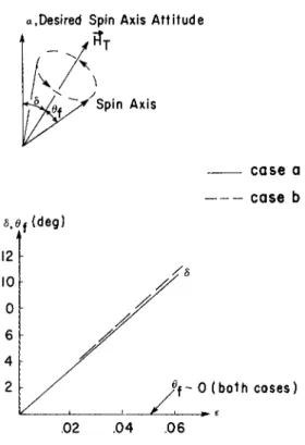
A digital program in accordance with the foregoing outline was set up. For the numerical examples the a and b cases treated previously were used again and τ was varied. The equations were nondimensionalized; the normalizing time used
bBy Euler angles is meant any set of three angles taken around successive positions of the body axes. One body axis can be used twice (the classical case) or each of the three body axes can be used once. For example, see (9).
w a s t h e n a t u r a l p e r i o d o b t a i n e d f r o m E q s . 19
Τ η 2π/ω
η [20]
w h e r e
le - A l ω Ω
η A
T h e d i m e n s i o n l e s s t o r q u i n g t i m e p a r a m e t e r t h e n i s
(τ/Τη) Ξ e [21]
I n t h e c a l c u l a t i o n s e w a s c h o s e n a s 0.02, 0.04, 0.06; ( C / A ) w a s c h o s e n a s 2; a n d a l l o t h e r p a r a m e t e r s w e r e n o m i n a l .
T h e r e s u l t s a r e p l o t t e d i n F i g . 8. I t is s e e n t h a t t h e a n g l e δ is v e r y n e a r l y l i n e a r w i t h £ a n d is v i r t u a l l y t h e s a m e f o r b o t h c a s e s . T h e a n g l e 0f w a s o f t h e o r d e r o f h u n d r e d t h s o f a d e g r e e , w h i c h m e a n s t h a t a t t h e c o n c l u s i o n o f t h e m a n e u - v e r t h e s p i n a x i s r e m a i n s v i r t u a l l y f i x e d i n s p a c e c o i n c i d e n t w i t h t h e t o t a l m o m e n t u m v e c t o r ; t h e t o t a l e r r o r t h e n i s d u e o n l y t o δ. I t is n o t e d t h a t t h e c a s e ε = 0.06 w i t h Θ = 60°
a n d ( C / A ) = 2 is r a t h e r e x t r e m e s i n c e f r o m E q s . 4, 8, 20, a n d
21
w h i c h m e a n s t h a t t h e t o r q u i n g t i m e i s a p p r o a c h i n g t h e d e l a y t i m e . I t i s p e r h a p s a l i t t l e s u r p r i s i n g t h a t t h e e r r o r is s t i l l n o m o r e t h a n a b o u t 11 a c c o r d i n g t o F i g . 8,
C O N C L U S I O N S
T h e b a s i c d y n a m i c s o f t h e t w o - i m p u l s e s c h e m e h a v e b e e n e x - a m i n e d w i t h r e g a r d t o p r e c e s s i o n a n g l e , c o n i c a l a n g l e , t o r q u e r e q u i r e m e n t s , a n d m a n e u v e r t i m e . F o r a g i v e n a t t i t u d e c h a n g e a n d c h o i c e of p r e c e s s i o n a n g l e o r c o n i c a l a n g l e it h a s b e e n s h o w n h o w t o l o c a t e b o d y f i x e d r o c k e t s . T h e e r r o r a n a l y s e s h a v e s h o w n t h a t r e a s o n a b l e t o l e r a n c e s i n a n l e a s t s o m e o f t h e s y s t e m p a r a m e t e r s a r e a l l o w e d i f t h e a c c u r a c y r e q u i r e m e n t s a r e n o t t o o s e v e r e . T h e p r o p o s e d s c h e m e i s w o r t h y o f f u r t h e r c o n -
s i d e r a t i o n a s a p r a c t i c a l m e a n s o f r e o r i e n t i n g t h e a t t i t u d e o f a s p i n n i n g , s y m m e t r i c v e h i c l e .
A C K N O W L E D G M E N T
T h e a u t h o r w i s h e s t o e x p r e s s h i s a p p r e c i a t i o n t o J o h n T i t u s a n d R o b e r t F r e u n d o f t h e N o r t r o n i c s R e s e a r c h S e c t i o n f o r a s - s i s t a n c e w i t h t h e d i g i t a l p r o g r a m m i n g .
(τ/Τ) = 0.79
660
REFERENCES
1 Windeknecht, Τ· G., "A simple system for sun orientation of a spinning satellite," Preprint 61-204-1898, National IAS-ARS Joint Meeting, Los Angeles, June 13-16, 1961.
2 Cole, R. D., Ekstrand, M. E. and O'Neill, M. R.,
"Attitude control of rotating satellites," ARS J. 31, 1446- 1447 (1961).
3 Adams, J. J., "Study of an active control system for a spinning body," NASA TN D-905, Langley Research Center, Langley Field, Virginia, June 1961.
4 Freed, L. Ε., "Attitude control system for a spinning body," Preprint 61-207-1901, National IAS-ARS Joint Meeting, Los Angeles, June 13-16, 1961.
5 Grasshoff, L. Η., "A method for controlling the attitude of a spin-stabilized satellite," ARS J· 31, 646-649 (1961).
6 v. Karman, T. and Biot, Μ. Α., Mathematical Methods in Engineering (McGraw-Hill Book Co., Inc., New York, 1940),
1st ed., pp. 85-87 .
7 Grubin, C , "Vector representation of rigid body rotation," American J. of Physics (to be published).
8 Whittaker, E. T., Analytical Dynamics (Dover Publications, New York, 1944), 4th ed., pp. 6-9,
9 Grubin, C , "On the schemes for describing the attitude of a rigid body," Space Technology Laboratories Rept.
TN-60-0000-09080, Los Angeles, Calif., May 1960, pp. 9-11.
Fig. 2 Precession geometry
t=0 +
Fig. 3 Precession dynamics (C > A) . a) Angular momenta;
b) angular velocities
t=0 +
t = 0 - H
(b)
F i g . 4 P r e c e s s i o n d y n a m i c s (C < A ) . a ) A n g u l a r m o m e n t a ; b ) a n g u l a r v e l o c i t i e s
Fig. 5 Comparison of constant cone angle vs. 180° precession, a) Impulse required; b) maneuver time
a, Desired Spin Axis Attitude
y^ ^ y s p i n Axis
5( d e g )
8
-
\ β
\ \
V 2
case a case b
-.1 -.05 .05 .1
Fig. 7 Effect of non-nominal parameters on system accuracy (a = 90°, C/A = 2)
a,Desired Spin Axis Attitude
Axis
case a case b
0f ~ 0 (both cases)
Fig. 8 Effect of finite torquing time on system accuracy (a =90°, C/A = 2)