COMPUTER SIMULATION OF ROUNDABOUTS
Tamás Kovács 1*
1 Department of Information Technology, GAMF Faculty of Engineering and Computer Science, John von Neumann University, Hungary
https://doi.org/10.47833/2020.3.CSC.003
Keywords:
traffic-simulator roundabout Article history:
Received 29 Sept 2020 Revised 18 Oct 2020 Accepted 25 Oct 2020
Abstract
In the last decades numerous traffic lamp controlled intersections have been changed to roundabouts on Hungarian traffic roads, hoping that this helps diminish the usual traffic jams in these traffic contexts. The most characteristic parameter of a roundabout is the capacity that is the number of vehicles can pass through the intersection in 1 hour. The capacity calculation of the new roundabouts, beyond a formula based calculation, often involves computer simulation as well, so as to get more reliable results. In the present paper we introduce a development of our traffic simulator so that it is able to determine the capacities of a roundabout. The simulation is tested by capacity calculation of a real roundabout and the dependency of the capacity on some key parameters is examined as well.
1 Introduction
Recently the role of computer simulators in traffic engineering has been growing gradually as more and more reliable and easy-to-use simulators appeared in the software market. These simulators give us cheap and quick answers about new intersections or urban traffic systems prior to expensive experiments and implementations. The roundabouts, being quite complex systems, are especially good objects of simulations. In the case of such intersections usually there is no programmed traffic light control, the capacities (i.e. the highest possible traffic currents for specific directions) are determined by the geometry of the roundabout, and the behavior of the drivers.
There are several mathematical models helping the capacity calculations for roundabouts. One part of these models formulates the highest possible (or average) vehicle speeds that belongs to the path-curves of the intersection. The other part describes the general behavior of the drivers waiting to enter the roundabout. Generally, the relation between the planned path-curves and maximum speed values are formulated by the national traffic planning guides or rules. So these rules can be somewhat different even in the European countries. Some of these rule-collections are published, see for example [1] (USA) or [2] (UK). However, researchers of the field analyzed the proposed
The simulator SIDRA employs deterministic mathematical models, while the systems RODEL and ARCADY use also empirical formulae. The other type is the so-called traffic micro-simulator that models each vehicle based on car-following and driver behavior equations. These equations contains also stochastic elements since the individual driver behaviors are probabilistic in nature.
The most known such a system is the VISSIM simulator, which is able to simulate not only roundabouts but a complex traffic contexts with different type of intersections and roads. The VISSIM handles the problem of speed-calculation in a unique way: does not calculates the maximum possible speed value for the curved road-segments, but leaves it to the VISSIM programmer to decide and set the average and maximal speed values for each segments. A detailed overview about these simulators and their capabilities can be read in [7].
Recently the author of the paper participated in developing a traffic micro-simulator that is based on the Intelligent Driver Model [8], and has similar capabilities to those of VISSIM. This simulator was validated by measurements at traffic-lamp controlled intersections [9]. In this paper a development work is introduced that makes it possible to apply this self-developed software for simulating roundabouts accurately. Only this self-developed simulator is used in this work. In the next section the main steps of the applied mathematical modelling are described. In Section 3 the simulation test, which is based on the geometry of a real roundabout, is introduced; and in the final section a brief conclusion of the work is given.
2 The mathematical model
In the speed calculation almost all of the mathematical models relies on the dynamic equilibrium equation on a zero elevation road-segment with curve-radius R:
𝑎𝑐𝑝=𝑣𝑅2= 𝜇𝑔 (1)
where acp is the centripetal acceleration, v is the tangential speed, g=8.81 m/s2 and µ is the side friction coefficient. This leads to:
𝑣𝑚𝑎𝑥(𝑖𝑛 𝐾𝑚/ℎ) = √127𝑅𝜇𝑚𝑎𝑥 (2)
The maximal values of the side friction are discussed by Akcelik in [6]; for a one-ton motor-car it is approximately 0.21. Thus, it seems that if the path-segment’s inscribed radius is known then the maximal (i.e. 0.85 percentile) and mean speed values are determined. Unfortunately, this is true only for traditional (i.e. not roundabout) intersections, because the central lane-width in a roundabout give possibility to the drivers to use different (optimal) paths on the same road-segment, depending on their turn direction. Similar to VISSIM, our traffic simulator is based on the link-connector model, that is, the road-segments (links) are connected by curved connector paths inside the intersections.
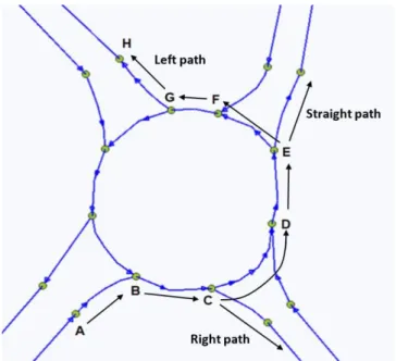
Though this model is more detailed than the simple link-node based models, this difference in the optimal paths causes difficulties in simulating a roundabout. Figure 1 shows an illustration of this problem.
Figure 1. Illustration of a link-connector modelled roundabout and the possible drive-through paths of the vehicles
For example, all vehicles arriving from south-west drives through the connector-endpoints A, B and C, but their path curvature, and hence the inscribed circle radius, are different. Similarly, between points C, D and E the straight-through driving and the left turning vehicles use different trajectories.
In our model the main deficiency is that the lane-width parameter is not considered in determining the maximum speeds. In the previous version of our simulator, the maximum speed value for a connector or road segment was determined by automatically calculating the smallest inscribed circle-radius and applying formula (2). In order to handle roundabouts, the maximum (i.e.
0.85 percentile) speed should be the function of not only the smallest inscribed circle but also the drive-through directions of the vehicles at hand, so, technically, the simple vmax(smallest_radius) function is replaced by the vmax(drive_direction) function. This replacement seems to be a simple task, however, requires a much more complex development work, since the parameters of the road- segments are static and known before the simulation, while the drive_direction parameter (i.e. right, straight or left) must be determined at the moment of vehicle’s arrival to the intersection for each vehicle. Similarly to VISSIM the maximum speed values were calculated a priory by determining the inscribed circle radii of the specific roundabout and using the tabulated speed values published by Akcelik in [6].
Beside path geometry, the other important parameter is the so called critical gap time. If the following time, which is the distance between two consecutive cars on the circular road divided by the velocity, is greater than the critical gap, then a unit car can drive onto the circular road from the approaching road, otherwise not. The value of this parameter is not universal, but can be different
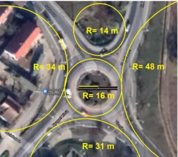
Figure 2. The satellite photograph (by Google) of the roundabout used for the test. The inscribed circles of the most often used paths are drawn by yellow lines.
Based on this geometry the applied average optimal-path speed values are shown in Table 1.
Table 1. The highest safe speed values for the test roundabout Directions Highest safe speed
North to West 28 km/h
East to North 18 km/h
South to East 34 km/h
West to South 27 km/h
All straight-through 36 km/h All left turning 21 km/h
In the test these speed-values and the critical gap values of 2.0; 3,0 and 4.0 secs were used.
Only the east-west straight-trough route capacity was examined with traffic volumes in the range of [100 .. 400] vehicles/hour. The only one traffic flow other than that was the south-north (i.e.
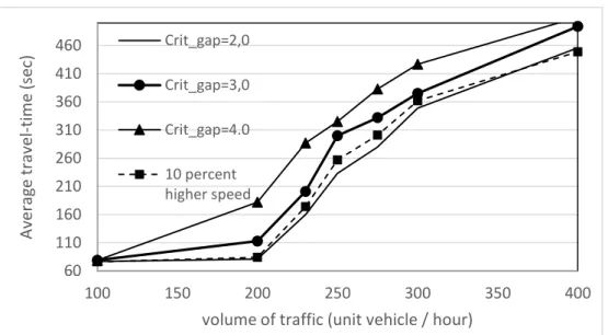
conflicting) traffic with volume 500 vehicles/hour. The measured quantity was the average travel time through the roundabout on the route at hand as the function of the traffic volume (we call this function as delay curve). The results are shown in Figure 3. The three delay curves drawn by continuous lines correspond to the three critical gap values, and the delay curve drawn by dashed line corresponds to the critical gap value of 3.0 sec but with mean speeds 10 percent higher than the values in Table 1.
Figure 3. The delay curves of one drive through route of the test roundabout.
The capacity of the intersection in this direction is often considered as the inflexion place of the delay curve, or the half-value place between the lower and the higher plateau. Using the former definition the capacity values in the examined cases are shown in Table 2. It seems that the capacity value is much more sensitive to the critical gap parameter than to the speed-values, so the ±3,3%
speed determination error can be considered as negligible. On the other hand the critical gap value belongs to this specific roundabout is a much more important parameter.
Table 2. Measured capacity values for the examined cases Case Capacity value (veh/h) Critical gap = 2.0 sec 245 ± 5
Critical gap = 3.0 sec 230 ± 5 Critical gap = 4.0 sec 210 ± 5 Critical gap = 3.0 sec, and
10% higher mean speeds
240 ± 5
4 Conclusion and future work
Based on the development work and the test measurements we can conclude the followings:
- a link-connector type microscopic traffic simulator can be used for correctly simulating roundabouts by using multiple optimal speed values for the path segments depending on
60 110 160 210 260 310 360 410 460
100 150 200 250 300 350 400
Average travel-time (sec)
volume of traffic (unit vehicle / hour) Crit_gap=2,0
Crit_gap=3,0 Crit_gap=4.0 10 percent higher speed
[1] US Department Of Transportation Contents : Roundabouts-An Informational Guide,
https://www.fhwa.dot.gov/publications/research/safety/00067/00067.pdf (Accessed 6 October 2020)
[2] Highways Agency (HA). Geometric Design of Roundabouts. Design Manual of Roads and Bridges. Available at:
https://www.standardsforhighways.co.uk/prod/attachments/2b5901c6-3477-4826-b780-cf99003fb5e0 (Accessed 6 October 2020).
[3] Bassani, M. and E. Sacchi. “Experimental Investigation into Speed Performance and Consistency of Urban Roundabouts: an Italian Case Study.” Poster Session at the “3rd International Conference on Roundabouts”
Transportation Research Board, Carmel, Indiana, USA, May 2011.
[4] Al-Omari, Bashar H., Khalid A. Ghuzlan, and Lina B. Al-Helo. "Modeling through traffic speed at roundabouts along urban and suburban street arterials." Journal of the Transportation Research Forum. Vol. 53. No. 1424-2016- 117957. 2014., DOI: 10.22004/ag.econ.207432
[5] Šurdonja, Sanja, Vesna Dragčević, and Aleksandra Deluka-Tibljaš. "Analyses of maximum-speed path definition at single-lane roundabouts." Journal of traffic and transportation engineering (English edition) 5.2 (2018): p. 83-95., https://doi.org/10.1016/j.jtte.2017.06.006
[6] Akcelik, R. "Estimating negotiation radius, distance and speed for vehicles using roundabouts. Akcelik & Associates Pty Ltd." 24th Conference of Australian Institutes of Transport Research. 2004.
[7] Gallelli, Vincenzo, and Rosolino Vaiana. "Roundabout intersections: evaluation of geometric and behavioural features with VISSIM." Proceedings of TRB National Roundabout Conference. Kansas City, Missouri, USA. 2008.
[8] Kesting, Arne, Martin Treiber, and Dirk Helbing. "Enhanced intelligent driver model to access the impact of driving strategies on traffic capacity." Philosophical Transactions of the Royal Society A: Mathematical, Physical and Engineering Sciences 368.1928 (2010): 4585-4605., https://doi.org/10.1098/rsta.2010.0084
[9] Kovács, T., Bolla, K., Alvarez Gil, R., Csizmás, E., Fábián, Cs., Kovács, L., Medgyes, K., Osztényi, J., Végh, A., 2016, Parameters of the intelligent driver model in signalized intersections, Technical Gazette, 23, No. 5, 1469-1474., https://doi.org/10.17559/TV-20140702174255