Discrete-Time Implementation and
Experimental Validation of a Fractional Order PD Controller for Vibration Suppression in Airplane Wings
Silviu Folea*, Robin De Keyser**, Isabela R. Birs*, Cristina I.
Muresan*, Clara Ionescu**
* Department of Automation, Technical University of Cluj-Napoca,
Memorandumului 28, Cluj-Napoca, Romania, e-mails: Silviu.Folea@aut.utcluj.ro, Isabela.Birs@aut.utcluj.ro, Cristina.Muresan@aut.utcluj.ro
** Department of Electrical energy, Systems and Automation, Ghent University, Technologiepark 914, Gent, Belgium, e-mail: Robain.DeKeyser@UGent.be
Abstract: Vibrations in airplane wings have a negative impact on the quality and safety of a flight. For this reason, active vibration suppression techniques are of extreme importance.
In this paper, a smart beam is used as a simulator for the airplane wings and a fractional order PD controller is designed for active vibration mitigation. To implement the ideal fractional order controller on the smart beam unit, its digital approximation is required. In this paper, a new continuous-to-discrete-time operator is used to obtain the discrete-time approximation of the ideal fractional order PD controller. The efficiency and flexibility, as well as some guidelines for using this new operator, are given. The numerical examples show that high accuracy of approximation is obtained and that the proposed method can be considered as a suitable solution for obtaining the digital approximation of fractional order controllers. The experimental results demonstrate that the designed controller can significantly improve the vibration suppression in smart beams.
Keywords: fractional order controller; novel indirect discretization method; smart beam;
vibration attenuation; experimental results
1 Introduction
A cantilever beam equipped with sensors and actuators is considered to be “smart”
since its dynamics are always known. This offers countless possibilities to control the amplitude and frequency of the beam’s movement, while also eliminating undesired vibration. The advantages of such an approach have endless practical uses, especially in the case of an airplane wing, which is continuously subjected to
random, unwanted vibrations caused by turbulences, engine vibration and trajectory changes [1].
The displacement of the free end of the beam can be successfully reduced with a variety of controllers, from fractional order to integer order PI, PD and PID, from Fuzzy Logic to Linear Quadratic Regulator, from adaptive to robust; and any hybrid combination between them [2]. In addition, optimization algorithms to compute the controller’s parameters such as Particle Swarm Optimization and Genetic Algorithms haven’t been neglected in the study of vibration suppression [3]. A tuning procedure based on reducing the resonant peak on the frequency magnitude plot is successfully presented in [4]. Apart from classical tuning procedures and optimization techniques, using neural networks is also a viable approach [5], [6].
Over previous decades, the popularity of the fractional order controllers has increased considerably. The fractional order approach represents a generalization of differentiation and integration to an arbitrary order. Compared to the integer order controllers, the fractional order ones offer increased flexibility and can honor more closed loop performance constraints simultaneously [7]. For this reason, a fractional order PD controller has been previously designed for a similar cantilever beam, as the case study in this paper, and the experimental results demonstrated the advantages of using a fractional order PD controller instead of the classical integer order PD [8], [9].
One of the key characteristics of fractional order systems is the hereditary effect, which offers an accurate mathematical representation of the dynamics of several phenomena. However, at the same time, because of their unlimited memory, fractional order systems cannot be exactly implemented [10] and thus, they require a proper rational approximation [11], [12], [13] in a limited frequency range [14]. In this paper, a fractional order PD controller is designed for vibration suppression. Its implementation, on a real time controller, requires the discrete- time approximation of the ideal fractional order control algorithm. To achieve this, the indirect discretization method proposed in [14] is used. First, the well-known Oustaloup Recursive Approximation method is employed to obtain a continuous- time approximation for the fractional order controller. Next, to obtain the discrete- time approximation, a new continuous-to-discrete time operator is proposed as an interpolation between the Euler and Tustin rules, allowing for the possibility of shaping the discrete-time transfer function through the use of a weighting parameter to better approximate the original fractional order system phase or magnitude. The purpose of this paper is to show that the proposed discrete-time approximation method is simple and efficient, not just in simulation environments, but also for real-time implementation of fractional order controllers and even for processes that exhibit a fast dynamic.
The paper is structured as follows. Section II presents the tuning procedure for a fractional order PD controller for vibration suppression in a smart beam. Section
III presents the proposed continuous-to-discrete-time operator, as well as the inverse operator. The mapping between the continuous-time and discrete-time poles/zeros is given, as well as numerical examples to show the flexibility, as well as the problems that can be avoided through the use of the new operator, compared to the classical Tustin rule. Section IV consists in the case study: the vibration attenuation in a smart beam, and details the design and discrete-time implementation of a fractional order controller. Experimental results are also provided. The last section includes the concluding remarks.
2 Tuning of a Fractional Order Controller for Vibration Suppression
To suppress unwanted vibrations that may occur in a smart beam, a fractional order PD controller is designed:
𝐻𝐹𝑂−𝑃𝐷(𝑠) = 𝑘𝑝(1 + 𝑘𝑑𝑠𝜇) (1) where kp and kd are the proportional and the derivative gains, respectively, while μϵ[0,1] is the fractional order of differentiation. The frequency domain representation of (1) is obtained as:
𝐻𝐹𝑂−𝑃𝐷(𝑗𝜔) = 𝑘𝑝[1 + 𝑘𝑑𝜔𝜇(𝑐𝑜𝑠 (𝜋𝜇2) + 𝑗𝑠𝑖𝑛 (𝜋𝜇2))] (2) The design of the fractional order controller in (1) is based on imposing three different frequency domain specifications [15], [16], regarding the gain crossover frequency ωcg, the phase margin of the open loop system φm and the iso-damping property. The three performance specifications are mathematically expressed as:
∠ (𝐻𝑜𝑝𝑒𝑛−𝑙𝑜𝑜𝑝(𝑗𝜔𝑐𝑔)) = −𝜋 + 𝜑𝑚 (3)
|𝐻𝑜𝑝𝑒𝑛−𝑙𝑜𝑜𝑝(𝑗𝜔𝑐𝑔)| = 1 (4)
𝑑(∠𝐻𝑜𝑝𝑒𝑛−𝑙𝑜𝑜𝑝(𝑗𝜔))
𝑑𝜔 |
𝜔=𝜔𝑐𝑔
= 0 (5)
Assuming the smart beam is mathematically modeled through a transfer function G(s), then the equations (3)-(5) can be further described as:
|𝑘𝑝[1 + 𝑘𝑑𝜔𝑐𝑔𝜇
(𝑐𝑜𝑠 (𝜋𝜇2) + 𝑗𝑠𝑖𝑛 (𝜋𝜇2))]| =|𝐺(𝑗𝜔1
𝑐𝑔)| (6)
𝑘𝑑𝜔𝑐𝑔𝜇𝑠𝑖𝑛(𝜋𝜇2)
1+𝑘𝑑𝜔𝑐𝑔𝜇𝑐𝑜𝑠(𝜋𝜇2)= 𝑡𝑔 (−𝜋 + 𝜑𝑚− ∠𝐺(𝑗𝜔𝑐𝑔)) (7)
𝜇𝑘𝑑𝜔𝑐𝑔𝜇−1𝑠𝑖𝑛(𝜋𝜇2)
= −𝑑(∠𝐺(𝑗𝜔))| (8)
Equations (7) and (8) can then be used to determine the controller parameters kd and μ based on a graphical approach [15, 16, 17], in which the derivative gain is computed as a function of the fractional order according to (7) kd1=f(μ) and according to (8) kd2=g(μ). Then, the two functions f and g are plotted, with the final values for kd and μ determined as the intersection point of f and g. The proportional gain kp can be determined afterwards based on the modulus equation in (6).
3 The Proposed Approximation Method
To implement the fractional order PD controller in (1), an indirect discretization method is proposed [14]. The approximation method consists in two steps: the first one involves the continuous-time fitting of the ideal fractional order PD controller with a higher order rational transfer function, while the second step requires the discretization of this fitted continuous-time approximation using any of the well know discretization techniques [13]. Even though a lot of continuous- time approximation methods have been developed, in this paper the Oustaloup Recursive Approximation method [19] is used because of its wide acceptance and efficiency. According to this method, the continuous-time rational transfer function is obtained as follows:
𝐶(𝑠) = 𝐾𝑐
∏𝑚𝑗=1(𝑠−𝑧𝑗𝑐)
∏𝑛𝑖=1(𝑠−𝑝𝑖𝑐) (9)
where Kc is the gain, 𝑧𝑗𝑐 are the zeros, j=1,2,...,m and 𝑝𝑖𝑐 are the poles, i=1,2,…,n.
The poles and zeros are obtained based on a recursive distribution between a low and a high frequency, at well-chosen intervals, such that a constant ratio is obtained between two consecutive poles and zeros [19].
To obtain the digital approximation of the fractional order PD controller, the second step implies the discretization of (9). Instead of using the classical discretization rules, such as Euler, Tustin, Simpson, Al-Alaoui, etc., a new continuous-to-discrete-time operator is applied [14]:
𝑠 =1+𝛼𝑇 1+𝛼𝑧1−𝑧−1−1=1+𝛼𝑇 𝑧−1𝑧+𝛼 (10) with the inverse operator obtained directly from (10):
𝑧 =1+𝛼+𝛼𝑠𝑇1+𝛼−𝑠𝑇 (11) where T is the sampling time. The proposed operator is an interpolation between the Euler and the Tustin discretization rules, with αϵ[0,1] being a weighting parameter. The Euler discretization rule is obtained if α=0, while α=1 leads to the Tustin rule.
The poles, 𝑝𝑖𝑑, and zeros, 𝑧𝑗𝑑, of the discrete-time transfer function in (14) are computed according to the inverse operator in (11):
𝑝𝑖𝑑=1+𝛼+𝛼𝑝1+𝛼−𝑝𝑖𝑐𝑇
𝑖𝑐𝑇 (12) 𝑧𝑗𝑑=1+𝛼+𝛼𝑧1+𝛼−𝑧𝑗𝑐𝑇
𝑗𝑐𝑇 (13) Then, the discrete-time equivalent of (9) has the form:
𝐶(𝑧) = 𝐾𝑑∏∏𝑛𝑗=1(𝑧−𝑧(𝑧−𝑝𝑗𝑑)
𝑖𝑑)
𝑛𝑖=1 (14)
where Kd is the corresponding discrete-time transfer function gain and it is computed based on the equivalency of the continuous-time and discrete-time transfer functions from (9) and (14) in steady state (s=0 and z=1):
𝐾𝑑= 𝐾𝑐
∏𝑚𝑗=1(−𝑧𝑗𝑐)∏𝑛𝑖=1(1−𝑝𝑖𝑑)
∏𝑛𝑖=1(−𝑝𝑖𝑐)∏𝑛𝑗=1(1−𝑧𝑗𝑑) (15) Remarks [14]:
1) To calculate the discrete-time gain Kd using (15) it is necessary to remove first all pure integrators and differentiators.
2) A continuous-time transfer function with dead time can be converted in two steps. The rational part is converted using (12), (13) and (14), while the dead time is converted separately to the nearest integer number of samples: 𝑒−𝑠𝜏𝑑↔ 𝑧−𝑑 with 𝜏𝑑≅ 𝑑𝑇.
3) If m<n, then (n-m) continuous-time zeros at -∞ are converted into discrete-time zeros at –α. In this case, (n-m) zeros are added in discrete-time: 𝑧𝑗𝑑= −𝛼 with 𝑗 = 𝑚 + 1, 𝑛̅̅̅̅̅̅̅̅̅̅̅ .
Figs. 1 a) and b) show the frequency response of the ideal continuous-time fractional order system s-0.35, as well as the discrete-time approximations. The Oustaloup Recursive Approximation method has been used to compute the continuous-time rational transfer function, with the maximum and minimum frequency bounds taken as ωh=10 and ωl=10-2, with a total of 5 poles and zeros.
The sampling time used in the discretization is T=0.314 s and the weighting parameter has been taken as α=0.9 in Fig. 1a) and α=0.2 for Fig. 1b).
The frequency responses in Fig. 1 demonstrate that the lower the value for α, the better the discrete-time approximation of the magnitude curve. On the other hand, a higher value for α improves the approximation of the phase curve. However, if α is selected close to 1, problems could arise in the discrete-time approximation.
The next numerical example demonstrates this issue.
a) b) Figure 1
Frequency responses of s-0.35 for a) α=0.9; b) α=0.2 Consider the fractional order PID controller:
𝐻𝐹𝑂−𝑃𝐼𝐷(𝑠) = 10 + 20𝑠−0.2+ 2𝑠0.7 (16) The Oustaloup Recursive Approximation method, with 5 poles and zeros and within the frequency interval ωϵ(101, 102), is used to approximate the fractional order integrator and differentiator in (16). The discrete-time approximation is then computed with a sampling time T=0.0314 and two different values for the weighting parameter, α=0.3 and α=1, respectively. Fig. 2 shows the frequency responses of the ideal fractional order controller in (16), along with the two discrete-time approximations corresponding to the two different choices for α. The step responses of the two controllers are given in Fig. 3. As indicated here, when α=1, the ringing phenomenon occurs. Ringing of the controller output is usually unwanted in practice because of its wear effect on the actuators.
Figure 2
Frequency responses of a fractional order PID controller: ideal vs. discrete-time approximations using the proposed method
10-2 10-1 100 101
Magnitude (dB)
-20 -10 0 10 20
Frequency (rad/s)
10-2 10-1 100 101
Phase (o) -30 -20 -10
0 FO system Discrete-time approx
10-2 10-1 100 101
Magnitude (dB)
-20 -10 0 10
20 FO system
Discrete-time approx
Frequency (rad/s)
10-2 10-1 100 101
Phase (o) -30 -20 -10 0
101 102
20 30 40 50
Magnitude (dB) FO system
Discrete-time approx, =0.3 Discrete-time approx, =1
101 102
-20 0 20 40 60
Frequency (rad/s) Phase (o)
Figure 3
Step responses of the discrete-time approximations of a fractional order PID controller using different values for α
As a conclusion, it is usually bad practice to convert a continuous-time fractional order system (obtained according to the Oustaloup Recursive Approximation method) to its discrete-time equivalent by taking the weighting parameter α close to 1. A fortiori, taking α=1 (Tustin) should be avoided. A theoretical explanation of the cause of the ringing phenomenon is given in [14].
4 Case Study
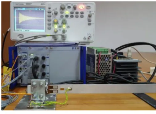
A smart beam system is considered, in this paper, as the case study. An experimental laboratory scale smart beam unit was developed and built at the Technical University of Cluj-Napoca in Romania, (Fig. 4).
Figure 4 The experimental stand
0 0.5 1 1.5 2
10 15 20 25 30 35 40 45 50
55 Step Response
Time (sec)
Amplitude
=1
=0.3
4.1 Hardware Setup
The block diagram of the system, including the programmable automation controller and a dedicated system with power amplifier (E503.00), the signal processing module (E509.X3), chassis (E501.00), the smart beam, two actuators PZT (P-878.A1) and two piezo resistive sensors (1-LY11-3/120) placed on both sides of the smart beam is presented in Fig. 5.
Figure 5
Block diagram of the experimental stand
The PAC embedded system used for implementation is a reconfigurable control and acquisition system providing high performance and reliability. The device includes a real time controller (NI 9014), a chassis with FPGA (NI 9103), two extension modules with analog input lines (NI 9230) and analog output lines (NI 9263).
The architecture of the embedded system is built around two chips: the first one, which runs the VxWorks real-time operating system and is programmable with LabVIEWTM Real Time, and the second which is programmable through LabVIEWTM FPGA.
The real time controller is used for control purposes and is based on an industrial 400 MHz Free scale processor for deterministic and reliable real-time applications. An advantage of this processor is the support for floating point calculations, which is necessary for the control algorithm chosen, having 128 MB of DRAM memory and 2 GB of nonvolatile storage.
The programmable chassis module harbors the user-programmable Virtex II FPGA, which will be used to implement all time critical operations and data acquisition. The input module provides connections for three differential analog input channels. It includes a 24-bit analog-to-digital converter (ADC), is dedicated for piezoelectric sensors and is compatible with TEDS sensors. The NI 9263 provides 4 analog output channels and is used for the command signal applied to the power amplifier and PZT.
4.2 System Identification
The transfer function of the process was determined experimentally by applying a sine wave excitation to the two actuators attached near the fixed end of the beam.
By applying a swept sine with varying frequency between 5 and 100 Hz, it was experimentally observed that the largest vibration amplitude is obtained around 14.5 Hz which is the resonant frequency characterizing the first flexural mode.
A second order model for the process was determined exciting the beam with a sine wave of amplitude 1V and 14.5 Hz.
𝐺(𝑠) =𝑠2+1.221 𝑠+822278.35 (17) Figs. 6, 7 and 8 show the experimental data used in the identification, as well as a zoomed view of the transient and steady state responses. A 93.22% fit over the experimental data has been obtained using the mathematical model in (17).
Obtaining such a high similarity between the identified model and the experimental data doesn’t justify the effort necessary to approximate the dynamics of the process with a higher order model.
A swept sine of 1V amplitude and a frequency range between 12 and 16 Hz has also been applied to the smart beam. The simulated and experimental data in Fig.
9 show a good accuracy for the mathematical model with a 73.66% fit.
Figure 6
Validation of the identified transfer function on a sine excitation with amplitude 1 and frequency 14.5 Hz
Time (seconds)
0 0.5 1 1.5 2 2.5 3 3.5 4
Amplitude
-0.5 -0.4 -0.3 -0.2 -0.1 0 0.1 0.2 0.3 0.4 0.5
sinus 14.5 Hz G(s)
Figure 7 Zoomed transient regime
Figure 8 Zoomed steady-state regime
Time Response Comparison
Time (seconds)
Amplitude
0.8 1 1.2 1.4 1.6 1.8 2 2.2 2.4 2.6
-0.5 -0.4 -0.3 -0.2 -0.1 0 0.1 0.2 0.3 0.4 0.5
sinus 14.5 Hz G(s)
Time (seconds)
3.9 3.92 3.94 3.96 3.98 4 4.02
Amplitude
-0.5 -0.4 -0.3 -0.2 -0.1 0 0.1 0.2 0.3 0.4
0.5 sinus 14.5 Hz
G(s)
Figure 9
Comparison of actual smart beam response and mathematical model for a swept sine response
4.3 Controller Tuning and Experimental Results
To tune the fractional order PD controller for the smart beam modeled as indicated in (17), the following performance specifications are imposed: a) a gain crossover frequency ωcg=105 rad/s, b) the phase margin φm=60o and the iso-damping property. The graphical solution for equations (7) and (8) is given in Fig. 10. The intersection point in Fig. 10 gives kd=0.0308 and μ=0.9043. Based on the modulus condition in (6), the proportional gain kp =14.736. The transfer function of the fractional order PD controller is then:
𝐻𝐹𝑂−𝑃𝐷(𝑠) = 14.736(1 + 0.0308𝑠0.9043) (18)
Figure 10
Graphical solution for fractional order PD controller parameters: kd and μ Time (seconds)
0 5 10 15 20 25
Amplitude
-0.6 -0.4 -0.2 0 0.2 0.4 0.6
swept sine 12 to 16 Hz G(s)
The Oustaloup Recursive Approximation method is used to obtain the continuous- time rational transfer function, within the frequency range ωϵ(0.0638, 628):
𝐶(𝑠) =1248.8 (𝑠+468.3) (𝑠+58.64) (𝑠+18.23) (𝑠+1.368) (𝑠+0.08718)
(𝑠+5505) (𝑠+347.3) (𝑠+21.92) (𝑠+1.383) (𝑠+0.08725) (19) The discrete-time approximation, based on the proposed method, is obtained with α=0.2 and a sampling time T=0.005 seconds:
𝐺(𝑧) = 77.175(𝑧−0.206)(𝑧−0.764)(𝑧−0.915)(𝑧−0.993)(𝑧−0.9996)
(𝑧+0.15)(𝑧−0.29)(𝑧−0.89)(𝑧−0.993)(𝑧−0.9995) (20) The Bode diagrams of the ideal fractional order PD controller in (18), along with its discrete-time approximation in (20), are given in Fig. 11 showing a good similarity between the two frequency responses. The discrete-time controller in (20) is then implemented on the smart beam. The experimental results considering a tip displacement of the beam’s free end are given in Fig. 12, while Fig. 13 shows the free response of the beam considering the same initial tip displacement. The settling time for the free response is 6.88 seconds; as indicated in Fig. 12, the settling time for the controlled response is reduced to 2.92 seconds, which is less than a half.
Figure 11
Bode diagrams of the ideal fractional order PD controller and its discrete-time approximation
100 101 102
Magnitude (dB)
20 25 30 35 40 45
Frequency (rad/s)
100 101 102
Phase (o)
-20 0 20 40 60 80
Ideal fractional order PD controller Discrete-time approximation
Figure 12
Vibration attenuation using fractional order PD controller
Figure 13
Free response of the smart beam Conclusions
Suppressing unwanted vibrations are a key concern in numerous industrial domains, including the aerospace industry. Smart structural beams are generally considered an accurate means of studying the behavior of airplane wings.
Numerous active vibration control strategies have been proposed, analyzed and experimentally tested, with a new focus on fractional order control algorithms. In this paper, a fractional order PD controller is designed for such a purpose. The major disadvantage of such controllers is that their unlimited memory causes problems when it comes to the actual implementation of the controllers on real environments. The solution to this problem consists in the proper, rational approximation of these fractional order controllers.
Time (seconds)
0 2 4 6 8 10 12
Amplitude
-0.6 -0.4 -0.2 0 0.2 0.4 0.6 0.8
Active vibration suppression
Time (seconds)
0 2 4 6 8 10 12
Amplitude
-0.4 -0.2 0 0.2 0.4 0.6
Uncompensated vibration
In this paper, a novel indirect approach to compute a rational discrete-time approximation of the fractional order PD controller is used. The preliminary results of using this new method have been presented in [14]. The first step consists in obtaining a rational continuous-time transfer function according to the Oustaloup Recursive Approximation method. Then, the new continuous-to- discrete-time operator is used to compute the digital transfer function. The new operator is an interpolation between the Euler and Tustin rules, which ensures an increased flexibility in guaranteeing a better fitting of the magnitude or phase curve of the original fractional order controller. Numerical examples are provided to point out the advantages of this new operator.
Furthermore, this paper presents and demonstrates that the proposed discrete-time approximation method is simple and efficient, not just in simulation environments, but also for real-time implementation of fractional order controllers and even for processes that exhibit a fast dynamic. In this regard, the case study presented shows that the use of this new operator in the approximation of a fractional order PD controller leads to a discrete-time rational transfer function that can be further implemented on the dedicated real time control device. The experimental results, obtained using this discrete-time approximation of the fractional order PD controller, demonstrate the efficiency of the designed algorithm, providing for a 57.5% improvement in the vibration suppression.
Acknowledgement
This work was supported by a grant of the Romanian National Authority for Scientific Research and Innovation, CNCS – UEFISCDI, project number PN-II- RU-TE-2014-4-0598, TE 86/2015.
References
[1] H. A. Abdulameer, H. R. Wasmi: “Vibration Control Analysis of Aircraft Wing by Using Smart Material”, Innovative Systems Design and Engineering, Vol. 6, No. 8, pp. 7-42, 2015
[2] I. Birs, S. Folea, D. Copot, O. Prodan, C. I. Muresan: “Comparative Analysis and Experimental Results of Advanced Control Strategies for Vibration Suppression in Aircraft Wings”, The 13th European Workshop on Advanced Control and Diagnosis, Lille, France, November 17-18 2016 [3] M. Marinaki, Y. Marinakis, G. E. Stavroulakis, "Fuzzy Control Optimized
by PSO for Vibration Suppression of Beams”, Control Engineering Practice, Vol. 18, No. 6, pp. 618-629, 2010
[4] I. Birs, C.I. Muresan, S. Folea, O. Prodan, L. Kovács: “Vibration Suppression with Fractional-Order PIλDµ Controller”, Proceedings of the 2016 IEEE International Conference on Automation, Quality and Testing, Robotics (AQTR), Cluj-Napoca, Romania, May 19-21 2016
[5] Z. Qiu, X. Zhang, C. Ye: "Vibration Suppression of a Flexible Piezoelectric Beam using BP Neural Network Controller," Acta Mechanica Solida Sinica, Vol. 25, No. 4, pp. 417-428, 2012
[6] O. Abdeljaber, O. Avci, D. J. Inman, "Active Vibration Control of Flexible Cantilever Plates using Piezoelectric Materials and Artificial Neural Networks", Journal of Sound and Vibration, Vol. 363, pp. 33-53, 2016 [7] C. A. Monje, Y. Q. Chen, B. M. Vinagre, D. Xue, V. Feliu, “Fractional
order Systems and Controls: Fundamentals and Applications”, Springer- Verlag, London, 2010
[8] I. R. Birs, C. I. Muresan, S. Folea, O. Prodan: “A Comparison between Integer and Fractional Order PDµ Controllers for Vibration Suppression”, Applied Mathematics and Nonlinear Sciences, Vol. 1, No. 1, pp. 273-282, 2016
[9] Cristina Muresan, Isabela Birs, Silviu Folea, Ovidiu Prodan; “Experimental Results of a Fractional Order PDλ Controller for Vibration Suppresion”, 14th International Conference on Control, Automation, Robotics and Vision, ICARCV 2016, November 13-15, Phuket, Thailand
[10] Charef, T. Bensouici, “Design of Digital FIR Variable Fractional Order Integrator and Differentiator”, Signal, Image and Video Processing, Vol. 6, No. 4, pp. 679-689, 2012
[11] T. Krishna, “Studies on Fractional Order Differentiators and Integrators: A Survey”, J. Signal Proc., Vol. 91, No. 3, pp. 386-426, 2011
[12] G. Maione, “Closed-Form Rational Approximations of Fractional, Analog and Digital Differentiators/Integrators”, IEEE Journal On Emerging And Selected Topics In Circuits And Systems, Vol. 3, No. 3, pp. 322-329, 2013 [13] R. El-Khazali, “Discretization of Fractional-Order Differentiators and
Integrators”, Preprints of the 19th World Congress, Cape Town, South Africa. August 24-29, pp. 2016-2021, 2014
[14] De Keyser, R., Muresan, C. I., An Analysis of a New Continuous-to- Discrete Time Operator for the Approximation of Fractional Order Systems, Workshop on Women in Egineering, 2016 IEEE International Conference on Systems, Man, and Cybernetics (SMC 2016), Budapest, Hungary, 9-12 October 2016
[15] Copot, C., Muresan, C. I., Ionescu, C. M., De Keyser, R. (2014), Fractional Order Control of a DC Motor with Load Changes, 14th International Conference on Optimization of Electrical and Electronic Equipment OPTIM, pp. 956-961, DOI: 10.1109/OPTIM.2014.6850964, May 22-24, Bran, Romania
[16] C. I. Muresan, S. Folea, G. Mois, E. H. Dulf, “Development and Implementation of an FPGA Based Fractional Order Controller for a DC Motor”, Journal of Mechatronics, Vol. 23, no. 7, pp.798-804, 2013
[17] Muresan, C. I., Dulf, E. H., Both, R. (2016) Vector-based Tuning and Experimental Validation of Fractional Order PI/PD Controllers, Journal of Nonlinear Dynamics, DOI: 10.1007/s11071-015-2328-2, Vol. 84, No. 1, pp. 179-188
[18] Petras, “Tuning and Implementation Methods For Fractional-Order Controllers”, Fractional Calculus and Applied Analysis, Vol. 15, No. 2, pp.
282-303, DOI: 10.2478/s13540-012-0021-4, 2012
[19] Oustaloup, A., F. Levron, B. Mathieu, F. M. Nanot, “Frequency-Band Complex Noninteger Differentiator: Characterization and Synthesis”, IEEE Trans. Circuits Syst. I Fundam. Theory Appl., Vol. 47, No. 1, pp. 25-39, 2000