Contents lists available atScienceDirect
Applied Surface Science
journal homepage:www.elsevier.com/locate/apsusc
Full Length Article
Carbon nanosphere templates for the preparation of inverse opal titania photonic crystals by atomic layer deposition
László Péter Bakos
a,⁎, Dániel Karajz
a, András Katona
a, Klara Hernadi
b, Bence Parditka
c, Zoltán Erdélyi
c, István Lukács
d, Zoltán Hórvölgyi
e, Géza Szitási
f, Imre Miklós Szilágyi
aaDepartment of Inorganic and Analytical Chemistry, Budapest University of Technology and Economics, Szent Gellért tér 4, H-1111 Budapest, Hungary
bDepartment of Applied and Environmental Chemistry, University of Szeged, Rerrich Béla tér 1, H-6720 Szeged, Hungary
cDepartment of Solid State Physics, Faculty of Sciences and Technology, University of Debrecen, P.O. Box 400, H-4002 Debrecen, Hungary
dHungarian Academy of Sciences, Research Centre for Energy, Institute of Technical Physics and Materials Science, Konkoly Thege M. út 29-33, H-1121 Budapest, Hungary
eDepartment of Physical Chemistry and Materials Science, Budapest University of Technology and Economics, Budafoki út 8. F. I. Building, H-1111 Budapest, Hungary
fFemtonics Ltd, Tűzoltó utca 59, H-1094 Budapest, Hungary
A R T I C L E I N F O
Keywords:
Carbon nanospheres TiO2
Inverse opal photonic crystal Photocatalysis
A B S T R A C T
Carbon nanospheres were used as templates for thefirst time to prepare titania inverse opal photonic crystal.
From the spheres, opal colloid crystals were made by vertical deposition on microscope slides, and TiO2was grown on them using atomic layer deposition (ALD). For this technique, the relatively high thermal stability and the presence of oxygen containing functional groups on the surface of the carbon spheres are beneficial.
Subsequent annealing burned out the template spheres, leaving behind the inverse opal structures. The upper solid TiO2layer was removed with argon ion sputtering. The samples were characterized with SEM, Raman spectroscopy, XRD, EDX, UV–Vis diffuse reflectance spectroscopy and their photocatalytic activity was in- vestigated in decomposing organic dyes under UV and visible illumination. A new approach was used to test photocatalysis on the surface by utilizing UV–Vis reflectance and Raman spectroscopy in conjunction.
1. Introduction
Photonic crystals, particularly the inverse opal variants are in the center of many researches because of their favorable and tunable op- tical properties, which prevent the propagation of light in certain di- rections with specified frequencies[1,2]. They can be made from a wide variety of dielectric materials, e.g. silicon, silica, titania, ZnO or CdSe, with methods such as sol-gel technique, atomic layer deposition (ALD) or electrodeposition [3–8]. Among these materials, TiO2is a widely researched photocatalyst with a band gap of 3.2 eV (anatase form), however, since it absorbs only in the UV range, shifting its absorption to the visible region is preferred. Many approaches are tried for this purpose, such as doping with metal or non-metal elements (e.g. Au, Sn, C or N), using organic dyes for sensitization or making a composite material (for example, with carbon nanotubes or WO3)[9–17].
Creating inverse opal structure from the TiO2offers another method to shift the absorption to visible region without any chemical mod- ification through the slow photon effect. This phenomenon appears due to the interaction of the wave packet reflected by the photonic band gap
with the transmitted wave packet at wavelengths near the gap.
Consequently, a stationary wave packet is formed, which possess strongly reduced group velocity, so the lifetime of the photons and the optical path of the light wave increase in the inverse opal. This process helps the light absorption, thus increasing the photocatalytic activity [18–21]. Inverse opals can also be prepared by top-down methods, but bottom-up techniques are more convenient, as they take advantage of the colloidal self-assembly [22–24]. In these approaches, a colloid crystal is prepared from the template spheres, among which the most widely used are polystyrene, poly(methyl methacrylate) and silica, then the gaps between the spheres arefilled with the chosen dielectric ma- terial. For this purpose, ALD is a highly suitable technique as it ensures homogenous coating of the spheres[25–28]. Finally, the spheres are removed, leaving behind the inverse opal structure. The polymers can be burned out, and silica is usually removed by dissolving it with hy- drogenfluoride[29–31].
Our group showed previously that carbon nanospheres (CS) are suitable templates for the atomic layer deposition of TiO2, because they are thermally stable up to 300 °C in inert atmosphere and have oxygen
https://doi.org/10.1016/j.apsusc.2019.144443
Received 1 August 2019; Received in revised form 15 October 2019; Accepted 17 October 2019
⁎Corresponding author.
E-mail address:laszlobakos@hotmail.com(L.P. Bakos).
Available online 26 October 2019
0169-4332/ © 2019 The Authors. Published by Elsevier B.V. This is an open access article under the CC BY license (http://creativecommons.org/licenses/by/4.0/).
Please cite this article as: László Péter Bakos, et al., Applied Surface Science, https://doi.org/10.1016/j.apsusc.2019.144443
containing functional groups on their surface. By subsequent annealing of the CS-TiO2composites, hollow titania shells can be made[32]. In this work, by making an ordered face centered colloidal crystal from the carbon nanospheres, and depositing TiO2on it with ALD, inverse opal structures were fabricated. For reference, an inverse opal was prepared from polystyrene nanospheres, which is a widely used conventional template for this purpose. The carbon spheres were tested for thermal stability by thermogravimetry/differential thermal analysis (TG/DTA).
The inverse opal samples were investigated with scanning electron microscopy (SEM), Raman spectroscopy, X-ray diffraction (XRD), UV–Vis diffuse reflectance spectroscopy and their photocatalytic ac- tivity investigated in decomposing two organic dyes, methyl orange dye in solution, and methylene blue dye dried on the surface of the samples, both under UV and visible light irradiation.
2. Materials and methods
2.1. Preparation of the carbon nanospheres
The carbon nanospheres (CS) were prepared from sucrose solution by a hydrothermal method. The pH was alkaline, set to 11 with NaOH solution. The reaction went for 12 h at 180 °C in an autoclave. The re- sulting carbon nanospheres were washed with warm distilled water, then with ethanol-water mixture, and afterwards, five times with acetone. The resulting black powder was dried overnight at 70 °C. The average diameter of the spheres was 458 nm, with a standard deviation of 80 nm, which parameters were calculated from SEM images.
2.2. Preparation of the colloidal crystal
For reference, inverse opals were prepared from polystyrene spheres (PS) as well (10 wt% in water, 300 nm diameter, with a standard de- viation of 40 nm), which was bought from Sigma-Aldrich. The synthesis process was the same for both CS and PS. It started with making a 0.3 wt% suspension in distilled water, which was placed in an ultra- sonic bath for 2 h to separate the aggregated nanospheres. The sub- strates were microscope slides, cleaned with soap, ethanol, then held 1 h in piranha solution (mixture of cc. H2SO4and 30% H2O2, in 3:1 ratio) to remove any organic remnants and make the surface hydrophilic.
After that, the glass slides were placed vertically in 5 ml suspensions of the CS and PS. They were put in a furnace at 50 °C for 14 h, so the colloidal crystal could form during the evaporation of the water through colloidal self-assembly, and werefinally heated to 80 °C for 1.5 h.
2.3. Atomic layer deposition
The CS and PS colloidal crystals on the glass substrates were put in a Beneq TFS-200-186 flow ALD machine. The atomic layer deposition (ALD) of the TiO2was performed at 50 °C, the pressure was 1 mbar in the reaction chamber. One deposition cycle was 0.3 s pulse of TiCl4
precursor, 3 s nitrogen purge, 0.3 s pulse of H2O and 3 s nitrogen purge, and this cycle was repeated for 700 times. A clean glass substrate was placed alongside the samples during the ALD, and the thickness of the deposited oxide layer was measured on it by profilometry to be 55 nm.
2.4. Obtaining the inverse opal
The nanosphere-TiO2 composites were annealed in air in a Nabertherm L9/11/B410 furnace, i.e. heated to 500 °C under 4 h, and stayed at that temperature for 2 h. This process burnt out the CS and PS, leaving behind the TiO2inverse opal structure. Finally, the inverse opals were sputtered for 100 min at 20 A current with argon ions in a Leybold Heraeus instrument to remove upper solid TiO2layer to get the underlying inverse opal structure.
2.5. Characterization
TG/DTA measurements of the carbon spheres were made in a TA Instruments SDT 2960 machine, with a heating rate of 10 °C/min until 900 °C, under 130 cm3/min gasflow. The measurement under nitrogen flow simulated the environment in the ALD reactor, and the data in air gave information about the annealing process.
For the SEM images, a LEO 1540 XB scanning electron microscope was used, in high vacuum mode with a secondary electron detector.
Adhesive carbon tapes were used tofix the samples on a copper sample holder. To prevent the carbon and polystyrene nanosphere opals from charging, they were sputtered with an Au/Pd layer, which step was unnecessary for the TiO2inverse opals.
EDX spectra were measured on a JEOL JSM-5500LV scanning electron microscope, and three EDX measurements were averaged for each sample.
Raman spectra were taken on a Jobin Yvon Labram Raman spec- troscope equipped with an Olympus BX41 microscope, using green (532 nm) Nd-YAG laser. The measured range of the Raman shift was between 100 and 1800 cm−1.
X-ray diffractograms were made on a PANanalytical X’Pert Pro MPD X-ray diffractometer using Cu Kαradiation, the measurement range was 5–65°.
To get the UV–Vis diffuse reflectance spectra, a JASCO V-750 UV–VIS spectrophotometer with an integrating sphere was utilized with BaSO4reference material, between 300 and 800 nm. The band gap was determined with Kubelka-Munk theory from Tauc plot[33].
Photocatalytic activity was tested in two different setups (Fig.
S1A–B). In thefirst one, the samples were immersed in 10 cm3methyl orange solution with a concentration of 4 × 10⁻⁵M. The solution was stirred for one hour so that the adsorption equilibrium could occur, after which the irradiation started. For the experiments involving me- thylene blue, a 25 µL droplet of a 0.001 M solution was put on the surface of the samples and dried for 1 h before the illumination. The samples were tested in both cases with UV and visible light lamps as well, the spectra of the lamps are onFig. S2. Three 18 Wfluorescent lamp was used in each experiment, stacked on each other, and the sample was in front of the middle lamp at a distance of 5 cm. The de- composition of the organic dyes was followed by an Avantes AvaSpec- 2048 fiber optic spectrometer, with an AvaLight–DHS light source, using its own AvaSoft software. For the methyl orange measurements, every half hour 3 cm3was taken from solution, whose absorbance was measured in a quartz cuvette, and was put back in for further photo- catalysis. The decomposition of the methyl orange was followed by the decrease in the relative absorbance (A/A0) of its most intensive peak at 464 nm. For the methylene blue experiments, the absorbance was measured in reflectance mode with the same spectrometer, where the bare inverse opal structure was the background, and spectra were taken before and after the 4 h irradiation. The methylene blue peaks max- imum were at different positions, on the inverse opal made with carbon spheres (CSIO), it was at 668 nm, and in case of the inverse opal from polystyrene spheres (PSIO), it was at 530 nm. The peaks were in- tegrated from 400 to 770 nm for the CSIO, and from 420 to 700 nm for the PSIO. This measurement was followed by Raman spectroscopy as well, and the spectra were normalized for the most intensive peak of the sample, which was the 146 cm−1peak of the anatase TiO2. From the many peaks of the methylene blue, the intensity of its most intensive peak at 1630 cm−1was examined, and the peak area was integrated from 1570 cm−1to 1670 cm−1.
3. Results and discussion
Thermogravimetry data onFig. 1show that the carbon spheres (CS) were stable in nitrogen atmosphere until around 300 °C, when they started to decompose, leaving behind half of the mass at 900 °C. This ensured their stability during the ALD and enables higher temperature
depositions in the future. In air, they fully burnt out at 500 °C, so the template CS could be removed by annealing to this temperature. The decomposition was endothermic in nitrogen, andfiercely exothermic in air (DTA curves on Figs. S3–4). According to literature data, poly- styrene begins toflow around 100 °C (its glass transition temperature), so the chosen ALD temperature of 50 °C was necessary to avoid the deformation of the template, considering the highly exothermic reac- tion of TiCl4with water when the TiO2forms[34].
SEM pictures (Fig. 2a and c) reveal the successful synthesis of the face centered cubic colloidal crystals (opals) from CS and PS. The
Fig. 1.TG analysis of the carbon spheres.
Fig. 2.SEM pictures of the samples (A: carbon sphere opal, B: TiO2inverse opal from CS, C: polystyrene sphere opal, D: TiO2inverse opal from PS).
Table 1
Composition of the inverse opals from EDX spectra.
Element O Na Al Si Cl Ca Ti
atomic %
CSIO 65.9 3.9 1.1 8.0 0.7 0.8 19.6
PSIO 65.7 0.7 1.1 8.5 0.2 1.0 22.8
Fig. 3.Raman spectra of the titania inverse opals.
polystyrene spheres had a narrower size distribution (RSD: 13.3%) compared to the carbon spheres (RSD: 17.5%), and the spheres are more identical, so the PS opal is slightly more ordered than the CS opal.
InFig. 2b and d, the titania inverse opals with their hollow structure and interconnected spheres are visible.
EDX results inTable 1 show the approximate composition of the inverse opals. Because of their hollow structure, signals from the glass substrate (Na, Al, Si and Ca) are also detectable beside the Ti and O from the TiO2. The small amount of Cl is residue from the ALD process, as TiCl4precursor was used.
Raman spectra inFig. 3shows that both samples were composed of pure anatase TiO2. Its characteristic peaks are at 146, 400, 507 and 640 cm−1 [35]. The templates were completely removed with an- nealing from the structure, as no D and G peaks of the carbon are visible [32].
XRD diffractograms (Fig. 4) confirmed the Raman results, the samples were pure anatase (ICDD card number: 01-075-2546). The amorphous background is due to the glass microscope slide substrates.
For the inverse opals were white, non-transparent coatings on the microscope slide substrates, diffuse reflectance spectra were taken from them (Fig. 5). The photonic band gap (PBG) of the inverse opal struc- ture is clearly present, which is the decrease in the absorbance above the absorption edge of TiO2(380 nm). The PSIO has its PBG at around 420 nm, while the CSIO has it at 550 nm, for the spheres were greater
on average. The absorbance increased at the blue and red edges of the PBGs thus visible light was absorbed, which phenomenon is not shown in case of anatase TiO2powder [36]. Using different sized template spheres, the size of the air pockets in inverse opals can be changed. This way, the photonic band gap can be tuned, as the diameter of the tem- plates determines the position of the band gap, and sharper peak can be achieved with more identical spheres. For idealized cases, Bragg theory can be used to calculate the exact position of the stop band[37]. In our case, increase in the visible absorption was achieved. The calculated band gap of the bulk TiO2(Fig. S5A–B) was around 3.20 eV, for both samples, as it is the expected literature value for anatase TiO2[38].
The results of the photocatalytic decomposition of methyl orange dye in solution are shown inFig. S6andTable S1. Under visible light, no decomposition was detected without inverse opals, and the activity of the samples was very low. Under UV light, there was measurable photolysis of the methyl orange, and the activity of the samples was greater. In all cases, only a little decomposition of the dye was mea- sured, because the surface area of the samples was low compared to the amount of solution, so another approach was needed.
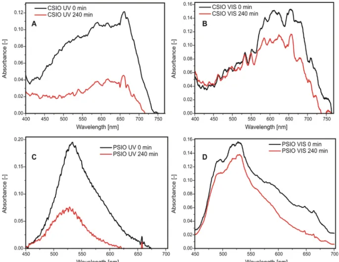
For this reason, methylene blue was dried on the inverse opals, and the decomposition on the surface was followed with UV–Vis reflectance spectroscopy (Fig. 6). While according to the Raman and XRD mea- surements, the samples are identical regarding their composition, the reflectance spectra of the methylene blue differs. In case of all samples, the methylene blue decomposed, even under visible light. This mea- surement was further followed by Raman spectroscopy (Figs. 7 and 8), with similar result as it can be seen inTable 2. In case of the PSIO under visible light irradiation, it showed better performance when in- vestigated with Raman spectroscopy, 58.5% decrease, while with UV–Vis reflectance spectroscopy, it was only 27.5%. This discrepancy may be caused by surface irregularities on the sample. This technique is a more sensitive way to measure the photocatalytic properties of in- verse opals structures, compared to wet photocatalysis in solution. For a non-transparentfilm photocatalyst, e.g. to use in air purification, this can be a more suitable method to evaluate the photocatalytic activity.
4. Conclusions
In this study, we used carbon nanospheres to fabricate inverse opal photonic crystals, which were never used before as templates for this purpose to the best of our knowledge. For reference, inverse opals were made from conventional polystyrene nanospheres. The higher tem- perature tolerance and surface functional groups of the carbon spheres make them more suitable templates for atomic layer deposition than polymer spheres and are easier to remove than silica spheres. Face- centered cubic colloid crystals were prepared from the templates by taking advantage of colloidal self-assembly, and atomic layer deposition was utilized tofill the gaps between the spheres with titania. After annealing and sputtering with argon ions, SEM images revealed the hollow inverse opal structure with interconnected spheres. The bulk material was pure anatase TiO2, as proved by Raman spectroscopy and XRD measurements, and no carbon remained after annealing. UV–Vis diffused reflectance spectroscopy confirmed the presence of the visible photonic band gap. The CSIO had the photonic band gap at a higher wavelength, and was less defined than for the PSIO, because of the larger average diameter and wider size distribution of the carbon spheres. The samples possess photocatalytic activity under UV and visible light in decomposing organic dyes, while bulk TiO2only works under UV light, so this behavior can be attributed to the presence of the photonic band gap due to the inverse opal structure. A new method was developed to test photocatalysis on the surface in case of the methylene blue dye, by utilizing both UV–Vis reflectance and Raman spectroscopy, which can be a better way to evaluate activity for non-transparentfilms, like inverse opals, as it is a more sensitive technique compared to measuring in solution.
Fig. 4.XRD diffractograms of the TiO2inverse opals.
Fig. 5.Diffuse reflectance spectra of the inverse opals.
Declaration of Competing Interest
The authors declare that they have no known competingfinancial interests or personal relationships that could have appeared to influ- ence the work reported in this paper.
Acknowledgments
I. M. Szilágyi thanks for a János Bolyai Research Fellowship of the Hungarian Academy of Sciences. The ÚNKP-18-4-BME-238 New National Excellence Program of the Ministry of Human Capacities, Hungary. A GINOP-2.2.1-15-2017-00084, an NRDI K 124212, an NRDI TNN_16 123631 and an NRDI K 128266 grants are acknowledged. The Fig. 6.Photocatalytic decomposition of methylene blue dried on the samples: on the surface of CSIO under UV (A) and visible (B), on the PSIO under UV (C) and visible (D) light.
Fig. 7.Raman spectra of the methylene blue dried on the surface of the CSIO before after 4 h irradiations.
Fig. 8.Raman spectra of the methylene blue dried on the surface of the PSIO before and after 4 h irradiations.
work performed within project VEKOP-2.3.2-16-2017-00013 was sup- ported by the European Union and the State of Hungary, co-financed by the European Regional Development Fund. The research reported in this paper was supported by the Higher Education Institutional Excellence Program of the Ministry of Human Capacities in the frame of Nanotechnology and Materials Science research area of Budapest University of Technology (BME FIKP-NAT) and the Energetics thematic programme of the University of Debrecen (NKFIH-1150-6/2019). The authors are thankful for Dr. Balázs Réti (Department of Applied and Environmental Chemistry, University of Szeged, Szeged, Hungary) for the carbon nanospheres, Tamás Igricz (Department of Organic Chemistry and Technology, Budapest University of Technology and Economics, Budapest, Hungary) for the Raman measurements and Dr.
Ágnes Szegedi (Green chemistry Research Group, Institute of Materials and Environmental Chemistry, Hungarian Academy of Sciences, Budapest, Hungary) for the UV–Vis diffuse reflectance measurements.
Appendix A. Supplementary material
Supplementary data to this article can be found online athttps://
doi.org/10.1016/j.apsusc.2019.144443.
References
[1] E. Armstrong, C. O’Dwyer, Artificial opal photonic crystals and inverse opal structures–fundamentals and applications from optics to energy storage, J. Mater.
Chem. C 3 (2015) 6109–6143,https://doi.org/10.1039/C5TC01083G.
[2] J.D. Joannopoulos, S.G. Johnson, J.N. Winn, R.D. Meade, Photonic Crystals:
Molding the Flow of Light, Princeton University Press, 2008https://doi.org/10.
1088/1751-8113/44/8/085201.
[3] B. Shao, Z. Yang, Y. Wang, J. Li, J. Yang, J. Qiu, et al., Coupling of Ag nanoparticle with inverse opal photonic crystals as a novel strategy for upconversion emission enhancement of NaYF4: Yb3+, Er3+ nanoparticles, ACS Appl. Mater. Interfaces 7 (2015) 25211–25218,https://doi.org/10.1021/acsami.5b06817.
[4] A. Blanco, E. Chomski, S. Grabtchak, M. Ibisate, S. John, S.W. Leonard, et al., Large- scale synthesis of a silicon photonic crystal with a complete three-dimensional bandgap near 1.5 micrometres, Nature 405 (2000) 437–440,https://doi.org/10.
1038/35013024.
[5] J. Liu, C. Sun, M. Fu, J. Long, D. He, Y. Wang, Enhanced photochemical catalysis of TiO2 inverse opals by modification with ZnO or Fe2O3 using ALD and the hydro- thermal method, Mater. Res. Exp. 5 (2018) 025509,https://doi.org/10.1088/2053- 1591/aaabe9.
[6] J. Xu, B. Yang, Z. Fu, M. Wen, Y. Zhao, Synthesis and photocatalytic property of ZnO/TiO2 inverse opalsfilms with controllable composition and topology, Chinese J. Chem. Phys. 25 (2012) 235–241,https://doi.org/10.1088/1674-0068/25/02/
235-241.
[7] P.V. Braun, P. Wiltzius, Electrochemically grown photonic crystals, Curr. Opin.
Colloid Interface Sci. 7 (2002) 116–123,https://doi.org/10.1016/S1359-0294(02) 00009-2.
[8] B. Hatton, L. Mishchenko, S. Davis, K.H. Sandhage, J. Aizenberg, Assembly of large- area, highly ordered, crack-free inverse opalfilms, Proc. Natl. Acad. Sci. 107 (2010) 10354–10359,https://doi.org/10.1073/pnas.1000954107.
[9] X.Z. Li, F.B. Li, Study of Au/Au 3+ -TiO2 photocatalysts toward visible photo- oxidation for water and wastewater treatment, Environ. Sci. Technol. 35 (2001) 2381–2387,https://doi.org/10.1021/es001752w.
[10] Y. Cao, W. Yang, W. Zhang, G. Liu, P. Yue, Improved photocatalytic activity of Sn4+ doped TiO2 nanoparticulatefilms prepared by plasma-enhanced chemical vapor deposition, New J. Chem. 28 (2004) 218,https://doi.org/10.1039/
b306845e.
[11] R. Asahi, Visible-light photocatalysis in nitrogen-doped titanium oxides, Science (80-.) 293 (2001) 269–271,https://doi.org/10.1126/science.1061051.
[12] N.R. Khalid, A. Majid, M.B. Tahir, N.A. Niaz, S. Khalid, Carbonaceous-TiO2
nanomaterials for photocatalytic degradation of pollutants: a review, Ceram. Int. 43 (2017) 14552–14571,https://doi.org/10.1016/j.ceramint.2017.08.143.
[13] M. Zhang, C. Chen, W. Ma, J. Zhao, Visible-light-induced aerobic oxidation of al- cohols in a coupled photocatalytic system of dye-sensitized TiO2 and TEMPO, Angew. Chemie Int. Ed. 47 (2008) 9730–9733,https://doi.org/10.1002/anie.
200803630.
[14] S.W. Verbruggen, TiO2 photocatalysis for the degradation of pollutants in gas phase: From morphological design to plasmonic enhancement, J. Photochem.
Photobiol. C Photochem. Rev. 24 (2015) 64–82,https://doi.org/10.1016/j.
jphotochemrev.2015.07.001.
[15] T. Jiang, L. Zhang, M. Ji, Q. Wang, Q. Zhao, X. Fu, et al., Carbon nanotubes/TiO2 nanotubes composite photocatalysts for efficient degradation of methyl orange dye, Particuology 11 (2013) 737–742.
[16] I.M. Szilágyi, E. Santala, M. Heikkilä, V. Pore, M. Kemell, T. Nikitin, et al., Photocatalytic properties of WO3/TiO2 core/shell nanofibers prepared by electro- spinning and atomic layer deposition, Chem. Vap. Depos. 19 (2013) 149–155, https://doi.org/10.1002/cvde.201207037.
[17] E. Albert, P.A. Albouy, A. Ayral, P. Basa, G. Csík, N. Nagy, et al., Antibacterial properties of Ag–TiO2 composite sol–gel coatings, RSC Adv. 5 (2015) 59070–59081,https://doi.org/10.1039/C5RA05990A.
[18] J.I.L. Chen, G. Von Freymann, S.Y. Choi, V. Kitaev, G.A. Ozin, Amplified photo- chemistry with slow photons, Adv. Mater. 18 (2006) 1915–1919,https://doi.org/
10.1002/adma.200600588.
[19] J. Liu, H. Zhao, M. Wu, B. Van der Schueren, Y. Li, O. Deparis, et al., Slow photons for photocatalysis and photovoltaics, Adv. Mater. 29 (2017) 1–21,https://doi.org/
10.1002/adma.201605349.
[20] X. Zheng, S. Meng, J. Chen, J. Wang, J. Xian, Y. Shao, et al., Titanium dioxide photonic crystals with enhanced photocatalytic activity: matching photonic band gaps of TiO2 to the absorption peaks of dyes, J. Phys. Chem. C 117 (2013) 21263–21273,https://doi.org/10.1021/jp404519j.
[21] M. Curti, C.B. Mendive, M.A. Grela, D.W. Bahnemann, Stopband tuning of TiO2 inverse opals for slow photon absorption, Mater. Res. Bull. 91 (2017) 155–165, https://doi.org/10.1016/j.materresbull.2017.03.061.
[22] J. Zhang, Z. Sun, B. Yang, Self-assembly of photonic crystals from polymer colloids, Curr. Opin. Colloid Interface Sci. 14 (2009) 103–114,https://doi.org/10.1016/j.
cocis.2008.09.001.
[23] P. Jiang, J.F. Bertone, K.S. Hwang, V.L. Colvin, Single-crystal colloidal multilayers of controlled thickness, Chem. Mater. 11 (1999) 2132–2140,https://doi.org/10.
1021/cm990080+.
[24] Z. Zhou, X.S. Zhao, Flow-controlled vertical deposition method for the fabrication of photonic crystals, Langmuir 20 (2004) 1524–1526,https://doi.org/10.1021/
la035686y.
[25] C. Marichy, N. Pinna, Carbon-nanostructures coated/decorated by atomic layer deposition: growth and applications, Coord. Chem. Rev. 257 (2013) 3232–3253, https://doi.org/10.1016/j.ccr.2013.08.007.
[26] S.M. George, Atomic layer deposition: an overview, Chem. Rev. 110 (2010) 111–131,https://doi.org/10.1021/cr900056b.
[27] I. Alessandri, M. Zucca, M. Ferroni, E. Bontempi, L.E. Depero, Tailoring the pore size and architecture of Ce02/Ti02 core/shell inverse opals by atomic layer de- position, Small 5 (2009) 336–340,https://doi.org/10.1002/smll.200801249.
[28] J.S. King, E. Graugnard, C.J. Summers, TiO2 inverse opals fabricated using low- temperature atomic layer deposition, Adv. Mater. 17 (2005) 1010–1013,https://
doi.org/10.1002/adma.200400648.
[29] Z. Cai, Z. Xiong, X. Lu, J. Teng, Insitu gold-loaded titania photonic crystals with enhanced photocatalytic activity, J. Mater. Chem. A 2 (2014) 545–553,https://doi.
org/10.1039/c3ta13878j.
[30] G.I.N. Waterhouse, M.R. Waterland, Opal and inverse opal photonic crystals: fab- rication and characterization, Polyhedron 26 (2007) 356–368,https://doi.org/10.
1016/j.poly.2006.06.024.
[31] T. Kohoutek, J. Orava, T. Sawada, H. Fudouzi, Inverse opal photonic crystal of chalcogenide glass by solution processing, J. Colloid Interface Sci. 353 (2011) 454–458,https://doi.org/10.1016/j.jcis.2010.10.011.
[32] N. Justh, L.P. Bakos, K. Hernádi, G. Kiss, B. Réti, Z. Erdélyi, et al., Photocatalytic hollow TiO2 and ZnO nanospheres prepared by atomic layer deposition, Sci. Rep. 7 (2017) 4337,https://doi.org/10.1038/s41598-017-04090-0.
[33] J. Tauc, T.A. Scott, The optical properties of solids, Phys. Today. 20 (1967) 105–107,https://doi.org/10.1063/1.3033945.
[34] J. Rieger, The glass transition temperature of polystyrene, J. Therm. Anal. 46 (1996) 965–972,https://doi.org/10.1007/BF01983614.
[35] M.J.Šćepanović, M. Grujić-Brojčin, Z.D. Dohčević-Mitrović, Z.V. Popović, Characterization of anatase TiO2 nanopowder by variable-temperature Raman spectroscopy, Sci. Sinter. 41 (2009) 67–73,https://doi.org/10.2298/SOS0901067S.
[36] L.-L. Tan, W.-J. Ong, S.-P. Chai, A. Mohamed, Reduced graphene oxide-TiO2 na- nocomposite as a promising visible-light-active photocatalyst for the conversion of carbon dioxide, Nanosc. Res. Lett. 8 (2013) 465,https://doi.org/10.1186/1556- 276X-8-465.
[37] R.C. Schroden, M. Al-Daous, C.F. Blanford, A. Stein, Optical properties of inverse opal photonic crystals, Chem. Mater. 14 (2002) 3305–3315,https://doi.org/10.
1021/cm020100z.
[38] J. Zhang, P. Zhou, J. Liu, J. Yu, New understanding of the difference of photo- catalytic activity among anatase, rutile and brookite TiO2, Phys. Chem. Chem.
Phys. 16 (2014) 20382–20386,https://doi.org/10.1039/c4cp02201g.
Table 2
Results of the photocatalytic decomposition of the methylene blue as decrease in peak areas according to UV–Vis reflectance and Raman spectroscopy.
Sample UV–VIS [%] Raman [%]
CSIO UV 70.3 72.7
PSIO UV 69.6 67.6
CSIO VIS 23.6 19.9
PSIO VIS 27.5 58.5