Visual Sense-and-Avoid for Small Size Unmanned Aerial Vehicles
Tamás Zsedrovits
A thesis submitted for the degree of Doctor of Philosophy
Pázmány Péter Catholic University
Faculty of Information Technology and Bionics Multidisciplinary Technical Sciences Doctoral School
Scientific Advisor:
Ákos Zarándy, D.Sc.
Supervisor:
Tamás Roska, D.Sc.
Budapest, 2014
To my lovely wife Kriszti and my sweet daughter Julcsi.
Acknowledgment
First of all I would like to thank and acknowledge the support of my scientific advisor and supervisor Ákos Zarándy. He helped me a lot to find my way at the beginning of the PhD, guided me throughout my work and motivated me with his enthusiasm. I would like to thank also Tamás Roska for his great support and fatherly guidance during my studies.
I am grateful to Péter Szolgay, Judit Nyékyné Gaizler, Ferenc Kovács and Ágnes Bércesné Novák for their continuous support and encouragement during the years.
I am also thankful to my closest collaborators for their help, and for all the discussions we had: Bálint Vanek, Zoltán Nagy, András Kiss, Péter Bauer, Tamás Péni, Borbála Pencz, Máté Németh and Arnold Leitli.
I am very grateful to my colleagues especially to those with whom we shared an office:
Miklós Koller, Gábor Tornai, Mihály Radványi, Tamás Fülöp, Ádám Rák, András Horváth, Attila Stubendek, Domonkos Gergelyi, Csaba Józsa, László Füredi, Kálmán Tornai, Bence Borbély, István Reguly, Csaba Nemes, László Laki, Ádám Balogh, Norbert Sárkány, Zoltán Tuza, János Rudan, Balázs Varga, Dávid Tisza, Tamás Pilissy, Zoltán Kárász, László Kozák, Andrea Kovács, Dániel Szolgay, Ádám Fekete, András Gelencsér, Dóra Bihary, Zsolt Gelencsér, Antal Hiba, Endre László, Borbála Siklósi, András Rácz, Balázs Oláh, Anna Horváth, András Laki, Imre Juhász and Mátyás Jani for their help in any ways.
I am also thankful to our postdoctoral fellows András Oláh, György Cserey, Kristóf Karacs, Kristóf Iván, Zoltán Gáspári and Miklós Gyöngy for their inspiring work and for their encouraging worlds.
I acknowledge also the kind help of the personnel of Students' Office, in particular Katinka Tivadarné Vida, the Dean's Office, the Financial Department and the IT Department. I am also very thankful to Viktória Sifter from the Library.
I am especially grateful to my wife Kriszti who has encouraged me and believed in me all the time. I am very grateful to my mother, my father and my sister and to my whole family who always believed in me and supported me in all possible ways. I am very grateful to my daughter Julia, who let me work close to the deadlines.
Contents
Contents ... i
List of figures ... iv
List of tables ... vii
List of Abbreviations ... viii
Chapter 1 Introduction ... 1
1.1 Preface ... 1
1.1.1 UAS challenges ... 1
1.1.2 UAS integration ... 2
1.1.3 UAS economic effects ... 3
1.2 Aims and motivations ... 3
1.3 Framework of the dissertation ... 5
Chapter 2 UAS Collision Avoidance ... 6
2.1 Collision avoidance ... 6
2.2 Sense and avoid systems... 8
2.2.1 RADAR based SAA ... 9
2.2.2 Bio-motivated SAA ... 12
2.2.3 EO based SAA ... 15
Chapter 3 UAV SAA Test Environment ... 23
3.1 Coordinate Systems ... 24
3.2 Camera model ... 26
3.3 Measured and estimated variables ... 26
3.4 Simulation environment ... 28
3.5 Image processing algorithm ... 30
3.5.1 Detection performance ... 33
3.6 Distant airplane detection ... 35
3.6.1 Pre-processing ... 35
3.6.2 Segmentation ... 36
3.6.3 Tracking... 37
3.6.4 Detection performance ... 38
Chapter 4 Relative Direction Angle Estimation ... 40
4.1 Geometrical description ... 40
4.2 Measurement situations ... 43
4.3 Precision determination ... 44
4.3.1 Pinhole camera ... 44
4.3.2 Points by human expert on simulated images ... 50
4.3.3 Points by automatic algorithm on simulated images ... 53
4.3.4 Points by automatic algorithm on images from real video data ... 53
4.4 Conclusion ... 55
Chapter 5 Error Analysis of Camera Rotation Estimation Algorithms ... 56
5.1 Algorithmic background ... 57
5.1.1 IMU models ... 58
5.1.2 Camera measurements ... 58
5.1.3 Feature extraction and matching ... 58
5.1.4 Homography ... 59
5.1.5 Eight point algorithm ... 59
5.1.6 Five point algorithm ... 60
5.1.7 MLESAC ... 60
5.1.8 Camera rotation and translation from epipolar matrices ... 60
5.1.9 Reconstruction of aircraft attitude change from camera rotation matrix ... 61
5.2 Simulation Methods ... 62
5.2.1 Simulation environment ... 62
5.2.2 Error measures ... 66
5.2.3 Homography algorithm correction ... 66
5.3 Results of the Error Analysis ... 68
5.3.1 Results with absolute feature point precision ... 68
5.3.2 Results with sub pixel precision ... 70
5.3.3 Results with pixelized coordinates ... 71
5.3.4 Results with pixelized coordinates and noise ... 73
5.4 Conclusion ... 73
Chapter 6 Summary of New Scientific Results ... 74
Chapter 7 Applications ... 79
7.1 Mid-size fixed wing UAS ... 79
7.1.1 The aircraft ... 79
7.1.2 Inertial Measurement Unit (IMU) ... 80
7.1.3 Visual sensor-processor system ... 80
7.2 HIL simulation and measurement results ... 82
7.3 Coupled GPS/IMU/Camera attitude estimator implementation ... 83
7.4 Coupled GPS/IMU/Camera attitude estimator ... 84
References ... 89
List of figures
Figure 1.1 World UAV Budget Forecast ... 3
Figure 2.1 The layered concept collision avoidance ... 7
Figure 2.2 Traffic and collision avoidance. ... 8
Figure 2.3 Quadrotor equipped with RADAR sensor ... 10
Figure 2.4 RADAR coverage ... 10
Figure 2.5 Multi-sensor-based fully autonomous non-cooperative collision avoidance system and the system placed to TECNAM P-92 ... 11
Figure 2.6 Concept of collision avoidance based on OF, and the mounted camera system on a fixed-wing UAV ... 13
Figure 2.7 Blimp-based UAV in the test environment and biomimetic image processing system ... 14
Figure 2.8 Fixed –wing MAV with hovering capability and OF based collision avoidance, autonomous hover and transition from cruise to hover ... 14
Figure 2.9 UAV housing artificial ocelli sensor and light polarization based compass ... 15
Figure 2.10 Fixed wing UAVs for data collection, with the planned trajectory and a frame from the recorded video, with the target aircraft ... 18
Figure 2.11 Modified Cessna 172 aircraft and the used camera frame ... 19
Figure 2.12 Test aircraft, the target balloon and a frame from the processed flight video ... 20
Figure 2.13 Quadrotor for the flight tests ... 21
Figure 2.14 Processed video frames (left: real flight, right: simulation) ... 22
Figure 3.1 Flowchart of the closed-loop SAA system ... 23
Figure 3.2 The earth, the body and the camera coordinate systems in general ... 24
Figure 3.3 The earth, the body and the camera coordinate systems in this specific scenario 25 Figure 3.4 Subtended Angle Relative State Estimation (SARSE) methods ... 27
Figure 3.5 Block diagram of the HIL simulator ... 28
Figure 3.6 The HIL simulator ... 28
Figure 3.7 FlightGear rendering test ... 30
Figure 3.8 Input image (2200x1100 pixel) from the simulator ... 31
Figure 3.9 Diagram of the image processing algorithm... 31
Figure 3.10 Result of the first adaptive threshold on a raw 2200x1100 input image ... 32
Figure 3.11 The steps of the segmentation... 32
Figure 3.12 Steps of the image processing... 33
Figure 3.13 Farthest detectable position of the intruder C172p aircraft (wingspan=11m) ... 34
Figure 3.14 Example of the situation with medium contrast clouds ... 34
Figure 3.15 Example of the situation with high contrast clouds ... 34
Figure 3.16 Diagram of the improved image processing algorithm ... 36
Figure 3.17 The steps of the segmentation (ROI size = 24) ... 37
Figure 3.18 Diagram of the tracking algorithm ... 37
Figure 3.19 Distant aircraft trajectory and camera position ... 38
Figure 3.20 Central part of processed video frame with track of intruder ... 39
Figure 4.1 Diagram of the relative direction angle (𝛼) calculation ... 41
Figure 4.2 𝛼 angles calculated from pinhole model and their error to ground truth ... 45
Figure 4.3 𝛼 angles calculated with rounding and their error to original rotation angles ... 46
Figure 4.4 𝛼 angles calculated from pinhole model with rounding ... 47
Figure 4.5 𝛼 angles calculated from pinhole model with rounding ... 48
Figure 4.6 Maximum of absolute value of the errors of the rounded 𝛼 ... 48
Figure 4.7 𝛼 angles calculated from pinhole model with rounding ... 49
Figure 4.8 Maximum of absolute value of the errors of the rounded 𝛼 angles ... 50
Figure 4.9 𝛼 angles calculated from coordinates selected by a human expert on simulated images ... 51
Figure 4.10 Images of wingtip points selected by a human expert and by the algorithm on images generated by FlightGear simulator ... 51
Figure 4.11 𝛼 angles calculated from coordinates calculated by the automatic algorithm simulated on images ... 52
Figure 4.12 One frame from a recorded video; the intruder is shown in the enlarged picture 53 Figure 4.13 𝛼 angles calculated from coordinates calculated by the automatic algorithm on images from real video ... 54
Figure 5.1 Cameras in the EGT frame ... 63
Figure 5.2 Sinusoidal path in the NED frame ... 63
Figure 5.3 Zigzag path in the NED frame ... 64
Figure 5.4 Camera trajectory and feature points in NED frame ... 64
Figure 5.5 Feature points of two consecutive frames on the image plane ... 65
Figure 5.6 Pitch compare for homography on sinusoidal path ... 67
Figure 5.7 Pitch absolute error for homography on sinusoidal path ... 68
Figure 5.8 Compare of the four different algorithm with absolute feature point precision on sinusoidal ... 69
Figure 5.9 Effect of the translation through the sample time change on the pitch angle error ... 70
Figure 5.10 Roll error with subpixel resolution on sinusoidal ... 71
Figure 5.11 The mean error with low resolution on the pitch angle on sinusoidal ... 71
Figure 5.12 Pitch error with pixelization on sinusoidal path ... 72
Figure 5.13 Roll error mean with pixelization on sinusoidal ... 72
Figure 7.1 The aircraft called Orca, the five camera system can be seen on the nose of the fuselage ... 79
Figure 7.2 Block diagram of the integrated inertial and satellite navigation system ... 80
Figure 7.3 The image capturing, processing, and storing system ... 81
Figure 7.4 Solid aluminium camera holder for avoiding cross vibrations ... 82
Figure 7.5 Block diagram of the image processing architecture ... 82
Figure 7.6 The result of the GPS/IMU fusion with respect to the ground truth ... 85
Figure 7.7 The error of the GPS/IMU fusion with respect to the ground truth ... 86
Figure 7.8 The result of the GPS/IMU/Camera fusion with the homography with respect to the ground truth ... 87
Figure 7.9 The Euler angle error of the GPS/IMU/Camera fusion with respect to the ground truth ... 88 Figure 7.10 The yaw error of the GPS/IMU/Camera fusion with respect to the ground truth 88
List of tables
Table 1 Resolution and CPAR of cameras ... 65 Table 2 Yaw error of homography changing with different feature point precision for the
CPAR=0.055°/px camera ... 73 Table 3 Roll error of the four algorithms changing with different feature point precision
for the CPAR=0.093°/px camera ... 78
List of Abbreviations
ACAS Airborne Collision Avoidance System
ATC Air Traffic Control CCD charge-coupled device CEO Chief executive officer CMO Close-Minus-Open
morphological filter
CUDA Compute Unified Device Architecture
CV Collision Volume DCM direction cosine matrix
EASA European Aviation Safety Agency
EKF Extended Kalman Filter ELOS equivalent level of safety EO Electro-optical
EU European Union
FAA Federal Aviation Administration FOV Field of View
FPGA Field Programmable Gate Array GNSS Global Navigation Satellite
System
GPS Global Positioning System
GPU graphical processing unit HIL hardware-in-the-loop HMM hidden Markov model
IEEE Institute of Electrical and Electronics Engineers
IMU Inertial Measurement Unit INS Inertial Navigation System
IR Infra-red
ISO International Organisation for Standardisation
KF Kalman filter MAV Micro Air Vehicle
NAS National Airspace System (USA) NED North-East-Down
NextGen Next Generation Air Transportation System
OF Optical Flow
PC personal computer
RADAR Radio Detection and Ranging RC Radio Controlled
RER relative entropy rate ROI Region of Interest
RPAS Remotely Piloted Aircraft Systems
SAA Sense-and-avoid
SARSE Subtended Angle Relative State Estimation
SSD Solid State Drive SVM support vector machine
TCAS Traffic Collision Avoidance System
UAS Unmanned Aerial System UAV Unmanned Aerial Vehicle USA United States of America USB universal serial bus
Chapter 1
Introduction
1.1 Preface
In the last decade Unmanned Aircraft Systems (UAS) – beforehand Unmanned Aerial Vehicles (UAVs) – technology has evolved considerably. Besides the military applications now there is a great opportunity to use UAS in commercial applications as well [15], [16], [17]. More and more companies start to develop applications and services based on the UAS platform.
According to many aviation experts pilotless aircrafts are going to revolutionize air transport in the near future. As written in the cover story of December 2011 issue of IEEE Spectrum Magazine: “A pilotless airliner is going to come; it's just a question of when,” said James Albaugh, the president and CEO of Boeing Commercial Airlines [18]. Recent examples are from the field of agriculture [19], wildlife and eco conservation [20], search and rescue [21], firefighting [22], delivery of small packages [23], tv broadcasts [24] and even a “Flying Companion” for automobiles [25]. Additionally, there are many great ideas which can improve the quality, reliability or cost effectiveness of a service.
1.1.1 UAS challenges
Nevertheless, in order to use UAS in these fields their reliability needs to be increased as well as their capabilities need to be extended further, their ease of use needs to be improved and their cost have to be decreased. At the same time the regulatory challenge of integrating UAS into national and international air space has to be solved [26]. One of the most important problems which has to be solved is the collision avoidance or sense-and-avoid capability [27], [28]. These functions have to be run on-board even if the connection between the aircraft and the control station is lost or some of the on-board sensors fail.
Furthermore, the absence of standards, regulations and procedures to govern the safe integration of the UAS into civilian air space are against the broader civilian use. The organizations involved in the regulatory process of the air traffic, like Federal Aviation Administration (FAA), or European Aviation Safety Agency (EASA), do not want to decrease the safety of the air traffic systems currently in use. Thus the UAS have to provide an “equivalent level of safety” (ELOS) to manned aircraft while not negatively impacting the existing infrastructure and manned Traffic Alert and Collision Avoidance System (TCAS) [29], [30].
Additionally, privacy concerns have also been raised about the widespread use of UAS by government and business [31].
1.1.2 UAS integration
Currently the routine operation of UAS with a certification for a civilian task at low altitude or in areas where there is little traffic is allowed only in Japan, Australia, South Africa and some other countries. It is important to remark that in regulations UAS means not only the unmanned aircraft but it also refers to the ground station, all the communication devices and services, all the sensors and computers involved and one or more aircrafts too [32].
In the United States FAA has got a roadmap for integration of UAS into the Next Generation Air Transportation System (NextGen), which should be finished no later than 2025, but requires that UAS could operate with no more than one catastrophic failure in a billion flight hours [33].
In the European Union the plan is first to integrate small UAS (less than 150 kg) into the non-segregated airspace no later than 2023 with several line-of-sight conditions (including UAVs connected to the remote pilot station through communication services beyond radio line- of-sight) [34].
In Hungary the preliminary negotiations started last year between the academic, industrial partners and legislators about the necessary steps [35]. Currently the Hungarian regulations cannot distinguish between the RC planes used by hobbyists and the commercial UAS [36]. Both can be used outside of populated areas in visual line-of-sight range without any special permission and they can be used elsewhere with the permission of the local authorities.
The Hungarian regulations will be harmonised with the EU regulations later on.
1.1.3 UAS economic effects
According to the forecasts, the research and development expenditures on UAS are growing in the next decade [37]. Although the main driving force are still the military agencies, the development and manufacture of UAS for use by public entities (i.e., federal, state, or local governments, and by public universities) and commercial users are expected to grow over the next few years [38]. Unfortunately, numerous regulatory and technical issues remain to be resolved before government agencies or commercial operators can begin routine flight operations in the national airspace.
Figure 1.1 World UAV Budget Forecast [39]
1.2 Aims and motivations
As stated in the roadmap for remotely piloted aircraft systems (RPAS) in the EU, first the small aircrafts will be integrated [34]. Provided that the size and the energy consumption of the UAV are limited, a camera based avoidance system would provide cost and weight advantages against the systems currently in use on bigger aircrafts, like cooperative systems for example TCAS [29]. Furthermore near airfields, because of a great density of aircrafts and the limited frequency resources of air traffic controllers the camera-based approach seems to be more feasible then others.
Although the camera based solutions has limitations on weather conditions in which they can be used as well, at this first stage of research these are less important than the size and power limitations. Furthermore most of the weather limitations can be handled with
supplementary infra-red sensors in the near future, as these sensors are cheaper and cheaper and their resolution is developed a lot in the last decade. Thus the goal was that the developed algorithms work fully in good weather conditions, when the sky is blue or when there are low or medium contrast clouds. These methods work partially, when there are high contrast clouds, which means some additional data on the actual scene is needed.
Today’s kilo-processor chips allow us to implement complex algorithms in real time with low power consumption, so even if we use more sophisticated algorithms for the collision avoidance task, it has a smaller impact on the maximum flight time of the system than the special manoeuvre we have to run in some cases for the position and path estimation of the other aircraft, we want to avoid.
My work was done in a research group funded by the Office of Naval Research (ONR) and ONR Global within the framework of the grant N62909-10-1-7081. The main goal of this research is to develop an autonomous mid-size fixed-wing safety critical UAV for civil applications. The development of the actual hardware went parallel with the development of the algorithmic framework which included the research on vision based UAVs. At the time of this research there were no complete, visual SAA system for mid-size and small UAS and the properties of this kind of systems had been not described yet.
The aim of this work is to introduce and analyse visual methods for the UAS SAA problem. In particular, what kind of information can be extracted from the image flow if the intruder airplane is close enough that is its shape and position can be calculated? This information will be used in the position and path estimation of an aircraft which can be seen on our camera. We want to avoid the run of a special extracting manoeuvre which is used during the estimation, but consumes a significant amount of fuel. On the other hand we wanted to know what can we expect from various visual space reconstruction algorithms in the case of own aircraft’s attitude estimation. This is important because the positions and paths of another aircraft are estimated relative to our camera. The more accurate our own attitude estimation, the better and quicker our estimation process.
In [1]-[14] a camera-based autonomous on-board collision avoidance system and its implementation aspects on kilo-processor architectures are introduced which is the main framework and application of the results are shown in this thesis.
1.3 Framework of the dissertation
The organization of the dissertation is as follows. In Chapter 2 the concept and recent developments of the collision avoidance systems for UAS are introduced giving special importance to sense and avoid (SAA) systems. Although these systems are comparable with the results of the whole research project which include the results of this dissertation, this introduction gives a broader perspective in which my work can be put. In Chapter 3 the base ideas and the most important principles are shown which are used in the development of the UAV SAA system, including the used simulation environment and an image processing algorithms for the aircraft detection. This system was the result of the joint work of our research group and formed the basis of my research. In Chapter 4 the relative direction angle estimation algorithm is introduced and the capabilities of the algorithm are shown, which are summarized in the first thesis group in Chapter 6, as this new algorithm is one of the scientific results of my work In Chapter 5 four camera pose estimation algorithms are investigated in simulations. The aim of the investigation is to show the strengths and weaknesses of these algorithms in the aircraft attitude estimation task. The results are summarized in the second thesis group in Chapter 6. Thus Chapter 6 summarizes the new scientific results in this dissertation. Finally, in Chapter 7 the developed UAV platform as the main application target of the results is shown.
Chapter 2
UAS Collision Avoidance
In this chapter the concept and recent developments of the collision avoidance systems for UAS are introduced giving special importance to sense and avoid (SAA) systems. The collision avoidance capability is one of the most important features that UAS must have before they are let in the common airspace, for example the National Airspace System (NAS) in the USA. This task has to be run autonomously and on board even if the connection between the aircraft and the base station is lost.
2.1 Collision avoidance
In air traffic management the rules of the safe flight operations are given. In order to reduce the risk of mid-air collisions and prevent accidents caused by wake turbulence, aircrafts have to keep a separation distance (separation minima) from another aircrafts [40]. This separation is well defined in the regulations and maintained by the air traffic controllers (ATC).
The given rules take into account different types of aircrafts, different types of safety equipment, as well as different scenarios.
Besides the traffic management rules, there are airborne collision avoidance systems (ACAS). The objective of ACAS is to provide a backup collision avoidance system for the existing conventional air traffic control system without the need of any ground services and to minimize the false alarms, in encounters for which the collision risk does not warrant escape manoeuvres [41]. These methods are considered as cooperative collision avoidance, because the ACAS of the aircrafts, which are participating in the scenario are communicating with each other.
However, in general only bigger and most expensive aircrafts are equipped with ACAS.
On smaller and cheaper aircrafts for the collision avoidance mainly the pilot is in charge.
Most of the time, the safe operation is possible this way as well, because the operation altitude and the maximum speed of these smaller aircrafts is much smaller than the bigger aircrafts. If the two aircrafts are not communicating with each other, the aircrafts have to run non- cooperative collision avoidance. In the case of a human pilot the concept called see and avoid, as in the case of a UAS it called sense and avoid. The different kind of collision avoidance systems form a layered approach, which can be seen in Figure 2.1.
Figure 2.1 The layered concept collision avoidance
In Figure 2.1. the scenario is shown where a manned and an unmanned aircraft come close to each other. The manned aircraft called intruder as it is crossing the path of the UAS. As a typical situation, the manned aircraft is in cruise mode that is a straight path can be assumed.
The intruder first has to be detected in some way, and after that its path has to be estimated. To be able to avoid the separation minima, the intruder should be detected from a distance, which is not smaller than the traffic avoidance threshold. If the intruder is not detected before crossing the traffic avoidance threshold, but detected before the collision avoidance threshold, the collision can be still avoided. Because of the small size of the UAV, we can assume that the pilot of the intruder cannot see our aircraft early enough to run an appropriate avoiding manoeuvre.
For human pilots the minimum reaction time from the first time they discovered an object is 12.5 seconds including the recognition of the object, the recognition of the collision risk, the decision, the muscular reaction and the aircraft lag. It means that for a human pilot 12.5 before collision is the last time instant, when collision can be avoided [42]. Naturally, to avoid scaring the pilots and the passengers of the other aircraft, and to increase the safety level, earlier initialization of the avoidance manoeuvre is required, which certainly assumes earlier detection.
It would be better to give the separation minima for a given aircraft category as a requirement for the UAVs, but this is out of the scope of this thesis. Most of the time UAV systems have smaller lag times and are capable of running manoeuvres with higher accelerations, as there is no human pilot on-board.
Figure 2.2 Traffic and collision avoidance.
As an example a small or medium size UAS is presented. Since the tracks of the small and medium size UAS usually do not interfere with streamliners, or high speed jets, they have to be prepared for other UAS and small sized manned aircrafts, like the Cessna 172.
This means that the expected maximal joint approaching speed is 100 m/s, therefore they should be detected from 2000 meters (20 seconds before collision), to be able to safely avoid them.
2.2 Sense and avoid systems
In the literature there are many approaches to address the SAA problem. The SAA systems are at different levels and the method of solving the problem differs a lot as well. There are partial solutions, which address some aspects of the whole SAA task, like detection, segmentation, tracking or the detection and control. Each of these methods varies with the type (fixed, rotary or flapping wing) and the size of the UAV, as well as with the available sensors and the environment in which the application is run. In [43] several sensor technologies were examined to determine which on can be a good candidate for the main sensor of a UAV SAA system. The tested sensors are: Visual/Pixel, Infrared, Microwave RADAR, LASER RADAR and Bistatic RADAR. Although the visual sensor had the best score among them, the LASER and the Microwave RADAR had similar performance.
intruder collision volume (CV) separation minima (SM)
collision avoidance threshold
traffic avoidance threshold
UAS tracks
In the next subsections examples from the literature are shown also with remarks upon the strengths and weaknesses of the particular solution. In 2.2.1 the RADAR based solutions are introduced, and in 2.2.2 the related papers from the bio-motivated SAA are shown, and finally in 2.2.3 the EO based solutions are presented.
2.2.1 RADAR based SAA
In [44] the concept of a RADAR based collision avoidance system for smart UAS is introduced. The main idea of the cooperative and non-cooperative collision avoidance is shown with the current collision avoidance systems for manned aircrafts. The requirements for this system are different from the requirements of our system as the UAV, which is used here is capable of flying with 440 km/h (~122 m/s) and the SAA system can be 25 Kg while in our case the expected joint speed of the intruder and our UAV is 100 m/s (the speed of our UAV is around 40 m/s) and the size of the whole control system is less than 1 kg. The authors show the desirable small-sized and light-weighted RADAR design and the capabilities. This paper shows the feasibility of the solution as the performance meet the ELOS criteria.
The performance of the system is calculated considering the sensor detection ranges and speed and the mean reaction time of a pilot. The work is continued in [45] with simulation of typical scenarios. Simulations show that the probability of the detection is 90% at the given detection range and that the probability of the collision avoidance is more than 85% in the presence of error. The main advantage of this system that it is scalable according to the requirements and the detected objects range information is available. Furthermore, the distance from the intruder can be detected is bigger compared to the EO sensor based systems. Also these systems can be used all time and all weather conditions. The main drawbacks are the size, weight, power consumption and relatively slow data rate (2 Hz).
More recently in [46] and [47] a miniature RADAR system is introduced for miniature unmanned air vehicles (MAV). The system design and concepts are shown in [46]. The system is lightweight (only 230g) and is capable of detecting and identifying aircrafts of many type and size, which meet with our requirements. This first paper shows an indoor test for the system, where the RADAR is put on board of a small rotorcraft and the MAV is fixed to the ground. In this indoor test a conventional type miniature helicopter is detected and identified from 3m. The identification is done by comparing the detected Doppler pattern to a signature database through Sum of Absolute Differences (SAD). The SAD can provide real-time identification, because it is easy to compute. The signature vector is based on the frequencies generated by the target
aircraft’s propulsion system. In the paper 3 target vehicles are identified. The main problem with this is that if the database contains more vehicles a more complex algorithm is needed, which has negative effect on the real-time capability of the system. Another drawback is that the RADAR beam should be focused in order to have this high resolution, so it cannot cover the entire area needed for the detection.
Figure 2.3 Quadrotor equipped with RADAR sensor
Figure 2.4 RADAR coverage
In [47] the results of outdoor tests are shown. First the indoor tests were repeated in outdoor environment that is the two vehicles stayed on the ground 7m from each other but the engines were operating. In this case the detection rate is 100% as before. This prove the authors hypothesis that the random frequencies produced by the environment does not disturb the measurement significantly. In the final test both vehicles were airborne. In this case the accuracy is dropped significantly due to the fact that it is very difficult to keep the two vehicles in the right position, which shows again that the focused RADAR beam is covers a relatively small area.
Another concept is shown in [48]-[51] where the system uses information from RADAR as well as from EO sensor. This way the all-time, all-weather conditions operation can be provided because of the RADAR as well as the desired angular resolution because of the image sensor. The main sensor is a Ka-band pulsed RADAR and the aiding sensors are IR and conventional EO cameras.
In [48] the system architecture for collision avoidance is shown. This system consists of 2 IR and 2 regular EO cameras and a RADAR next to the conventional guidance navigation and control (GNC) system. The paper focuses on the tracker algorithm for the collision avoidance task. It is stated that it is not the accuracy what is important but the reliability of the tracker at short distances, because at long distances the probability of the collision scenario is lower. Different type of Kalman filters (KF) are tested in numerical Monte Carlo simulations, and the Extended Kalman Filter (EKF) based solution is selected as the best compromise between reliability, computational load and accuracy.
In [49] and [50] a multi-sensor-based fully autonomous non-cooperative collision avoidance system for UAS is introduced. This system is developed for a High-Altitude Long-Endurance (HALE) UAV. The size and weight is comparable to a lightweight commercial aircraft. The system is tested on a TECNAM
P-92 with wingspan of 8.7m and weight of 450Kg. For the detection Optical flow (OF) and feature point matching was tested. Because of the resolution limitations and the computational cost of the OF,
the feature point matching was selected.
Figure 2.5 Multi-sensor-based fully autonomous non-cooperative collision avoidance system and the system placed to TECNAM P-92
For the sensor fusion a central-level fusion architecture was selected with decentralized detection. It means that the detection is performed on each sensor separately to avoid the high
communicational burden caused by raw data exchange, but the object tracking is run in a unique central-level tracking module. For the tracking an EKF is used with Cartesian coordinates.
The concept was tested in numerical simulations and the performance met the requirements.
The system was built and it was calibrated. Also preliminary flight tests were performed, where they recorded different scenarios for offline processing.
Finally in [51] flight tests for the RADAR component of the developed system was run.
The performance of the tracker was measured by accuracy of the estimated the closest point of approach (CPA). This study showed that the used RADAR is capable of detecting the intruder aircraft reliably. The ranges were compared with GPS measurements. It was shown that on low altitudes there is a significant noise due to the clutter from the ground. This system provided reliable situational awareness at 10 Hz.
It is stated that the detection unit needs a decent navigational unit as the performance of the detection is depends on the accuracy of the navigation, which coincide what we have seen during our work and also confirms that the controls system can benefit from additional visual information. The authors mention that the angular velocity biases did not cause any problem in this case, because the misalignment of the RADAR sensor to the aircraft’s body axis did not change with time. On the other hand it is a real problem for the fused system, because the different sensors will have different biases.
The main advantage of this system is that it is capable of running the SAA in all-time all-weather conditions. Due to the camera sensor it is more reliable and more accurate than other RADAR systems. The main drawback of the system is the problem caused by the fusion of different sensors. The system cannot be cheap because of the used sensors, and it is heavy as well, so it cannot be used on a mid-size or small UAV. The computational costs are high as well because of the image processing and the sensor fusion. Furthermore, as it is stated in the last paper, the biases caused by the navigation measurements have significant effect on the performance of the system.
2.2.2 Bio-motivated SAA
The bio-motivated systems focus more on the control and attitude estimation of the UAS. These results can be a good starting point towards a complete SAA system. The main advantages of the bio-motivated systems will be the low power consumption, the small size and the robustness. The main downside can be that the integration of these components into conventional systems is not straightforward. In the following four examples are shown.
In [52] a biomimetic visual sensing and control system for MAVs are introduced. In the paper two models are introduced for visual navigation in insects: an optic flow based approach, when the insect uses its compound eye for depth and range sensing and collision avoidance, and another visual sensing based on the ocelli organ for flight stabilization. In the paper it is shown how insects use these sensing information in different tasks, for example for landing or hovering.
The available OF sensor chips and artificial ocelli sensor is introduced with the control algorithms. At the time the system was capable of flying at low altitudes (some meters) and following a shallow (±10°) terrain. The development of the system is still in progress. This system is designed for micro air vehicles and for flapping-wing, insect-like robots, which typically fly at low altitudes. The main advantage of the system is that it will be cheap and extremely lightweight. The main drawback is that because of the OF algorithm it cannot be scaled up for a bigger UAS and that it needs special hardware elements (OF chip).
Figure 2.6 Concept of collision avoidance based on OF, and the mounted camera system on a fixed- wing UAV
A biomimetic flight control system for blimp-based UAS is shown in [53]. The system consists of two forward looking CCD cameras with wide angle optics, providing 180° horizontal field of view (FOV). The recorded images are processed at the ground control station. The stabilization and collision avoidance are derived from insect neuronal models. The image processing uses the photoreceptor’s logarithmic rule and the centre-surround antagonism in order to introduce robustness in the system and reduce redundancy. After that two independent processing streams are run parallel to calculate stabilization and collision cues and at the control the collision sues have preference. This system can be used indoor environments and with slowly moving vehicles (blimp) only. In the tests the some black and white patterns were used in order to enhance the contrast, because it needs objects with enough contrast for the robust operation which is another drawback.
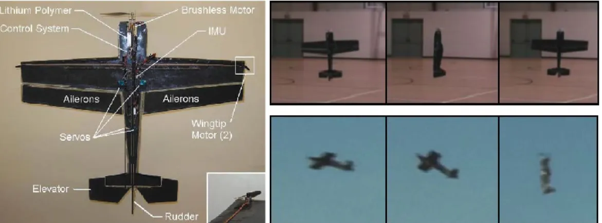
Figure 2.7 Blimp-based UAV in the test environment and biomimetic image processing system In [54] again an optic flow based lateral collision avoidance is used on a MAV. This MAV is a fixed-wing aircraft, but with hovering capabilities, so it is well suited for low altitude flights and applications like homeland security applications, or search and rescue. The authors uses again models found investigating flying insects. The main problem with the solely optic flow based collision avoidance was that it performs badly when the vehicle was flying directly at low textured obstacles, for example walls. The hovering mode is the authors answer for this problem. The hovering allows the MAV to avoid imminent collisions and also to manoeuvre through tight spaces.
Figure 2.8 Fixed –wing MAV with hovering capability and OF based collision avoidance, autonomous hover and transition from cruise to hover
Besides the concepts and models the developed MAV is also introduced. It has got 1m wingspan, 600g weight and a speed range from 0 to 20 m/s. For the hovering mode roll stabilization additional wingtip motors are installed. The MAV uses an IMU outputting direction quaternions with 100 Hz. It is capable of autonomously hover and autonomously switch between cruise and hover. The authors hope that with an additional proximity sensor (for example
ultrasonic distance sensor) installed on the nose the aircraft can automatically switch from cruise to hover when it flies to a wall. The main advantage of this system that it can cruise and hover as well. Although the collision avoidance algorithm is not suited for higher altitude flights than a couple of meters. Another drawback is that additional motors are needed on the wingtips for the hover mode.
The next paper shows the development of biomimetic attitude and orientation sensors [55]. The orientation sensor is based on the polarization of light changes caused by Rayleigh scattering. The polarization is measured by three cameras each of them with different polarization filter. This mimics the function of the dorsal rim area of dragonflies. The developed device was calibrated and tested in static and flight tests. The accuracy of the device is comparable to the accuracy of a conventional magnetic compass sensor. The attitude sensor is based on the ocelli. The function of the ocelli is flight stabilization that is the precise control of the roll and pitch angles. The artificial ocelli consists of four pairs of miniature cameras. Each pair has got a green and an ultra-violet sensor. The tests showed that the roll angle can be controlled by this sensor but the pitch angle was inconsistent. The roll angle error during flight test was less than 2°.
Figure 2.9 UAV housing artificial ocelli sensor and light polarization based compass
2.2.3 EO based SAA
The main advantages of the EO based SAA systems are that they are lightweight and have affordable price. The drawbacks are the relatively high computational cost of the processing algorithms and the restricted weather conditions and range. As the examples show, despite the drawbacks these systems can be a good choice for small UAS.
In [56] the available algorithms and ideas in 2004 are reviewed and a new SAA algorithm is introduced. According to the authors the RADAR sensors were not feasible for the task because of their size and power consumption as well as LASER. SONAR sensors have only a few meter detection range and suffer from multipath propagation and other noise causing effects. They found monocular camera systems as a good candidate for UAS applications.
Authors reviewed the state-of-the art image processing algorithms as well. Because of the large depth of field requirements and the fast attitude changes OF algorithm is not good for the purpose. They found feature tracking methods not feasible, because of the fast attitude changes and high computational need and focus of expansion algorithms are not suitable as well, because of the same reasons.
The authors propose a new algorithm, which uses feature density and distribution analysis. The algorithm uses edge and corner features and calculates the time-to-impact based on the expansion rate of feature density and distribution. According to the tests the algorithm is robust to low image quality. On the other hand the algorithm was sensitive to the aircraft’s attitude changes. Furthermore the target had to be sufficiently large (bigger than 40% of the image), in order to get good expansion rate, and only one target could be tracked at a time.
In the papers [57]-[63], the development of a computer vision based collision avoidance system is shown. This system is developed at the Queensland University of Technology, Australia, as a part of the Australian Research Centre for Aerospace Automation’s Smart Skies research project. The main advantage of this research project is that they have access to various types of aircrafts, sensors and computational resources, and have a big database of flight videos collected in various situations.
In [57] the feasibility study of the vision based collision avoidance system is presented.
The system uses a monocular camera as the main sensor for the detection. In this first stage the camera had a 1024x768 resolution and a 17°x13° FOV. For the detection a Close-Minus-Open (CMO) morphological filter is used. This approach finds both bright and dark objects on grayscale images using the grayscale version of the close and the open filter. The output of the CMO still contains significant amount of false targets due to image noise. In order to filter out most of the false targets a dynamic programming algorithm is used.
The algorithm was tested on image sequence contains a distant aircraft and heavy cloud clutter in the background. The results showed that the method is feasible for the collision avoidance. Problems caused by moving platform are not addressed in this stage, but the authors propose of the use of the inertial sensor measurements for supressing the effect of the camera motion later.
In [58] the CMO based algorithm is compared with another morphological filter, the so called Preserved-Sign (PS) filtering. The PS is very similar to the CMO except it preserves the sign of the features, and this way the image noise can be characterised with a zero mean
Gaussian function, which improves the performance of the subsequent noise filtering. In the paper the performance of the CMO approach is compared to a human observer.
It is shown that the algorithm performed better than the human observer even in the cloudy situation. The consistent target detection of the algorithm was 19% further than the human detection distance. The test of the two different filtering approach showed that the PS performs slightly better, but the additional computational cost is too high. The ego motion compensation is still mentioned as a problem for the future development.
In [59] a new hidden Markov model (HMM) temporal filtering for the detection is introduced with the addition of relative bearing and elevation estimation capabilities.
Additionally, the algorithm is implemented on graphical processing unit (GPU) and a benchmark on different GPUs is shown. Furthermore, a control strategy for collision avoidance based on target dynamics and estimation of target relative bearing/elevation angles is described.
For the HMM two complementary hypotheses are considered, the first one is, when there is one target and the second, when there is no target on the image plane. They used four independent HMM filters on the same preprocessed image, which means after the CMO filtering step. The dynamics of the target is extracted using a standard projective model, using pinhole camera. They developed a new control law for the collision avoidance task as well based on the calculated relative angles and the camera motion model (the optical flow equation). This new control law was under testing at that time.
The performance of the different GPU architectures are introduced in this paper as well.
The implementation used the CUDA C language and the GTX280, the 8800GTS and the 9600GT chips from nVIDIA were running it. The computation speed was compared to a naïve C implementation on a Pentium IV based PC running Linux. The improvement was x20, x7 and x1,5 respectively. For the final implementation the 9600GT was used, because its power consumption is the smallest from these three GPUs, it is 59 W. It was capable of doing the computation with 11Hz. After further code optimizations the authors expected 30Hz image processing rate with the 9600GT.
In the next paper [60] besides the HMM, a Viterbi-based filtering method is evaluated in realistic situations. The test videos are recorded using two UAVs simulating a collision situation. In the tests the Viterbi-based filtering had a slightly bigger detection range, but the SNR for the HMM was much better. The computational cost of the two algorithms is very similar.
The authors built a GPU based system for the detection, and according to the paper it is suitable for UAV integration. The power consumption of the GPU itself is 59W and there is a host computer next to it, which seems to be too much for a small size UAS.
Figure 2.10 Fixed wing UAVs for data collection, with the planned trajectory and a frame from the recorded video, with the target aircraft
Due to the fixed-wing aircraft platform and the autonomous flight mode for the UAVs they had difficulties during the data collection. That is why they decided to switch to a manned, full sized airframe (Cessna 172) to collect a big database of video data. This data is used to further test the algorithms.
In [61] the authors propose a visual-spectrum image-based method of obtaining supplementary bearing angle rate information that exploits CMO preprocessing, HMM temporal filtering, and relative entropy rate (RER) concepts. The main contribution of this paper is the proposal of an online vision-based heading angle and speed estimator for airborne targets using these concepts. In particular targets that appear as small features in the image measurements without distinct texture or shape are considered. A possible connection between RER and probabilistic distance measures are considered first. Then a mean heading angle and speed estimator (or pseudobearing rate estimator) that exploits this connection is proposed.
The tests for this algorithm are run on computer-generated image data, real ground- based image data, and real air-to-air image data. The simulation studies demonstrated the superiority of the proposed RER-based velocity estimation methods over track-before-heading- estimation approaches, and the study involving real air-to-air data demonstrated application in a real airborne environment.
In [62] and [63] the extensive experimental evaluation of the sky-region, image-based, aircraft collision-detection system introduced in the previous publications is shown, with the description of a novel collection methodology for collecting realistic airborne collision-course target footage in both head-on and tail-chase engagement geometries. Under blue sky conditions, the system achieved detection ranges greater than 1540m in three flight test cases
with no false-alarm events in 14.14 h of non-target data (under cloudy conditions, the system achieved detection ranges greater than 1170 m in four flight test cases with no false-alarm events in 6.63 h of non-target data).
The new methodology for flight video collection is remarkable as well. In all flight experiments, the camera aircraft was a custom modified Cessna 172 and the target aircraft was a Cessna 182. In order to avoid dangerous situations and to provide reliable data, they followed ISO standards for the data collection experiments. This way they could test the algorithms on the basis of a uniquely large quantity of airborne image data. The image data was analised before the test based on the target range, the SNR and the cloudiness.
Figure 2.11 Modified Cessna 172 aircraft and the used camera frame
On the test data the detection range versus the false-alarm rate is calculated with both the Viterbi and the HMM algorithm. These curves are treated as system operating characteristics (SOC), even if the dataset is still small for a proper statistical analysis. The empirically determined SOC curves were able to demonstrate that morphological–Viterbi-based approaches seem very unlikely to be a practical solution to this collision detection problem (due to high false-alarm rates). Conversely, a morphological–HMM-based approach was shown to be able to achieve reasonable detection ranges at very low false-alarm rates (in both blue sky and cloudy conditions).
It seems that these methods are well thought out and extensively tested in real situations.
The detection range and false alarm rates are very impressive, and the authors have the biggest known airborne video database as well, with a real target aircraft. The main drawback seems to be the power consumption of the proposed system due to the computationally extensive preprocessing and temporal filtering steps. The algorithm is capable of detecting aircrafts in the sky region and only the videos with dark targets are involved in the tests.
In [64] an obstacle detection method for small autonomous UAV using sky segmentation is introduced. The proposed algorithm uses a support vector machine (SVM) on
YCrCb color space to separate sky and non-sky pixels. The recorded images are first filtered with a Gaussian filter, and then segmented with the SVM. The horizon is determined according to the sky and non-sky pixels using Hough transformation. The objects are formed of those non- sky pixels which are in the sky region. The algorithm is real-time and was tested in hardware- in-the-loop (HIL) simulations, as well as in real flight tests. The main disadvantage of the algorithm is that it can only detect obstacles above the horizon that are viewed with sky in the background. In our system besides the detection on the sky region, the detection below the horizon will be included as well.
Figure 2.12 Test aircraft, the target balloon and a frame from the processed flight video
In [65] and [66] the development of a SAA system is shown. According to the paper the system has the potential to meet the FAA’s requirements. This system uses 3 CCD cameras as sensors and FPGAs for the processing. Detection and tracking algorithms characterize global scene motion, Sense objects moving with respect to the scene, and classify the objects as threats or non-threats. Detection algorithms operate directly on sensor video to extract candidate features. Tracking algorithms operate on the candidate features (“detections”) to correlate them over time forming “tracks.’ Declaration algorithms operate the track set to classify them as threat or non-threat based on their temporal behaviour.
A total of 27 collision scenario flights were conducted and analysed. The average detection range was 11.6 km and the mean declaration range was 8 km. There were many false tracks first due to the sensor vibration, but later on an improved sensor mount was developed which helped to lower the false alarm rate significantly. The number of false alarms per engagement has been reduced to approximately 3 per engagement. This shows the importance of a good anti-vibration system. In our approach, as we are using a five camera system we had to handle the cross vibration of the cameras as well. Unfortunately, because this system was developed for US Air Force, the details are not provided for the algorithms or the system.
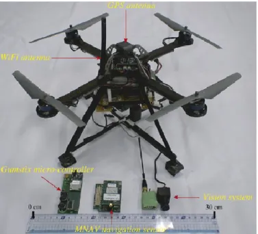
In [67] and [68] a system with 3 nested KF for OF computation, UAV motion estimation and obstacle detection is introduced. The system is used as a vision based autopilot for small
UAVs, flying close to the ground, in cluttered, urban environment. They use a monocular camera as the main sensor. The three KF are exchanging information about the UAV’s motion and the estimated structure of the scene.
The OF calculation is using block matching and differential method. The block matching uses motion constraints based on the INS module, and uses an adaptive shape for the matching. The rough estimates given by the block matching are then refined by the differential algorithm. The results are filtered with the first KF in order to select features for the structure computation and to determine the angular velocity. For the ego motion estimation, the results from this module and the measurements from the INS are fused with the second KF. And the third KF is used to estimate the pure translational motion of the UAV.
Figure 2.13 Quadrotor for the flight tests
The algorithm is tested in numerical simulations and in real environment. A quadrotor is used with a low cost IMU and a downward looking camera with 320x240 px resolution
@25Hz. The quadrotor has a 400g weight and can carry a 300g payload. The scale ambiguity introduced by the camera is resolved with a static pressure sensor. The efficiency and robustness of the proposed vision system were demonstrated for indoor and outdoor flights. The problem with this approach is that the computations are run on a ground control station, and the obstacle detection was not tested. In this way the UAV is not capable of doing the collision avoidance if there is a lost connection in between the aircraft and the base station. In our system all processing is done on-board.
In [69], [70] and [71] introduces a visual collision and detection system based on a monocular camera. A new method called expansion segmentation is shown, which simultaneously detects “collision danger regions” of significant positive divergence in inertial aided video, and estimates maximum likelihood time to collision (TTC) within the danger regions. The algorithm was tested in simulations and a real video as well. The algorithm was implemented in C and was run on a Core 2 Duo PC @0.2 Hz. The main drawback of this concept is that the size of the intruder has to be big enough in order to determine the expansion rate. It means that the range of the detection is small or the camera sensor has to have a very big resolution.
Figure 2.14 Processed video frames (left: real flight, right: simulation)
Chapter 3
UAV SAA Test Environment
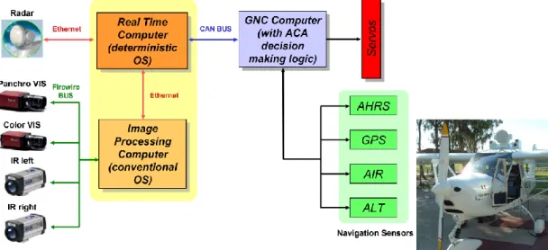
In this chapter the base ideas and the most important principles are shown which are used in the development of the UAV SAA system. In order to develop and test new methods and algorithms for UAS SAA, a test environment was built. This setup consists of three main parts, the sensors, the image processing part and the control part.
The goal of our research is to create a complete, autonomous flight control system for UAS. This is a closed loop flight control system with the collision avoidance capability based on visual detection of the approaching object (Figure 3.1). The organization of the system is as follows.
The first part contains the sensors. The input images are recorded by the Camera and the own position and inertial data measured by the on-board INS/GPS (Inertial Navigation System/Global Positioning System).
Image
Acquisition Preprocessing Detection Data Association
& Tracking
Camera INS/GPS
Flight Control
Trajectory generation
Collision Risk Estimation &
Decision
Motion Prediction Sensors
Image Processing
Control
Figure 3.1 Flowchart of the closed-loop SAA system
The second part is the image processing. The recorded pictures are transmitted by the Image Acquisition to the Pre-processing block by which the pictures are filtered.
The next step of the processing is the Detection. The images are processed by image processing algorithms to detect the approaching objects. The Data Association & Tracking is responsible for the combination of the orientation and angle of attack data of the approaching object calculated by the Detection.
The third part is the flight control. According to the combined data the relative motion of the approaching object is predicted by Motion Prediction. If a risky situation is identified by Collision Risk Estimation & Decision a modified trajectory is generated by the Trajectory generation. The avoiding manoeuvre is passed to the Flight Control, which is responsible for the autonomous control of the aircraft.
3.1 Coordinate Systems
In most applications a small UAV flies only short distances (about several kms of range). This allows considering the North-East-Down (NED) frame as an inertial (non-moving, non-rotating) frame (earth frame) [32]. The NED frame is defined as follows: the Z axis is the normal vector of the tangent plane of Earth at aircraft starting position pointing into the inner part of the ellipsoid. The X axis points to north and the Y axis forms a right-handed system with the other two. The NED is referenced later on as the earth coordinate system as well.
Figure 3.2 The earth, the body and the camera coordinate systems in general . (Xearth, Yearth, Zearth) earth (NED), (Xbod𝑦, Ybody, Zbody) body
and (Xcam, Ycam, Zcam) camera coordinate systems.
𝑒𝑏̅̅̅ the position of aircraft centre of gravity in earth coordinate system, 𝑏𝑐̅̅̅ the position of camera in body coordinate system and 𝑥̅ the position of a feature point (X) in earth coordinate system
The other two applied coordinate systems are the body and camera systems. The body frame is fixed to the aircraft centre of gravity with Z axis pointing downward, X axis pointing forward and the Y axis forms a right-handed system with the other two.
The axes of the camera system are in general nonparallel with the axes of the body system (see Figure 3.2). In the considered set up the axes of the camera and body coordinate systems are parallel but the camera coordinate system is rotated in the body frame (Figure 3.3).
In Figure 3.2 X is a feature point in the earth coordinate system characterized by vector 𝒙
̅earth (the ( )̅̅̅earth means a vector with coordinates in earth coordinate system). 𝒆𝒃̅̅̅̅earth gives the position of the body frame relative to earth while 𝒃𝒄̅̅̅̅body gives the position of the camera frame relative to body. The coordinates of point X in the camera frame can be calculated as follows:
𝒙 ̅
cam= 𝐂𝐁 ̿̿̿̿ 𝐁𝐄 ̿̿̿̿ (𝒙̅
earth− 𝒆𝒃 ̅̅̅̅
earth− 𝒃𝒄 ̅̅̅̅
earth) =
= 𝐂𝐁 ̿̿̿̿ 𝐁𝐄 ̿̿̿̿ (𝒙̅
earth− 𝒆𝒃 ̅̅̅̅
earth− 𝒃𝒄 ̅̅̅̅
earth− 𝐄𝐁 ̿̿̿̿ 𝒃𝒄 ̅̅̅̅
body)
(3.1) Here, 𝐅̿̿̿̿̿̿𝟐𝐅𝟏 defines a transformation matrix from frame F1 to F2. In our special case the origins of the body and camera system are assumed to coincide (see Figure 3.3) and so, 𝒃𝒄̅̅̅̅ = 0 can be considered:𝒙
̅
cam= 𝐂𝐁 ̿̿̿̿ 𝐁𝐄 ̿̿̿̿ (𝒙̅
earth− 𝒆𝒃 ̅̅̅̅
earth)
(3.2)Figure 3.3 The earth, the body and the camera coordinate systems in this specific scenario when the origins of body and camera system coincide and so 𝒃𝒄̅̅̅̅ = 0
3.2 Camera model
The electro optical sensor is modelled as a special case of a projective camera [72]. The camera matrix 𝐏̿ consists of the internal and external parameters of the camera and can be decomposed as follows:
𝐏 ̿ = 𝐊 ̿ [ 𝐑 ̿ | 𝒕 ̅]
(3.3) where 𝐑̿ and 𝒕 ̅ are the rotation and translation of the camera, which are the extrinsic parameters. 𝐊̿ contains the intrinsic parameters: the focal length 𝑓 in pixels (it can be different in the x and y directions) and the position of camera principal point p̅ in the image plane as follows:𝐊 ̿ = [
𝑓
x0 𝑝1 0 𝑓
yp2
0 0 1
]
(3.4)3.3 Measured and estimated variables
We assume there is only one intruder to be detected. The detection of the intruder is formulated as a state estimation problem, where the dynamics are the relative motion of the intruder to our aircraft. The motion of the intruder is described as a linear motion of a point mass driven by an external force.
The measured output contains all information that can be extracted from the camera images. Since the camera projects the 3D view onto a 2D plane, which is a nonlinear mapping, the measured outputs are nonlinear functions of the states. Even if the motion of the aircrafts is modelled by a linear system, the nonlinearity of the output equation makes it necessary to apply Extended (EKF) or Unscented Kalman Filters (UKF) to estimate the intruder's data [9].
To simplify the filter design the vehicles (intruder and own aircrafts) are modelled in the NED frame by simple point mass dynamics. The relative position of the target, as the function of time 𝒙̅cam(𝑡), can be expressed in the camera frame as follows:
𝒙
̅
cam(𝑡) = 𝐂𝐁 ̿̿̿̿(𝑡) 𝒙̅
body(𝑡) =
=[ 𝑥1
cam(𝑡) 𝑥2
cam(𝑡) 𝑥3
cam(𝑡) ]
T (3.5)Assuming pinhole camera model the location of the target on the image plane can be computed as follows:
x̅
cam(𝑡) =
𝑓𝑥1cam(𝑡)
[ 𝑥2
cam(𝑡)
𝑥3
cam(𝑡) ] = [ 𝑥1
image(𝑡)
𝑥2
image(𝑡) ]
(3.6) where 𝑓 is the focal length of the camera. The details can be seen in Figure 3.4. By locating and tracking the intruder on the image plane the image processing unit can determine: the direction unit vector
𝒖 ̅(𝑡) =
𝒙̅cam(𝑡)‖𝒙̅cam(𝑡)‖ (3.7)
and the subtended angle
𝜙(𝑡) = 2 tan
−1(
𝑏2‖𝒙̅cam(𝑡)‖
)
(3.8)under which the target is seen. (The constant 𝑏 in the formula is the unknown wingspan of the target, which is also to be estimated by the filters). These parameters are the inputs of the estimation.
Figure 3.4 Subtended Angle Relative State Estimation (SARSE) methods
3.4 Simulation environment
Before the actual flying we have to prove the operability of our system. Based on the planned closed-loop flight control system, is shown in Figure 3.1 we developed a simulation environment. The block diagram of the simulation environment is shown in Figure 3.5 and the photograph of the system is shown in Figure 3.6.
Estimation Estimation algorithms
(FPGA)
Image Rendering and Processing FlightGear
(PC)
Image processing
(PC)
y,z,f (USB) [X,V,b]+P (USB) True and Estimated
Trajectories, Estimation error
Aircraft cockpit A/C
Control
Ctrl. Defl.
(Serial link)
Flight control
(MPC 555) Aircraft Model (PC-
Simulink)
Ctrl. Defl(PWM)
[X,V,b]+P (Ethernet)
True+Est.
A/C info packet (Ethernet)
Figure 3.5 Block diagram of the HIL simulator
Figure 3.6 The HIL simulator


![Figure 3.9 Diagram of the image processing algorithm As shown in Figure 3.9 the first step is a space variant adaptive threshold [74] to filter out the slow transitions in an image](https://thumb-eu.123doks.com/thumbv2/9dokorg/1309326.105339/47.893.324.611.511.969/figure-diagram-processing-algorithm-figure-adaptive-threshold-transitions.webp)

