DOI: 10.1556/606.2019.14.2.4 Vol. 14, No. 2, pp. 39–50 (2019) www.akademiai.com
CONSTRUCTION OF FORMAL MODELS AND VERIFYING PROPERTY SPECIFICATIONS
THROUGH AN EXAMPLE OF RAILWAY INTERLOCKING SYSTEMS
1 Gábor LUKÁCS*, 2 Tamás BARTHA
1,2 Department of Control for Transportation and Vehicle Systems Faculty of Transportation Engineering and Vehicle Engineering
Budapest University of Technology and Economics, Stoczek str. 2, 1111, Budapest, Hungary e-mail: 1lukacs.gabor@mail.bme.hu, 2bartha.tamas@mail.bme.hu
Received 30 December 2017; accepted 20 November 2018
Abstract: The use of formal modeling has seen an increasing interest in the development of safety-critical, embedded microcomputer-controlled railway interlocking systems, due to its ability to specify the behavior of the systems using mathematically precise rules. The research goal is to prepare a specification-verification environment, which supports the developer of the railway interlocking systems in the creation of a formally-proven correct design and at the same time hides the inherent mathematical-computer since related background knowledge. The case study is presented with the aim to summarize the process of formalizing a domain specification, and to show further application possibilities (e.g. verification methods).
Keywords: Modeling, Model checking, Petri net, Automata, Safety-critical, Railway interlocking
1. Introduction
In the railway interlocking system development there is a growing need for formal specification methods, because development teams want to create systems with a guaranteed level of safety. For the same reason, the application of formal methods is also prescribed by the relevant standards (e.g. EN 50128 [1], EN 50129 [2]). These standards classify the formal techniques as ‘highly recommended’ on the Safety Integrity Level (SIL) 3 and 4 (e.g. EN 50128 Annex ‘A’, Table A.2, A.4, A.5) [1].
* Corresponding Author
The Hungarian educational system provides only a minimal background in formal methods for the engineers in the transportation domain, and they struggle to put these methods into practical use, because of its interdisciplinary nature: tools from computer science need to be applied for transportation engineering.
In addition to this, many studies [3] prove that the cooperation of simple, easy to describe system components (using Modular Approach (MA) [4]) may result in a very complex behavior on the level of the integrated system.
The goal of the research presented in this paper is to prepare a specification/verification environment, which supports the transformation of semi- formal, domain-friendly specifications into verifiable formal models. The inherent mathematical, computer science-related background knowledge is hidden to a large extent, and the verification of formal models is performed by existing model checking tools. Although this approach is already used in other fields (nuclear safety systems, avionics and space control systems, etc.), this paper describes a novel application of the idea to the railway interlocking development.
2. Formal methods in the railway interlocking development lifecycle Formal methods are precise techniques for the specification, development and verification of models, mainly based on discrete mathematics and mathematical logic.
They are used primarily in the area of information technology, but they can also be included in system development, including software and hardware development as well [5]. The syntax and semantics of formal models are precise, well-defined, and complete, so they significantly improve the clarity and unambiguousness of specifications.
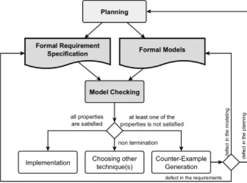
The current railway interlocking engineering practice is characterized by non-formal and semi-formal specifications and system designs (consisting of textual and ad hoc descriptions) written by the domain engineers. The communication between the stakeholders often causes misunderstanding and/or uncertainty. Using formal models during the development process - an example process is shown in Fig. 1 - can reduce these difficulties, as they support the rigorous specification, planning and verification of complex systems, and the identification of errors in the early life cycle phases. Formal models are typically executable, i.e. they can be tested early in their production. Using suitable analytical tools model checking can be applied, allowing full discovery and verification of the models’ behavior. When a qualified code generator generates the code from the model, this proof of correctness will remain valid for the code in the scope of the verified properties.
Verification and Validation (V&V) activities need to be applied systematically in the different phases of the life-cycle of safety-critical systems (this is also prescribed by the relevant standards). There are a lot of different existing approaches to life-cycle management, e.g. [6]. A possible life-cycle model (commonly known as the ‘V-model’) of the railway interlocking software development is shown in Fig. 2 (left side), [7]. The research presented here aims at preparing an automated process, which supports the domain engineers’ work during the requirement, design and implementation phase. As an added benefit, due to the use of an automated verification process some V&V life-
cycle activities can be skipped, result in a reduced ‘Y-life-cycle model’ that requires less time and human resources [8]. Schematic figure of this process is shown in Fig. 2.
Fig. 1. One part of development life cycle (the planning process) applying formal modeling
Fig. 2. The schematic way from V-model (left side) to Y-model (right side) (on the basis of [1], [7] and [8])
3. Related work
The application of formal methods in the railway interlocking system development has a long history. The trends in the use of formal methods to railway signaling are well summarized in [9]. There are many positive experiences with various formal methods in the railway interlocking system development, e.g:
‒ The use of B-method to specify behavior of a screen door controller [10]. The project developed a methodology, which is efficient and well-suited to systems requiring high-level of safety. The paper discusses several issues that have to be solved to achieve a more efficient process, e.g. the manual translation from B models to the target language (Ladder diagram) requires a specific verification process;
‒ The use of CSP||B to modeling a real double junction [11]. CSP||B combines event-based with state-based modeling, where CSP stands for Communicating Sequential Processes and B is the B-method. The goal of this paper is to create formal models, which are straightforward to understand and verify by industrial partners. According to the authors the representation of the different type (event-based or state-based) components are easy with using a solely event- based or a solely state-based framework, but the different encodings makes them difficult to understand, which is not appreciated by the railway engineers.
Formal Requirement Specification Formal Models
modelchecking
Report of Modelchecking Planning
User Requirement Specification
requirement analysis
architecture design conceptual
design
System Requirement Specification
Architecture Plan Conceptual
Design
High-Level System Design preliminary
design
allocation of requirements
Detailed (Formal) Plans detailed design
Functional & Safety Requirement Specification
requirement formalization automated transformation
V
System Development(external phase)
Software Requirements
Software Architect.
and Design
Software Component Design
Software Component Implementation
Software Component Testing Software Integration
Software Validation Software Maintenance
System Development (external phase)
Software Requirements
Software Component Design
Automated Code Generation
Automated Integration
Software Validation Software Maintenance
Formal Requirements
Integration Model
Component Formal Models
Model Checking Software Architect.
and Design
In the area of software development for industrial control systems a similar methodology is applied, discussed by [12]. The proposal of that work consists of two parts: a verification workflow, which is implemented using model checking, and a formal specification language to hide the mathematical/computer science background from the industrial practitioners. All these can be applied to development of PLC-based control software. The purposes of this research are to create a specification/verification workflow (without implementation) to give a domain-specific formal specification language, and to use model checking on safety-critical, embedded microcomputer-based railway interlocking systems. In the D.28 Chapter (Annex D) of the EN 50128 [13]
standard a short introduction of formal methods is given, which includes the statement:
‘Each application domain requires different modeling methods and different proof approaches.’ The research, discussed in this paper is also motivated by this observation.
4. Methodology
A traditional and planned development process is shown in Fig. 3. The process input is the domain specification (see Fig. 3 or Fig. 4), which consists of two parts: behavior and feature descriptions by using domain specification from the practical life.
In the first phases of the development process there is a decision about the necessity and/or advantage of using formal methods. This is a multifaceted decision, whose details are not intended to be covered in this article. (For example the EN 50128 Annex
‘A’ [1] gives a collection of the techniques appropriate for the chosen SIL and their expedient combinations. A certain recommended combination may require the use of formal methods. Whether choose this combination or not will depend on the developed system and its components, and even the verification plan, etc.) If formal methods are not used, then a traditional development process is followed. When the formal methods are chosen, then the planned specification-verification platform is used to generate formal models and to perform their verification with those tools, which are recommended for the platform. The overall goal is to generate inputs of automated code generation.
This research uses model checking (see Fig. 4) to verify the models. Model checking [14] is a method of computer science to answer the following question: does the model conform to a set of requirements, or if there is a requirement violation, then how can this situation occur? In case the requirements are fulfilled, then the model is considered to be verified correct. If there is a requirement violation, then model checking provides a counter example, which is an incorrect behavior of the model. The possible outputs of model checking [5] are summarized of the model checking process in Fig. 4. The term ‘non termination’ means that either the verification fails due to insufficient memory or the verification is shut down prematurely, because it takes too much time.
In this research the selected two formalisms to describe behavioral domain models are: Petri nets [15, pp. 459‒475] and finite automata [16]. These popular techniques have been applied for a long time on the railway interlocking development [17], [18], [19].
Fig. 3. The research goal and the process
Fig. 4. Model checking: An application
The selected tools for the research are the PetriDotNet (PDN) modeling and verification tool [20] and the UPPAAL framework (developed by UPPsala University and AALborg University) [21]. These tools are suitable for the modeling and simulation of railway interlocking systems, and fulfill many other factors that were taken into account during the selection process (e.g. the portability of the model, the generated output, the analysis ability, the simulation ability, the verification ability, etc.).
To formalize requirements the Computation Tree Logic (CTL) temporal language was chosen, [22] considering that it is an appropriate language to describe the requirements, and the above verification tools can handle this language.
5. Case study
The goals were to identify the transformation rules from the domain specification to the formal model and to set the constraints onto the domain specification (e.g. only Unified Modeling Language (UML [23]) and truth table can be used), because it is
BEHAVIOR FEATURE
Is the formal method
required?
DOMAIN SPECIFICATION (informal and \ or semiformal)
PREPARE FOR THE BEHAVIORAL DESCRIPTION
PREPARE FOR THE FEATURE DESCRIPTION PLATFORM FOR PREPARING AUTOMATED FORMALIZATION
TRADITIONAL DESIGN
TOOLSET FOR THE AUTOMATED FORMALIZATION
AND VERIFICATION
IMPLEMENTATION (ie. automated code generation)
YES NO
Model Checking
Implementation Choosing other technique(s)
Counter-Example Generation Formal Requirement
Specification Formal Models
defect in the requirements
defect in the modeling
Planning
defect in the planning
non termination all properties
are satisfied
at least one of the properties is not satisfied
necessary to automate the formalization and verification processes. A case study from practice is used to identify transformation rules and constrains. Currently manual methods are being used for the identification processes [24].
A detail from practical functional specification of the occupancy detection subsystem is described. This is a small software module: a detection point (see Fig. 5).
Fig. 5. Case study: A track detail with detection points
To sum up the logical behavior of the detection point: it is very simple, if the train is over the detection point it is ‘occupied’, and when the train is not over the detection point it is ‘clear’. The detection point may be faulty. This behavior is described with a truth table (see Table I).
Table I
The functional specification of the detection point (detail) Internal
state Inputs Outputs
New internal state Fault Fault P Fault N Occup. P Occup. N Fault Occup. Fault - not faulty not faulty clear clear not faulty clear not faulty not faulty not faulty not faulty clear occupied faulty occupied faulty not faulty not faulty not faulty occupied free faulty occupied faulty not faulty not faulty not faulty occupied occupied not faulty occupied not faulty
- faulty - - - faulty occupied faulty
- - faulty - - faulty occupied faulty
faulty - - occupied - faulty occupied faulty
faulty - - - occupied faulty occupied faulty
Notation: - do not care, P: not negated input, N: negated input, Occup.: Occupancy
Note, that the functional specification of the detection point contains a lot of other elements, for example the handling of timings, management of parameters, etc. These elements are not shown in this paper for simplicity (see Fig. 3 and Fig. 4).
From the initial functional specification (see Table I) a detailed specification is made. The goals of the detailed specification are to clarify specification mistakes, to make the specification more formal, and to clean up the plan. After that an intermediate model is developed. The intermediate model is transformed automatically to a given formalism, e.g. Petri net or automata. The transformation steps necessary for this case study are described in [24].
track
detection point 'A'
detection point 'B' section
6. Results
In this section the result of transformation from functional specification into formal models (Petri net and UPPAAL automata) is summarized and some examples of verification (model checking) are shown. Simple Petri nets are applied because of the portability of the model between different Petri net modeling tools.
6.1. The Petri net model of the detection point
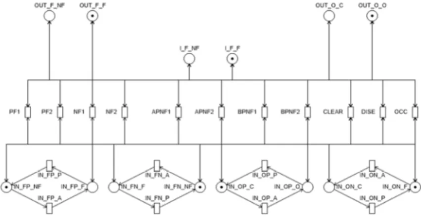
The Petri net model of the detection point is shown in Fig. 6. At the bottom of the Petri net are the inputs (transitions and places are marked with prefix (‘IN_’, from Input). The detection point has four inputs, two occupancy and two faulty. Two of them are positive logic inputs and have two information types (‘_FP_’, from Faulty Positive, and ‘_OP_’ from Occupancy Positive) and two of them are negative logic (‘_FN_’, from Faulty Negated, and ‘_ON_’, from Occupancy Negated). In the case of the places, the ‘_NF’ denotes ‘non-faulty’, ‘_F’ denotes ‘faulty’ and in the case of occupancy ‘_C’
denotes ‘clear’ and ‘_O’ denotes occupied (see Table I).
Fig. 6. The Petri net model of detection point
The detection point has an internal state, which is shown in the middle of Fig. 6 (I_F_NF and I_F_F places), where I_F_NF means that the detection point is not faulty, I_F_F that it is faulty. At the top of the Fig. 6 there are the output places of the model (‘OUT_’, from Output). Note, that the marking of the outputs is similar to the marking of the inputs. In the middle of the Fig. 6 one can see the transitions, which represent the behavior of the detection point. Those transitions whose names include ‘F’ mean the different ways of getting into the faulty state. The transition ‘OCC’ means that the detection point gets into an occupied state, the ‘CLEAR’ means that it gets into clear state and the ‘DISE’ transition symbolizes the disengage (reset) process.
Note that it is not the goal to produce a readable Petri net, because of the planned automated model generation. Note, that Fig. 6 does not provide full information about the Petri net, because several edges are routed along the same path, and thus they
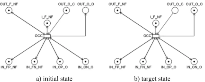
became indistinguishable. In Fig. 7 there is a simple part of the detection point model, where the behavior of one transition (OCC) can be traced fully.
a) initial state b) target state Fig. 7. Part of the Petri net model describing the detection point
(detection point gets into the occupied state) 6.2. The UPPAAL model of the detection point
The UPPAAL model of the detection point is presented in Fig. 8. On the left side of the figure the automata of the inputs of the detection point are shown, and in the upper right corner the initialization expressions of the UPPAAL model can be seen in black color. The main automaton is in the middle of Fig. 8. (The marking scheme is the same as for the Petri net model).
Fig. 8. The UPPAAL model of detection point
6.3. Verification with model checking
In this paragraph some experiences about the model checking are given. Before that a brief overview is presented about the requirement formalization experiences (more detailed information is in [25]). There are three main types of requirements:
1. Requirements that can be formalized (mainly functional or safety requirements);
2. Requirements that cannot be formalized (e.g. non-functional requirements);
3. Requirements whose formalization depends on the level of the model (e.g.
definitions).
The following requirement is from the software requirements specification:
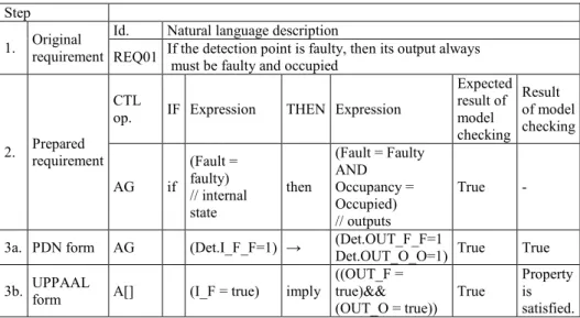
Example 1, REQ01 - If the detection point is faulty then its output always must be faulty and occupied.
The steps of the formalization process with explanations are shown in Table II.
Table II
Example of model checking - I Step
1. Original requirement
Id. Natural language description
REQ01 If the detection point is faulty, then its output always must be faulty and occupied
2. Prepared requirement
CTL
op. IF Expression THEN Expression
Expected result of model checking
Result of model checking
AG if
(Fault = faulty) // internal state
then
(Fault = Faulty AND
Occupancy = Occupied) // outputs
True -
3a. PDN form AG (Det.I_F_F=1) → (Det.OUT_F_F=1
Det.OUT_O_O=1) True True 3b. UPPAAL
form A[] (I_F = true) imply
((OUT_F = true)&&
(OUT_O = true)) True
Property is satisfied.
The next requirement is from the list of requirements issued by the operator [26].
This requirement cannot be formalized, because it is a non-functional requirement.
Example 2, REQ02-The components must also have a type ID and a unique identifier
The third requirement is a very high level, brief definition of the detection point.
This definition (requirement) is from System Requirements Specification (SRS) written by the developer.
Example 3, REQ03-The detection point is a device that detects the presence of the train
This definition is incomplete and inaccurate at the modeling level. To use this requirement for model verification, this sentence has to be clarified. This task that can be solved in many ways, but only domain engineers can make the choice between the alternatives, because they have the necessary expertise. Nevertheless, this requirement is well understood and verifiable in a high-level model of the system. One possible CTL form of the requirement is for example:
AG (Det.IN_O = 1) → (Det.OUT_O = 1). (1) Explanation of the above expression in natural language: ‘A’ is a CTL path quantifier meaning ‘on All paths’, and ‘G’ is a CTL temporal operator, meaning
‘Globally in every state’. After the temporal operators the Boolean expressions says: if the input of the detection point is occupied (‘Det.IN_O = 1’), then the output of the detection point shall be occupied (‘Det.OUT_O = 1’).
Note that the UPPAAL form of the requirement is very similar to the PDN form, just some notation is different:
(A[] (IN_O = true) imply (OUT_O = true)). (2)
This requirement does not say anything about the type of the occupancy inputs (at this phase of system development it is still not known whether the occupancy information is received in positive or negative logic, or any other form). It does not say anything about the configurability of the occupancy information, and it is not known how the other inputs affect the occupancy output, etc. To summarize the above, this requirement may be suitable for verification on the system level, but not for checking the formal model based on the detailed specification. It is necessary to properly translate (equivalently re-formulate it using the terms of the detailed formal model) this system level requirement.
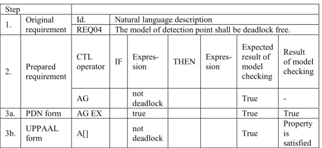
The last requirement comes from the formal verification expert. The steps of its formalization are shown in Table III.
Table III
Example of model checking - II Step
1. Original requirement
Id. Natural language description
REQ04 The model of detection point shall be deadlock free.
2. Prepared requirement
CTL
operator IF Expres-
sion THEN Expres- sion
Expected result of model checking
Result of model checking
AG not
deadlock True -
3a. PDN form AG EX true True True
3b. UPPAAL
form A[] not
deadlock True
Property is satisfied Example 4, REQ04-The model of detection point shall be deadlock free
The PDN application automatically determines the deadlock freedom, but the deadlock freedom can be checked with the help of the PDN model checker too with expression AG(EX(true)).
7. Conclusion
The primary goal of this research is to create a framework, in which the formal models can be automatically generated from the domain-oriented specification. In this process, the first step is to identify the transformation rules, but beside that it is also important to collect the exceptions and to constrain the specification language.
Verification can be done by formalizing the requirements. The aim is to create a specification-verification platform for domain engineers that hide the mathematical background of formal methods.
At the current point of the ongoing research only manual techniques are used to identify transformation rules from specification into formal models. The collection of rules is tested on single modules. For the case study presented in the paper, formal models were manually constructed from the informal or semi-formal specification. The transformation rules were not yet presented (due to size constraints), only concrete cases of formalization.
In the next step, the main challenges will be the implementation of the automated model generation and verification on the module level, and the development of algorithms for the (automatic) integration of these module-level models into system- level models. The far away goals of the work are the fully automated system-level verification process and the visualization of detected errors and defects for the domain engineers in a comprehensible form.
Open Access statement
This is an open-access article distributed under the terms of the Creative Commons Attribution 4.0 International License (https://creativecommons.org/licenses/by/4.0/), which permits unrestricted use, distribution, and reproduction in any medium, provided the original author and source are credited, a link to the CC License is provided, and changes - if any - are indicated. (SID_1)
References
[1] EN-50128, Railway applications-communication, signaling and processing systems- software for railway control and protection systems, 2011.
[2] BS EN-50129-2003, Railway applications: communications, signaling and processing systems-safety related electronic systems for signaling, 2003.
[3] Cai H., Zhang C., Wu W., Ho T. K., Zhang Z. Modeling high integrity transport systems by formal methods, Procedia - Social and Behavioral Sciences, Vol. 138, 2014, pp. 729‒737.
[4] Ricci S. The use of Petri Nets models in railway traffic applications, Internal Federation of Automatic Control Proceedings Volumes, Vol. 42, No. 5, 2009, pp. 151‒156.
[5] Ésik Z., Gombás É., Németh L. Z. Verification of hardware and software systems, (in Hungarian), TYPOTEX, 2011.
[6] Kovács G. L., Petunin A. An information view of manufacturing automation product life- cycle management, Pollack Periodica, Vol. 11, 2016, Issue 2, pp. 3‒14.
[7] CENELEC-EN-50126, Railway applications-the specification and demonstration of reliability, availability, maintainability and safety (RAMS), 1999.
[8] Camus J. L. Efficient development of avionics software with DO-178B safety objectives, Esterel Technologies, 2002, pp. 1‒31.
[9] Fantechi A., Fokkink W., Morzenti A. Some trends in formal methods application to railway signaling, in: Formal methods for industrial critical systems: A survey of applications, Gnesi S., Margaria T. (Eds.) Ch. 4, 2012, pp. 61-84.
[10] Leeomote T., Servat T., Pouzancre G. Formal methods in safety-critical railway systems, 10th Brasilian Symposium on Formal Methods, Ouro Preto, Brasil, 31 August 2007, pages 9.
[11] Moller F. Nguyen H. N., Roggenbach M., Schneider S., Treharne H. Railway modeling in CSP||B: the double junction case study, 12th Internal Workshop on Automated Verification of Critical Systems, Electronic Communication of EASST, Vol. 53, 2012, pp. 1-15.
[12] Darvas D. Practice-oriented formal methods to support the software development of industrial control systems, PhD Thesis, Budapest University of Technology and Economics, 2016.
[13] BS EN-50128, Railway applications. Communication, signaling and processing systems.
Software for railway control and protection systems, 2011.
[14] Kamide K., Yano Y. Logics and translations for hierarchical model checking, Procedia Computer Science, Vol. 112, 2017, pp. 31‒40.
[15] He X., MurataT. High-level Petri nets extensions, analysis, and applications, In: The Electrical Engineering Handbook, Chen W. K. (Ed.) Academic Press, Burlington, Ch. 9, 2005, pp. 459‒475.
[16] Keroglou C., Hadjicostis C. N. Verification of detectability in probabilistic finite automata, Automatica, Vol. 86, 2017, pp. 192‒198.
[17] Durmu M. S., Yildirim U., Eris O., Söylemez M. T. Safety-critical interlocking software development process for fixed-block signalization systems, Internal Federation of Automatic Control Proceedings Volumes, Vol. 45, No. 24, 2012, pp. 165‒170.
[18] Gjaldbæk T., Haxthausen A. E. Modeling and verification of interlocking systems for railway lines, Internal Federation of Automatic Control Proceedings Volumes, Vol. 36, No.
14, 2003, pp. 233‒238.
[19] Khan S. A., Zafar N. A., Ahmad F., Islam S. Extending petri net to reduce control strategies of railway interlocking system, Applied Mathematical Modeling, Vol. 38, No. 2, 2014, pp. 413‒424.
[20] Vörös A., Darvas D., Hajdu Á., Klenik A., Marussy K., Molnár V., Bartha T., Majzik I.
Industrial applications of the PetriDotNet modeling and analysis tool, Science of Computer Programming, Vol. 157, 2017, pp. 7‒40.
[21] Soliman D., Thramboulidis K., Frey G. Transformation of function block diagrams to uppaal timed automata for the verification of safety applications, Annual Reviews in Control, Vol. 36, No. 2, 2012, pp. 338‒345.
[22] Patthak A. C., Bhattacharya I., Dasgupta A., Dasgupta P., Chakrabarti P. P. Quantified computation tree logic, Information Processing Letters, Vol. 82, No. 3, 2002, pp. 123‒129.
[23] Object management group, unified modeling language V2.5, Object Management Group, 2015.
[24] Bartha T., Lukacs G. Opportunities of automated transformation of formal specification into a formal model in the interlocking systems area, In: Innovation and Sustainable Surface Transport, T. Peter (Ed.) Vol. XI, 2017, pp. 187‒196.
[25] Farkas B., Lukacs G., Bartha T. Experiences with requirement formalization in the railway interlocking development, In: Innovation and Sustainable Surface Transport, T. Peter (Ed.) Vol. XI, 2017, pp. 197‒204.
[26] Kiss L., Héri J., Takács P., Sághi B., Szabó G. Requirements for safety components and equipment of traffic control for the road railway (tram) systems, (in Hungarian) (BKV- VILL-1.04), BKV Zrt, 2011.