DOI: 10.1556/606.2019.14.1.6 Vol. 14, No. 1, pp. 59–66 (2019) www.akademiai.com
SWEPT VOLUME EVALUATION USING THE BSP-DEXEL REPRESENTATION FOR THE 5-AXIS
CNC MACHINING SIMULATION
1 Dmitry V. KURENNOV, 2 Evgenii I. KATZ, 3 George L. KOVÁCS*
1,2 Ural Federal University, Mira str, 19, Ekaterinburg, 620002, Russian Federation e-mail: 1d.v.kurennov@urfu.ru, 2ekatz2@gmail.com
3 Computer and Automation Research Institute, Hungarian Academy of Sciences H-1111 Budapest, Kende u. 13-17, Hungary, e-mail: kovacs.gyorgy@sztaki.hu
Received 21 May 2018; accepted 30 October 2018
Abstract: A new approach to the construction of a volume swept by the cutting tool is proposed for modeling 5-axis computer numerical control milling. A tool is considered to take the form of an arbitrary body of revolution. The main difference of the proposed approach is to provide the possibility of direct construction of the bulk synchronous parallel-dexel model, which, in turn, provides an effective modeling of the cutting process. Thus, it was possible to expand the scope of the given model by including the possibility to simulate arbitrary 5-axis computer numerical control programs. To confirm the correctness of the proposed approach, a program implementation of the corresponding algorithms has been performed. Examples of modeling of 5- axis milling processing of real parts and data on time costs for the suggested modeling are given.
The high efficiency of the proposed approach is proven by the results of the experiments.
Keywords: 5-axis machining, Computer numerical control, Tool swept volume, Bulk synchronous-dexel model, Bulk synchronous parallel tree
1. Introduction
Simulation of the machining process of a part on a metalworking (milling, turning, etc.) machine with Computer Numerical Control (CNC) is an integral part of automation of production preparation process [1], [2]. The solution to this problem is often used at the stage of CNC program development and is always necessary at the stage of this program verification. See [3] for completely different character of design task. Recently a new approach to the solution of this problem was suggested in [4],
* Corresponding Author
differing, first of all, by the higher quality of the final result. This approach is based on the idea of the Bulk Synchronous Parallel-dexel (BSP-dexel). BSP is abbreviation of Binary Space Partitioning model. The basic idea is to save information on certain small area around a dexel inside it, which allows to exactly represent this area analytically, to put it more precisely, the surface area inside a rectangular parallelepiped confined within this dexel and three adjacent dexels. This parallelepiped is named a cell. It is proposed to save a BSP model uniquely and exactly representing polyhedral surface inside the cell. In [4], the authors confined themselves to study 3 + 2 machining only.
This term also known as 5-axis positional machining means that work passes of tools are carried out in three coordinates, while two rotational coordinates are used only for tool positioning and not used during cutting.
In this paper an extension of this approach for a full-scale modeling of 5-axis machining is proposed. To achieve this goal, it is necessary to develop an algorithm for constructing the BSP-dexel model of the tool swept volume of 5-axis machining.
Dexel (‘depth pixel’) is a concept used for a discretized representation of functions defined on surfaces used in geometrical modeling and physical simulation for manufacturing, when work-piece surfaces are subject to modifications. Dexel is a nodal value of a scalar or vector field on a meshed surface.
It has to be mentioned that tool and toolpath generation are important issues in very different technologies and applications, as for example even the incremental sheet forming [5] gives challenging tasks in 2-2.5D.
2. Related works
Following [6] two major approaches to computing cutter swept volume can be distinguished. One is computing the sweeping envelopes [7] and integrating them to form the surface of the swept volume [8]-[10], where [5] deals with milling processes, [6] with simulation, and [8] with complete swept volume generation. The other method is to use a global spatial structure (or spatial directory) to describe the shape [9]-[11], more precisely [8] takes care of Numerical Control (NC) milling, [10] simulates and [12] gives details on intersections.
One of the most important problems in the construction of a swept volume, which significantly affects the efficiency of solving the entire problem, is the elimination of self-intersections of the surface. Campen M., Kobbelt L. [13], [14] proposed an approach based on the use of BSP trees. The basic idea is to build a tree containing all the elements of the surface, and then remove the surface areas that lie inside the swept volume. The result is a BSP tree that describes a polytope that approximates the volume to be swept out. In [13], a closed polygonal mesh containing only local self- intersections is considered, and in [14] both these restrictions are removed and a universal approach is proposed.
To increase efficiency an additional octal tree is used by the authors and individual BSP trees are built for each surface fragment contained in the cell of the octal tree. The idea of using this additional tree is close to the idea of the BSP-dexel model. In both cases, a lot of trees are used, each of which describes a small part of the modeled object, bounded by a region of simple form. In [14], the criterion for stopping cell division is
the number of polygons in this cell. This value has been determined experimentally and is approximately 60.
In the recent case, the shape and dimensions of the BSP-dexel cell are established at the stage of construction of the initial model and cannot be changed during the work.
The second difference is that the BSP tree in [13], [14] is used as an intermediate data structure. The ultimate goal is to construct a boundary representation of the simulated volume. For this case the constructed BSP tree is the final result, and it is used to perform Boolean operations.
3. Building a swept volume
The general scheme of the selected approach to solve the problem is described.
First step:
The tool trajectory is approximated by segments of the screw line [15]. More precisely, it is not a trajectory, what is approximated, but a function that determines the motion of a rigid body in space by a sequence of screw motions. The use of screw motions makes it possible to considerably simplify the building of the swept volume boundary in the following stages due to the fact that the grazing curve remains unchanged in the tool coordinate system [16].
Second step:
For each element of the screw motions sequence, a grazing curve is constructed. To solve this problem a method similar to that proposed in [17] is used. Author suggests analytically proven closed-form solution for computing the grazing points generated by a surface of revolution. The details are not fundamental for our algorithm.
After this, it is necessary to construct triangular grids corresponding to the parts of the tool surface located on different sides of the grazing curve.
The swept volume boundary can now be obtained by combining these grids located at the beginning and at the end of the path segment with the surface obtained by moving the grazing curve in accordance with one element of the screw motion. At the same time, coordinated directions of faces of normal vectors are provided, i.e. external normal vectors are computed for each face of the triangular grid.
Third step:
The closed oriented triangular grid obtained in the second stage is converted into the BSP-dexel model.
Let us now consider the third stage in more detail. There is a continuous closed oriented triangular mesh, possibly containing self-intersections. It is necessary to construct a BSP-dexel model that accurately describes the surface of the swept volume and is free from self-intersections.
First of all, it is necessary to build BSP trees for each BSP-dexel. More precisely, for each rectangular parallelepiped whose faces are parallel to the coordinate planes, it is
necessary to construct a BSP tree corresponding to those triangles of the original mesh, which intersect with this parallelepiped.
For this purpose, a well-known algorithm [18] is used. The essence of the algorithm is the sequential recursive insertion of the faces of the original mesh into the initially empty BSP tree. The approach proposed in [19] makes it possible to effectively divide the original triangles into parts corresponding to different BSP-dexels. During the construction process, we will keep the contours of the corresponding faces in the nonterminal nodes, and label the terminal nodes as internal or external in accordance with the direction of the faces external normal vectors. These normal vectors were determined in the second step. As a result, a set of BSP trees will be generated. Since the original surface can have self-intersections, the marking of terminal nodes (internal or external) may be erroneous.
Note that these errors can only be of one kind. All nodes marked as internal are marked correctly. Only the ‘external’ label can be wrong. In addition, in the process of construction, the fact of the presence or absence of self-intersections is fixed. If there were no self-intersections, then the constructed tree would be correct and the next step was just not needed.
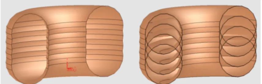
The next step is to markup terminal nodes. Fig. 1 shows examples of self- intersections. In [13], it is proposed to construct the BSP-cell adjacency graph for these purposes. The vertices in this graph correspond to the terminal nodes of the BSP tree.
Two vertices are joined by an edge if the corresponding BSP cells are adjacent. In the given case, a simpler and more efficient procedure can be applied.
Fig. 1. Illustration of self-intersections in polygonal meshes, Right image shows original mesh.
Left image shows the mesh after self-intersections removal
A. Place all BSP tree leafs marked as outer, in a set of unused leafs;
B. While the set of unused leafs is not empty;
1. Extract the leaf from the set;
2. Create a straight line parallel to the dexel direction, through any point of the BSP-cell corresponding to the leaf;
3. Moving along the straight line, mark out all leafs whose BSP-cells intersect this line, and remove them from the set of unused leafs.
Step B.3 is performed as follows. Initially, a zero value is assigned to the intersection counter. By traversing leafs along a line, to each passed leaf the status
‘external’ is assigned if the counter is zero and ‘internal’, otherwise.
For each intersection of the straight line with the face of the original surface stored in the BSP-tree increase the value of the counter by 1 if the direction of the outer normal vector to the face coincides with the direction of motion along the line, and decrease it by 1, otherwise.
The idea is concretized in the form of the recursive algorithm Mark (v, p0, p1). Here v is the root of the tree to be marked, p0 and p1 are points on a straight line parallel to the dexel direction, located on opposite sides of this dexel. v.plane is the plane corresponding to the vertex v. v.plane.normal is the outer normal vector to v.plane.
v.face is the face corresponding to the vertex v.
Mark (v, p0, p1):
A. If v is a leaf:
1. Mark v as ‘external’ if the counter is zero and ‘internal’ otherwise.
2. Remove v from the set of unused leafs.
3. Return.
B. If the line segment p0,p1 does not intersect the plane v.plane:
1. Find s - the descendant of v containing the segment.
2. Mark (s, p0, p1).
3. Return.
C. Find p, the intersection point of the line segment p0,p1 and v.plane.
D. Find the s0 and s1 - descendants of the vertex v containing p0 and p1, respectively.
E. Mark (s0, p0, p).
F. If p lies inside v.face:
1. If the (p1 - p0) * v.plane.normal > 0:
A. Increase the counter by one.
2. Otherwise
A. Decrease the counter by one.
G. Mark (s1, p, p1).
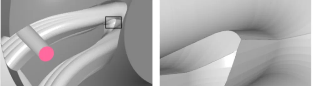
To illustrate the results of the proposed approach, Fig. 2 shows an example of the result of simulation of 5-axis machining. The initial stage of impeller machining is shown. To assess the quality of the model obtained, Fig. 3 shows an enlarged image of the fragment selected by the frame in Fig. 2.
Fig. 2. An impeller processing stage Fig. 3. An enlarged image of a fragment
4. Experimental research
To evaluate the performance of the proposed algorithms and the quality of the obtained modelling results, a software implementation and computational experiments were performed. A computer with Intel Core i7-2700K 3.50GHz CPU, 8 GB RAM, OS Windows 7 x64 was used for the experiments. Programs were compiled with Visual Studio 15 C++. 64-bit binaries were used.
A characteristic feature of the BSP-dexel model is the lack of dependence of the quality of the result obtained on the amount of dexels in the model. At the same time, the amount of dexels affects significantly the model construction time, and this dependence is not monotonous. Proceeding from this point, the experiment scheme is constructed as follows.
The first step was to determine the optimal value of the number of BSP-dexels, which provides the maximum speed. After that, the resolution was chosen for the traditional three-dexel model, which would give the same speed. As a result, pairs of models were obtained for the same objects. The time costs for obtaining them by the two compared methods are the same. These pairs were compared in terms of the quality of the result obtained.
Comparison was made on the base of algorithm of surface recovery from tri-dexel model, containing surface normal vectors in each dexel vertex [20], as it provides higher quality results. Using programs for surface recovery, which do not consider normal vectors, results in a more significant difference.
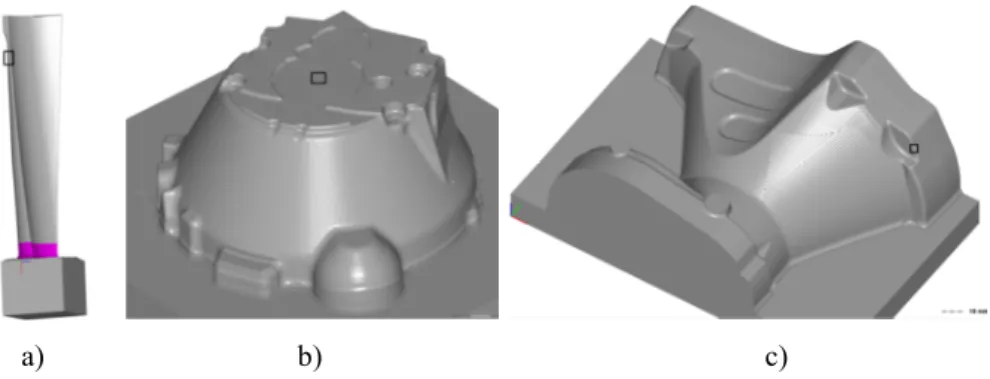
Three parts (Fig. 4) obtained by the 5-axis machining were selected to study.
Programs for processing these parts contain 24, 55 and 100 thousand lines respectively.
The results of the experiments are summarized in Table I.
a) b) c)
Fig. 4. a) Part model 1, b) Part model 2, c) Part model 3
Fig. 5 show magnified fragments of parts, highlighted by small frames on Fig. 3, (upper left, upper middle, right middle). On the left-hand side there are the fragments of the tri-dexel model, on the right-hand side there are the fragments of the BSP-dexel models. It is clear, that right hand side fragments much better depict small elements.
Table I
Experimental results Part Program size
(thousands of lines)
BSP-dexels qty.
(pcs.)
Processing time (sec)
dexels qty.
(thou.)
Comparison
1 24 8000 14 3200 Fig. 4a.
2 55 4000 9 2400 Fig. 4b.
3 100 8000 23 2800 Fig. 4c.
a)
b) c)
Fig. 5. Fragment of part model a) 1; b) 2; c) 3
5. Conclusion and further work
A method allows significantly expanding the scope of the BSP-dexel model is proposed. This method ensures the geometric modeling of arbitrary 5-axis machining using all advantages of the BSP-dexel model. The productivity and quality of the proposed approach are confirmed by experimental studies.
The next stage of the work should be the dissemination of the results obtained to other technological processes, primarily the modeling of additive technologies.
References
[1] Jacobs B. The expanding role of simulation, Tooling and Production, Vol. 71, No. 7, 2005, pp. 28–31.
[2] Kovács G. L., Petunin N. An information technology view of manufacturing automation - product life-cycle management, Pollack Periodica, Vol. 11, No. 2, 2016, pp. 3‒14.
[3] Berezin I. M., Petunin A. A., Kryuchkov D. I., Kovács G. L. Finite-element simulation of the cold stamping process of spherical vessels Pollack Periodica, Vol. 12, No. 1, 2017, pp. 81‒92.
[4] Kats E. I., Kitaev A. M. On the approach to CNC machining simulation improving, Proc.
International Conference on Industrial Engineering, Applications and Manufacturing (ICIEAM-2017), Saint Petersburg, Russia, 16-19 May 2017, pp. 1−4.
[5] Paniti I. CAD API based tool path control for novel incremental sheet forming, Pollack Periodica, Vol. 5, No. 2, 2010, pp. 81‒90.
[6] Li Y., Lee C. H., Gao J. From computer-aided to intelligent machining: Recent advances in computer numerical control machining research, Proc. IMechE, Part B, J. Engineering Manufacture, Vol. 229, No. 7, 2015, pp. 1087−1103.
[7] Blackmore D., Leua M. C., Wang L. P. The sweep-envelope differential equation algorithm and its application to NC machining verification, Computer-Aided Design, Vol. 29, No. 9, 1997, pp. 629−637.
[8] Plakhotnik D., Lauwers B. Computing of the actual shape of removed material for five-axis flat-end milling, Computer-Aided Design, Vol. 44, No. 11, 2012, pp. 1103−1114.
[9] Wu W., Li J., Feng Q. Simulation of the surface profile of the groove bottom enveloped by milling cutters in single screw compressors, Computer-Aided Design, Vol. 43, No. 1, 2011, pp. 67−71.
[10] Lee S. W., Nestler A. Complete swept volume generation, Part I, Swept volume of a piecewise C1-continuous cutter at five-axis milling via Gauss map, Computer-Aided Design, Vol. 43, No. 4, 2011, pp. 427−441.
[11] Sullivan A., Erdim H., Perry R. N., Frisken S. F. High accuracy NC milling simulation using composite adaptively sampled distance fields, Computer-Aided Design, Vol. 44, No. 6, 2012, pp. 522−536.
[12] Miao Y., Song X., Jin T., Shan Y. Improving the efficiency of solid-based NC simulation by using spatial decomposition methods, Int. J. Adv. Manuf. Technol. Vol. 87, No. 1-4, 2016, pp. 421–435.
[13] Campen M., Kobbelt L. Exact and robust (self-)intersections for polygonal meshes, Comput. Graph. Forum, Vol. 29, No. 2, 2010, pp. 397–406.
[14] Campen M., Kobbelt L. Polygonal boundary evaluation of Minkowski sums and swept volumes, Comput Graph Forum, Vol. 29, No. 5, 2010, pp. 1613–1622.
[15] Cripps R. J., Mullineux G. Using geometric algebra to represent and interpolate tool poses, International Journal of Computer Integrated Manufacturing, Vol. 29, No. 4, 2016, pp. 406−423.
[16] Rossignac J., Kim J. J., Song S. C., Suh K. C., Joung C. B. Boundary of the volume swept by a free-form solid in screw motion, Computer-Aided Design, Vol. 39, No. 9, 2007, pp. 745–55.
[17] Aras E. Generating cutter swept envelopes in five-axis milling by two-parameter families of spheres, Computer-Aided Design, Vol. 41, No. 2, 2009, pp. 95−105.
[18] Thibault W. C., Naylor B. F. Set operations on polyhedra using binary space partitioning trees, Proceedings of the 14th Annual Conference on Computer Graphics and Interactive Techniques, NY, USA, Vol. 21, No. 4, 1987, pp. 153–162.
[19] Bernstein G., Fussell D. Fast, exact, linear Booleans, Proceedings of the Symposium on Geometry Processing, Berlin, Germany, 15-17 July 2009, Vol. 28, No. 5, 2009, pp. 1269–1278.
[20] Ren Y., Zhu W., Lee Y. H. Feature conservation conversion of tri-dexel, volume models to polyhedral surface models for product prototyping, Computer-Aided Design and Application, Vol. 5, No. 6, 2008, pp. 932−941.